Development of Small-Footprint Thermal Sensor Detecting Airflow at Mouth in Baby †
by
 and
and
Yuki Mitsunari
1,*, 
Yoshihiro Hasegawa
1,
Miyoko Matsushima
2,
Tsutomu Kawabe
2 and
Mitsuhiro Shikida
1 1
Hiroshima City University, 3-4-1, Ozuka-Higashi, Asa-Minami-Ku, Hiroshima 731-3194, Japan
2
Nagoya University, 1-1-20, Daiko-Minami, Higashi-ku, Nagoya 461-8673, Japan
*
Author to whom correspondence should be addressed.
†
Presented at the Eurosensors 2017 Conference, Paris, France, 3–6 September 2017.
Proceedings 2017, 1(4), 359; https://doi.org/10.3390/proceedings1040359
Published: 7 August 2017
(This article belongs to the Proceedings of Proceedings of Eurosensors 2017, Paris, France, 3–6 September 2017)
Abstract
:This paper presents a novel tube flow sensor to measure airflow in mouths for detecting respiration and heartbeat signals of premature babies in incubators. A flow rate sensor with temperature compensation and a flow direction sensor were combined to decrease their footprint on a sensor film. The fabricated sensor film was assembled onto the inside surface of the tube, and its detection properties were investigated. The sensor output in the flow rate sensor obeyed King’s model. The value of output in the flow-direction sensor was changed in accordance with the change of the airflow direction.
1. Introduction
Respiration and heartbeat values are the most important vital signals. Generally, each signal is detected by respective medical equipment, such as a spirometer and an electrocardiogram (ECG). On the one hand, the airflow at the mouth contains both respiration and heartbeat signals because the lungs are connected to the heart. This means that both respiration and heartbeat signals can be detected by a single airflow measurement at the mouth. Thus, a tube flow sensor was previously developed to detect the airflow waveform at the mouth (Figure 1) and was experimentally proved to be able to detect both respiration and heartbeat signals by analyzing the waveform [1].
However, for infants, whose skin is usually very sensitive, medical equipment should be in contact with the skin for as short a time as possible. Thus, tube flow sensor technology was used to measure respiration and heartbeat of premature babies in incubators in this study because it does not need electrodes to be attached like in ECG measurement (Figure 2).
From a technical viewpoint, the previous sensor occupies a relatively large footprint of the sensor patterns, and the two flow sensors have the same property because they measure oscillating airflow. Thus, we introduced new sensor patterns to reduce the sensor footprint and experimentally studied the sensor properties: flow rate, flow direction, and temperature compensation.
2. Tube Flow Sensor
2.1. Sensor Design
In the previous sensor design, the sensor consisted of two sets of heater and temperature compensation sensors to detect both flow rate and flow direction for the different oscillating airflows (breathing) of different temperatures (Figure 3a). However, the sensing pattern had a large footprint. To overcome this problem, a single heater with temperature compensation sensor and a flow-direction sensor were combined, which decreased the footprint on the sensor film (Figure 3b) to 64% of that in the previous tube flow sensor.
In the designed sensor, the heater works as the flow-rate sensor and the temperature compensation sensor compensates for the temperature change of the airflow. Two temperature sensors located upstream and downstream of the heater were used as the flow-direction sensors, and flow direction is judged by subtracting the value of one temperature sensor from that of the other. The two-layered tube structure was used to produce a cavity under the sensing area for the thermal isolation. An outer tube 3.5 mm in diameter was designed to apply the tube flow sensor to premature babies in incubators.
2.2. Sensor Fabrication
3. Experiments and Results
3.1. Flow Rate Measurement
The sensor output vs. flow rate was evaluated by using a commercially available mass flow controller. The sensor outputs in both flow directions were coincident even if airflow direction changed, as shown in Figure 5 (which means the sensor output can be described by the single calibration curve). The sensor output also obeyed King’s model, and thus we plotted the calibration curve as shown by the solid-line in Figure 5. The calibration curve was used in the flow rate measurement in actual use. An evaluation found that the flow-direction sensor operation did not affect the flow rate measurement (Figure 6).
The airflow temperatures in the inspiration and expiration are basically different, so the effect of the airflow temperature change ranging from 22 to 36 °C on the flow-rate measurement was evaluated. Thanks to adding the temperature compensation function, the sensor output in the flow-rate measurement did not depend on the airflow temperature even if the thermal convection was applied as the operation principle in the flow rate measurement (Figure 7).
3.2. Flow Direction Measurement
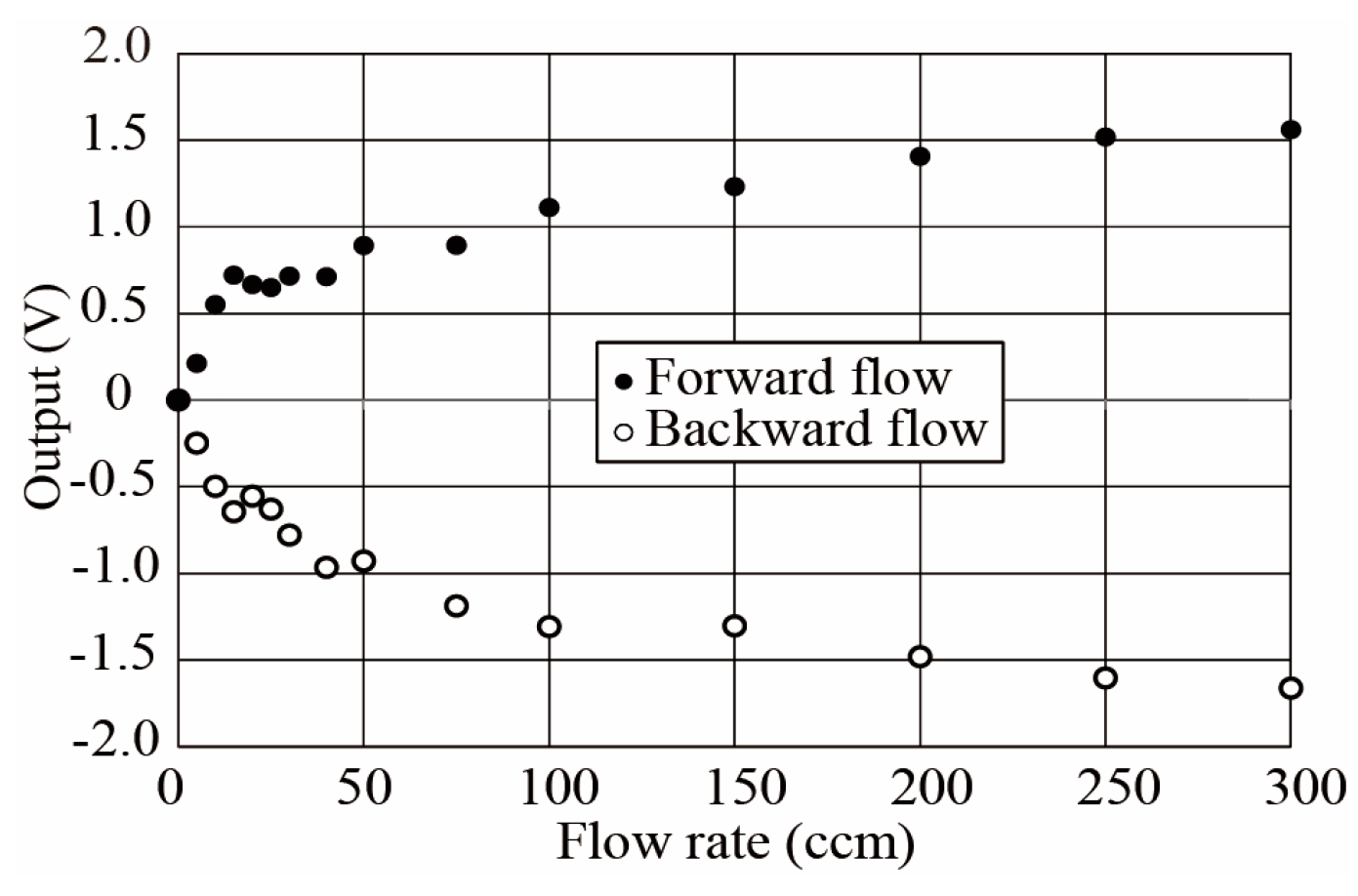
Flow direction was determined by subtracting the value of one temperature sensor output from that of the other. The obtained subtraction value is plotted in Figure 8. The plus and minus values changed in accordance with the change of the airflow direction.
4. Conclusions
Tube flow sensor technology has been developed to measure the respiration and heartbeat of a premature baby in an incubator. A single heater with a temperature compensation sensor and a flow-direction sensor were combined, which decreased the footprint area on the sensor film to 64% of that in the previous tube flow sensor. The sensor functions were tested in experiments, and the obtained results showed accurate respiration measurement. We are now planning to apply the developed sensor to measure airflow at mouths of small animals.
Acknowledgments
This research was supported by JSPS KAKENHI Grant Number 26286034, Japan.
Conflicts of Interest
The authors declare no conflict of interest.
References
- Kawaoka, H.; Yamada, T.; Matsushima, M.; Kawabe, T.; Hasegawa, Y.; Shikida, M. Detection of kinetic heartbeat signals from airflow at mouth by catheter flow sensor with temperature compensation. In Proceedings of the Technical Digit of IEEE MEMS Conference, Shanghai, China, 24 January 2016; pp. 359–362. [Google Scholar]
- Watanabe, S. Response time shortening in thermal catheter flow sensor. In Proceedings of the Technical Digit of Asia-Pacific Conference of Transducers and Micro-Nano Technology 2016, Kanazawa, Japan, 26–29 June 2016; pp. 253–254. [Google Scholar]
Figure 1.
Airflow signal containing both respiration and heartbeat information.
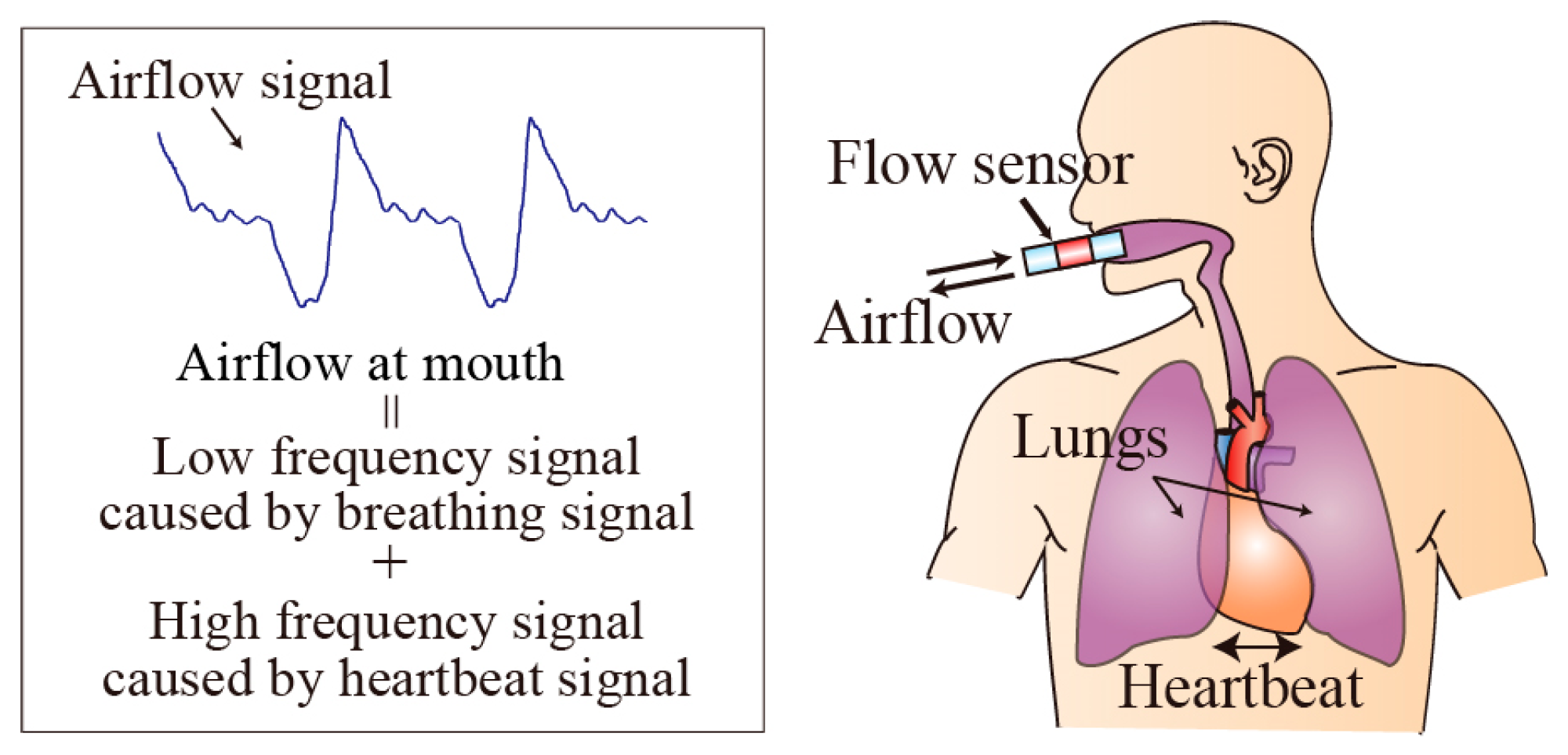
Figure 2.
Breathing control and heartbeat detection in premature baby in incubator.
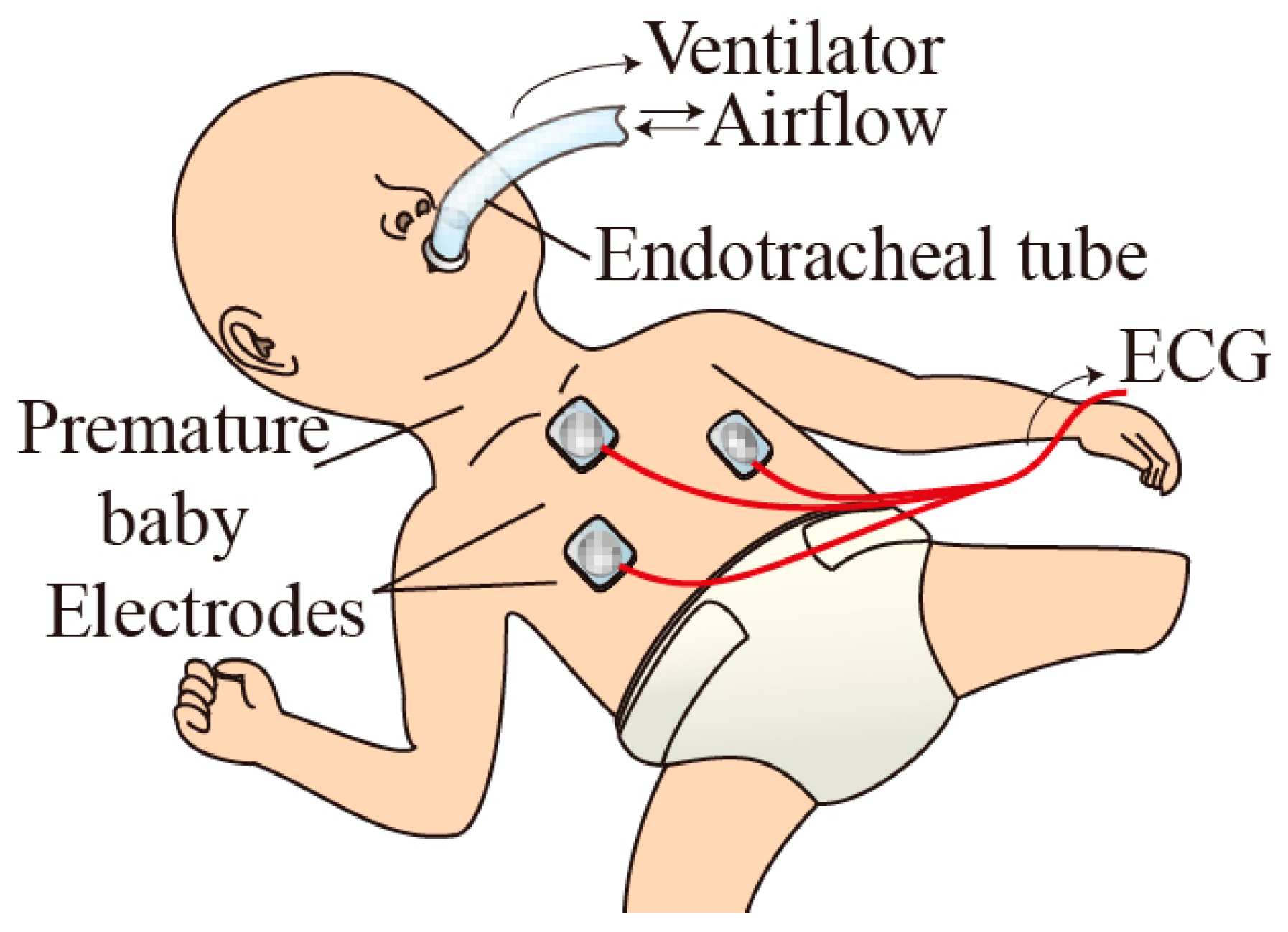
Figure 3.
Tube flow sensor for detecting both flow rate and flow directions: (a) Previous sensor; (a-1) design of sensor elements; (a-2) schematic view; (b) Proposed sensor; (b-1) design of sensor elements; (b-2) schematic view.
Figure 3.
Tube flow sensor for detecting both flow rate and flow directions: (a) Previous sensor; (a-1) design of sensor elements; (a-2) schematic view; (b) Proposed sensor; (b-1) design of sensor elements; (b-2) schematic view.
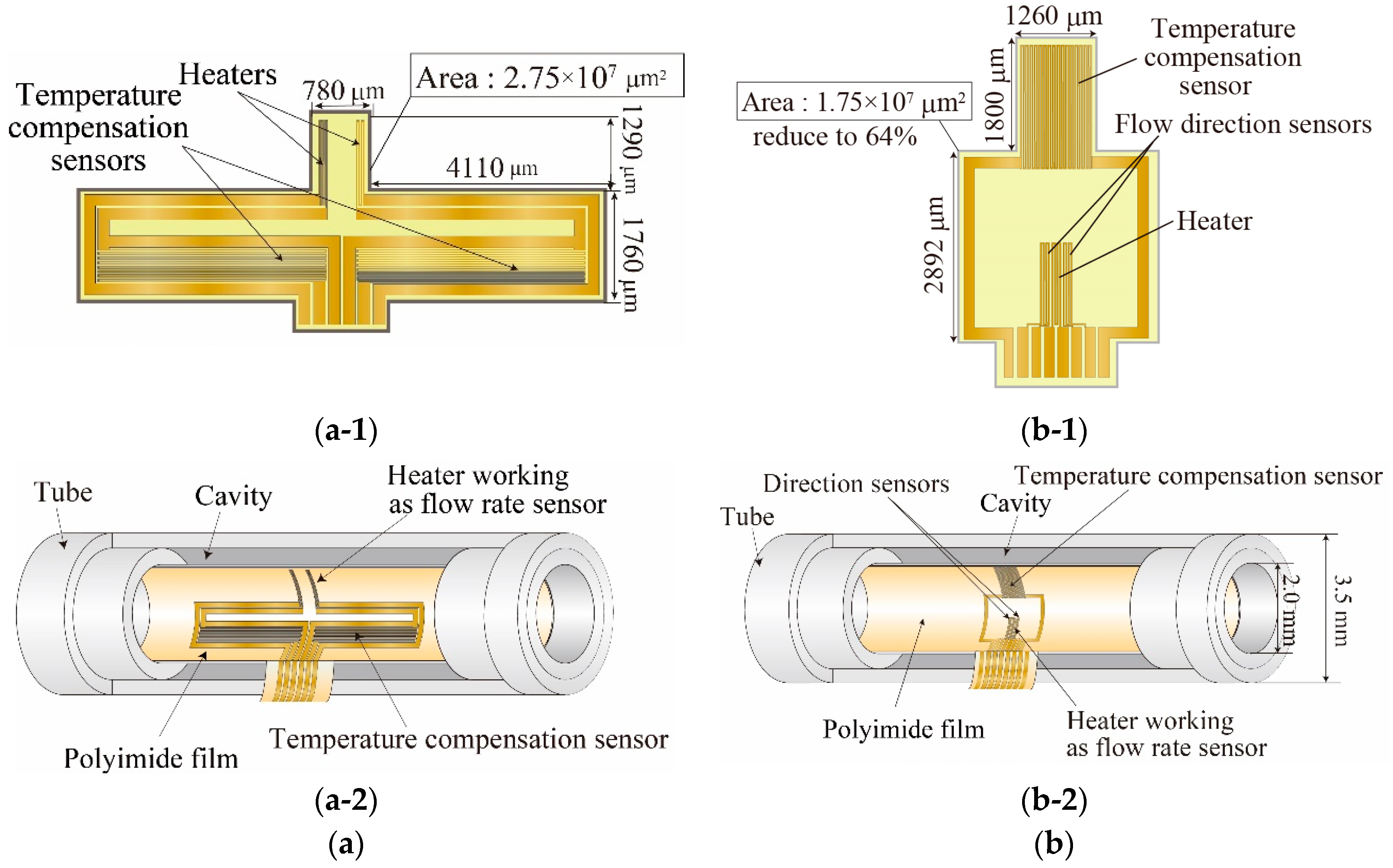
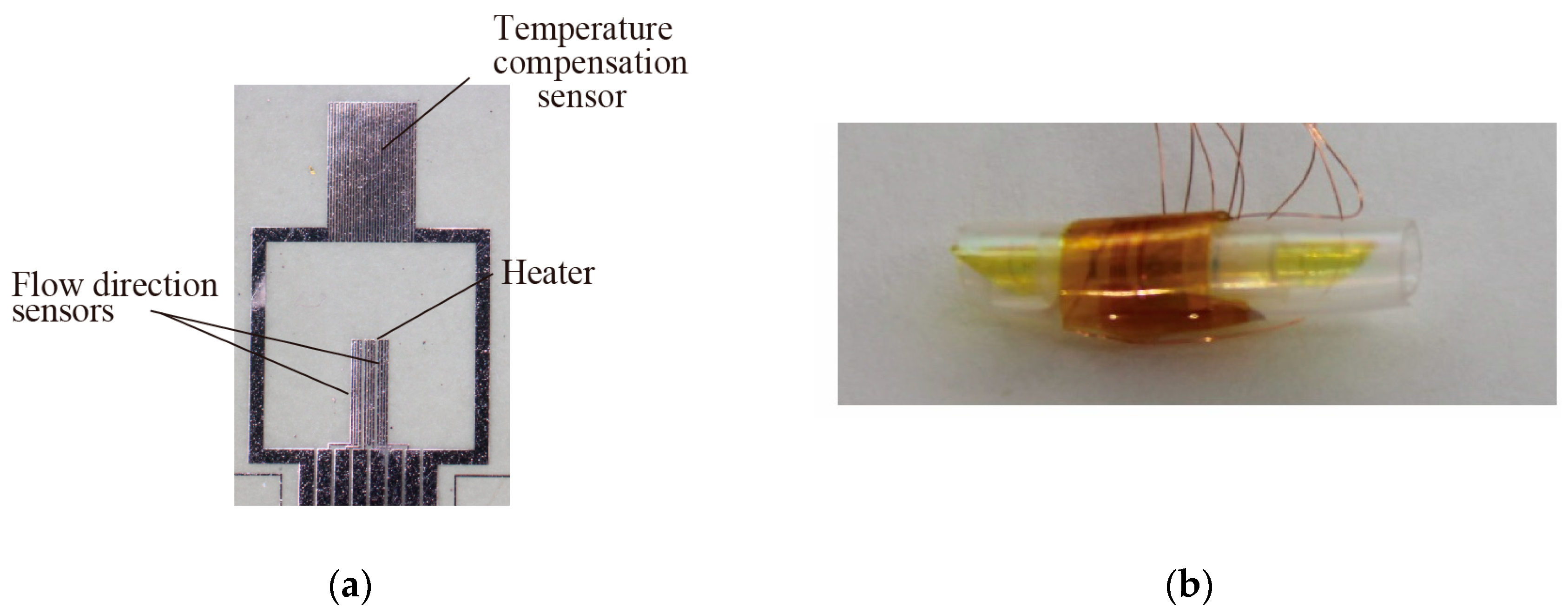
Figure 4.
Fabricated sensor film and tube flow sensor: (a) Sensor elements on polyimide film; (b) Tube flow sensor.
Figure 4.
Fabricated sensor film and tube flow sensor: (a) Sensor elements on polyimide film; (b) Tube flow sensor.

Figure 5.
Relationship between flow rate and sensor output.
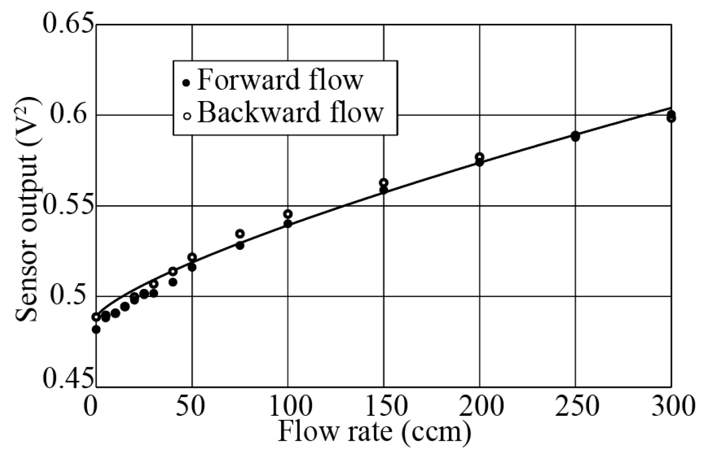
Figure 6.
Effect of flow-direction sensor operation on flow rate measurement.
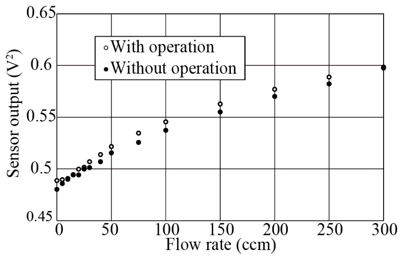
Figure 7.
Effect of airflow temperature change on flow rate measurement.
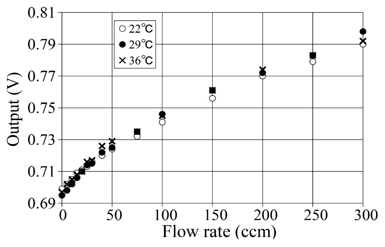
Figure 8.
Subtracted value between two temperature sensors. (Output = temperature sensor 1 − temperature sensor 2).
Figure 8.
Subtracted value between two temperature sensors. (Output = temperature sensor 1 − temperature sensor 2).
Publisher’s Note: MDPI stays neutral with regard to jurisdictional claims in published maps and institutional affiliations. |
© 2017 by the authors. Licensee MDPI, Basel, Switzerland. This article is an open access article distributed under the terms and conditions of the Creative Commons Attribution (CC BY) license (https://creativecommons.org/licenses/by/4.0/).
Share and Cite
MDPI and ACS Style
Mitsunari, Y.; Hasegawa, Y.; Matsushima, M.; Kawabe, T.; Shikida, M. Development of Small-Footprint Thermal Sensor Detecting Airflow at Mouth in Baby. Proceedings 2017, 1, 359. https://doi.org/10.3390/proceedings1040359
AMA Style
Mitsunari Y, Hasegawa Y, Matsushima M, Kawabe T, Shikida M. Development of Small-Footprint Thermal Sensor Detecting Airflow at Mouth in Baby. Proceedings. 2017; 1(4):359. https://doi.org/10.3390/proceedings1040359
Chicago/Turabian StyleMitsunari, Yuki, Yoshihiro Hasegawa, Miyoko Matsushima, Tsutomu Kawabe, and Mitsuhiro Shikida. 2017. "Development of Small-Footprint Thermal Sensor Detecting Airflow at Mouth in Baby" Proceedings 1, no. 4: 359. https://doi.org/10.3390/proceedings1040359