Proceeding Paper

The First Frequency-Modulated (FM) Pitch Gyroscope †

1
Department of Civil and Environmental Engineering, Politecnico di Milano, Milan 20133, Italy
2
Department of Electronics, Information and Bioengineering, Politecnico di Milano, Milan 20133, Italy
3
STMicroelectronics, AMG, Cornaredo 20010, Italy
*
Author to whom correspondence should be addressed.
Presented at the Eurosensors 2017 Conference, Paris, France, 3–6 September 2017.
Proceedings 2017, 1(4), 393; https://doi.org/10.3390/proceedings1040393
Published: 8 August 2017
(This article belongs to the Proceedings of Proceedings of Eurosensors 2017, Paris, France, 3–6 September 2017)

Abstract

:
In this work, the mechanical design and the experimental validation of a micro-electromechanical frequency-modulated (FM) pitch gyroscope are presented. The proposed device is fabricated through the ThELMA © surface micromachining process of STMicroelectronics and it represents, to the authors’ knowledge, the first small-footprint (690 µm × 946 µm) prototype of FM gyroscope able to measure an in-plane angular rate. The measured scale factor, defined as the mean angular gain, equals 0.973 Hz/Hz, in close agreement with theoretical predictions. It depends only on the mass distribution in the mechanical structure and is, consequently, not influenced by environmental fluctuations.

1. Introduction

Producing stable and reliable vibratory micro-electromechanical systems (MEMS) gyroscopes that do not require expensive calibration procedures has proven to be extremely challenging, primarily due to the high sensitivity of the system to fabrication imperfections and environmental changes (e.g., temperature, humidity). Moreover, high sensitivity drift generally precludes their widespread adoption in attractive fields as, e.g., inertial grade navigation and pedestrian dead reckoning.
FM gyroscopes, firstly studied in [1] for yaw measurement, are here proposed as a possible solution, thanks to their ultra-stable, ratiometric scale factor. In FM microgyroscopes the external angular rate modulates the resonance frequency of the micromachined structure, rather than the amplitude of the motion along the sense axis. While amplitude-modulated (AM) operation relies on controlling the displacement of the drive axis and measuring the displacement variation along the sense axis due to the Coriolis’ force, FM operation controls the two axes velocities (both in amplitude and phase) and measures the frequency variation due to the Coriolis’ force. Depending on the phase difference ∆Φ imposed between the driving velocities of the two axes of the gyroscope, there are two different FM schemes (see [1] for more details): Quadrature frequency modulation (QFM: ∆Φ = ±90°) and Lissajous frequency modulation (LFM: ∆Φ = ∆ω·t where ∆ω is the frequency mismatch between the two axes).
In this work, we present the first pitch (or roll) gyroscope based on LFM working principle.

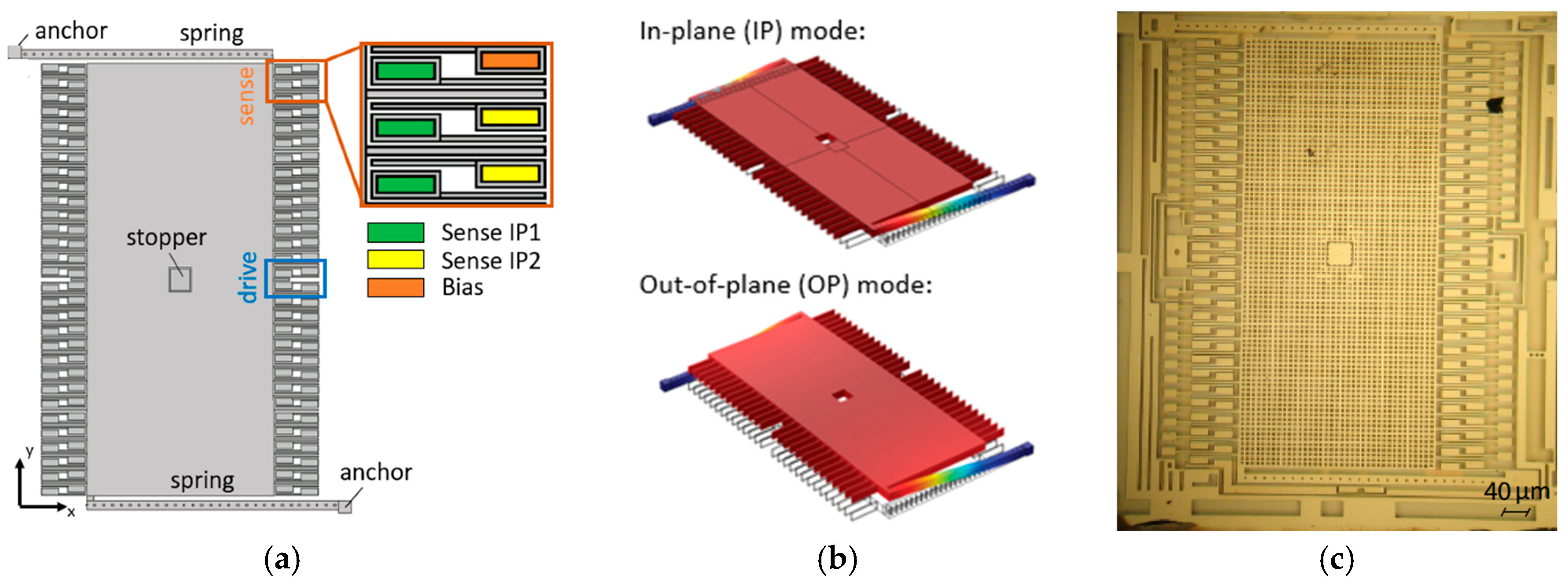
2. Working Principle and Mechanical Design

In order to measure an external angular rate acting along the x-axis, the proof mass is forced to oscillate following two modes (in-plane, IP, and out-of-plane, OP) orthogonal to the angular rate direction at their own resonance frequency with a fixed displacement amplitude through two dedicated sustaining loops (see [2]). Being the two natural frequencies different by design in this LFM pitch gyroscope (see Table 1), the proof mass precesses in the yz-plane following the so-called Lissajous trajectory. When an angular rate Ω x acts along the x-direction, the Coriolis’ force couples the two modes (y- and z-) inducing an apparent resonance frequency variation on each axis [1]:
ω y = ω 0 y α x y z Ω x v z v y sin ( Δ Φ y z ) ,
ω z = ω 0 z α x z y Ω x v y v z sin ( Δ Φ y z ) ,
where     α x y z ,     α x z y are the angular gains (each one equal to one for a point proof mass), ω 0 y ,     ω 0 z are the natural frequencies of the two modes, v z ,     v y are the velocity amplitudes along the z- and y- axis, respectively, and Δ Φ y z is the phase difference between the displacements of the two axes. As the nominal frequencies of the two oscillators are different, the angular rate, measured at electrodes fixed to the rotating frame, gets frequency-modulated at the frequency mismatch given by   ( ω y ω z ) / 2 π . In this way, resonance frequency drifts, e.g., due to temperature variations, are not equivocated as angular rate signals.
By assuming an ideal readout electronics, i.e., with perfect velocity amplitude control, v y = v z , control-related errors are minimized, and an ultra-stable, ratiometric scale factor is obtained [3]: from Equation (1) (or (2)), one obtains a scale factor of the LFM gyroscope equal to the angular gain, α x z y   ( or α x y z ) , a pure geometric quantity that takes into account the coupling between the modal masses of the two drive modes due to the Coriolis’ force. Furthermore, if the sum of Equations (1) and (2) is considered, the stability of the scale factor against practical control-related errors is improved thanks to the effects of summing the velocity amplitudes ratios.
Note that in Equations (1) and (2) cross-stiffness and cross-damping terms are neglected for the sake of simplicity, however the full expression can be easily obtained from the dynamic equations of motion as done in [1] for a yaw FM gyroscope.
The mechanical structure of a FM pitch gyroscope must, then, be able to translate along the IP and the OP directions simultaneously. The chosen implementation is shown in Figure 1a. The device comprises a rectangular proof mass suspended by two thick elongated springs that allow both the IP and the OP translations. Bottom electrodes (located under the proof mass at a 1.8 µm gap) and IP parallel plates (shown in the inset of Figure 1a) are adopted for the OP and the IP actuation/detection respectively. Tuning electrodes are also provided among bottom electrodes to compensate mismatch variations due to fabrication imperfections. Note that the IP mode works with a differential drive/sense scheme, while in the OP direction only single-ended driving/reading scheme is allowed due to fabrication constraints. In order to avoid electrostatic nonlinearities that could degrade the device performance, electrodes are sized to have the target displacements along the two axes in the range of hundreds of nm (100 nm and 200 nm for OP and IP modes respectively).
Figure 1b shows the first two modes of the structure (translations along the y- and z-axis), computed by COMSOL Multiphysics ©. Figure 1c shows instead the optical microscope image of a prototype fabricated by the ThELMA © surface micromachining process of STMicroelectronics. Table 1 summarizes the mechanical parameters of the structure, computed through different Finite Element analyses. The angular gains, α x z y   and α x y z , of the proposed gyroscope are close to one being the dynamic behavior of the mechanical structure close to that of a point mass.

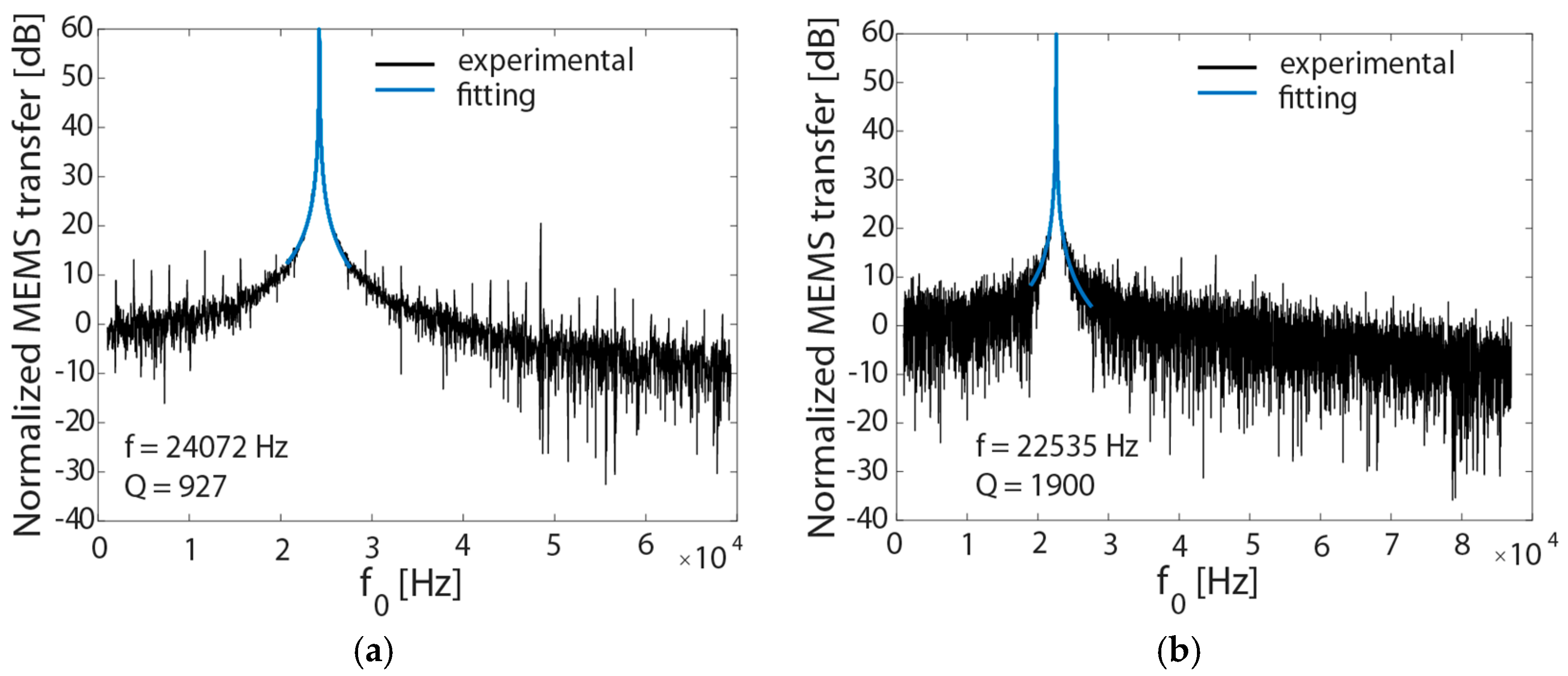
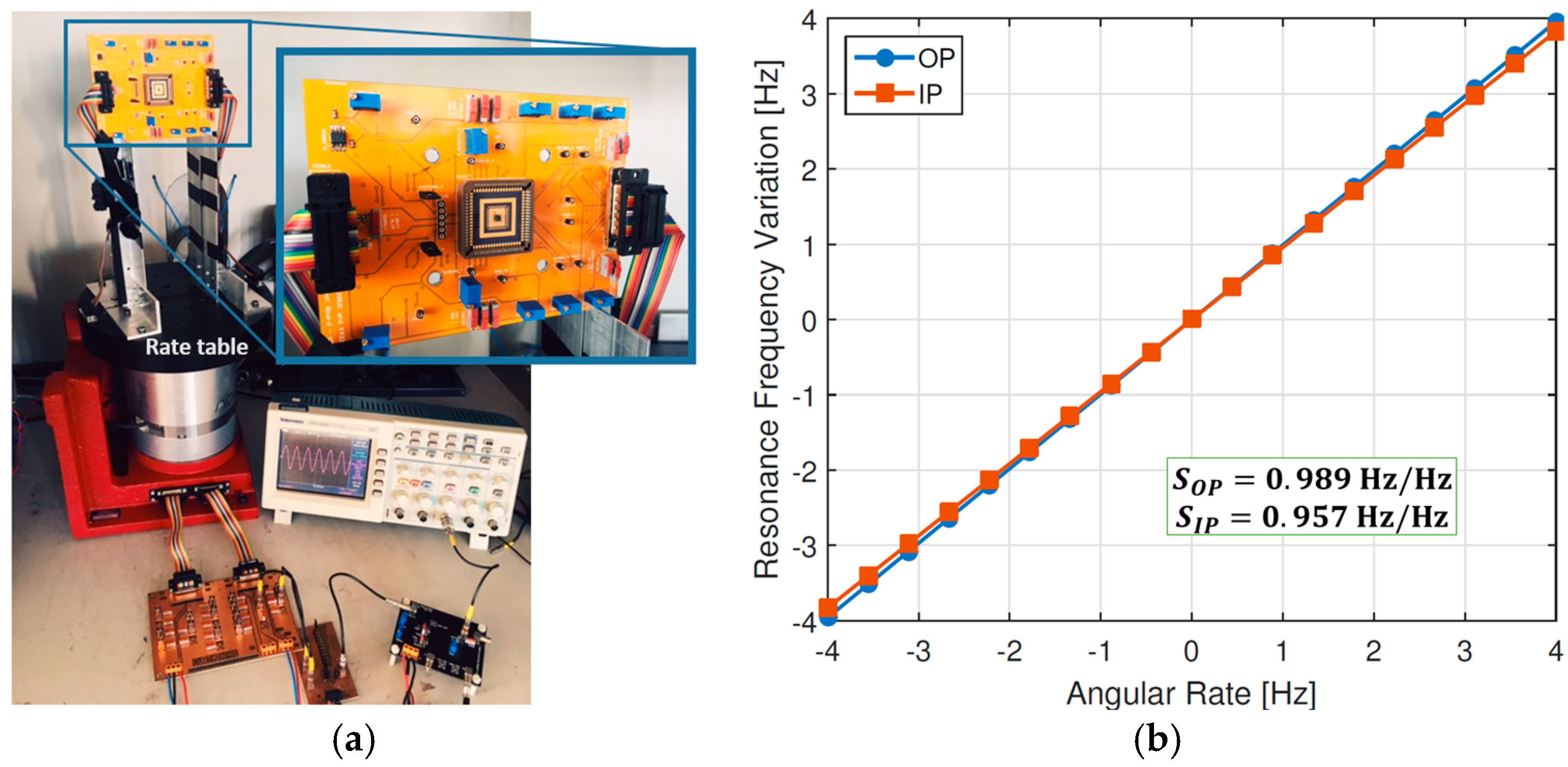
3. Experimental Measurements

The first experimental characterization of the proposed device has been carried out through the MEMS Characterization Platform from ITmems srl, a tool specifically developed for testing capacitive accelerometers and gyroscopes. The natural frequencies and the quality factors of the two modes of the gyroscope are obtained by fitting their frequency responses (Figure 2). A good agreement in terms of quality factor is obtained, while the differences in terms of frequencies can be ascribed to an over etch larger than the target value.
The pitch gyroscope has been then coupled to a custom low-power and low-noise integrated circuit previously tested on FM yaw gyroscopes [2]. By testing the device on a rate table, as shown in Figure 3a, a scale factor of 0.973 Hz/Hz is obtained. The value is taken as the average of the OP and IP sensitivities (SOP and SIP respectively) shown in Figure 3b, in close agreement with theoretical predictions of 0.975 reported in Table 1.

4. Conclusions

The first FM pitch gyroscope has been designed, fabricated by the ThELMA© surface micromachining process developed by STMicroelectronics and experimentally tested. A good agreement between numerical predictions and experimental measurements is found, especially in terms of quality factor and scale factor.
The proposed structure, made by only one mass and two springs, can be considered as the simplest implementation of a MEMS FM pitch gyroscope. Its dynamic behavior can be, in fact, fully described by the equations of motion written for a point mass and thus the angular gain approaches the ideal value of one. Decoupling mechanisms between the modes would improve the overall performances of the device (e.g., reducing quadrature and cross-talk) but would also reduce the scale factor. The trade-off between these two quantities must be taken into account in order to optimize the mechanical design of a FM pitch gyroscope.
The authors are currently working (i) on a novel decoupled and differential design of the FM pitch gyroscope, with the purpose of improving the acceleration rejection and quadrature decoupling; and (ii) on a triaxial FM gyroscope [5].

Author Contributions

V.Z. and C.C. conceived the mechanical design of the FM pitch gyroscope. P.M. and G.L. performed the experimental measurements. P.M., G.M. and G.L. developed the integrated circuit. G.L., C.C., A.C., A.B., A.L.L., A.T., S.F. and L.F. oversaw the research, provided guidance and discussed the results and implications at all stages. V.Z. and C.C. wrote the manuscript and all authors edited the manuscript.

Acknowledgments

The authors gratefully acknowledge B.E. Boser and D.A. Horsley for the helpful scientific discussions.

Conflicts of Interest

The authors declare no conflict of interest.

References

  1. Kline, M.H.; Yeh, Y.-C.; Eminoglu, B.; Najar, H.; Daneman, H.; Horsley, D.A.; Boser, B.E. Quadrature FM gyroscope. In Proceedings of the 2013 IEEE 26th International Conference on Micro Electro Mechanical Systems (MEMS), Taipei, Taiwan, 20–24 January 2013; pp. 604–608. [Google Scholar]
  2. Minotti, P.; Mussi, G.; Dellea, S.; Bonfanti, A.; Lacaita, A.L.; Langfelder, G.; Zega, V.; Comi, C.; Facchinetti, S.; Tocchio, A. A 160 µA, 8 mdps/Hz1/2 frequency modulated MEMS yaw gyroscope. In Proceedings of the 2017 IEEE International Symposium on Inertial Sensors and Systems (INERTIAL), Kauai, HI, USA, 28–30 March 2017; pp. 1–4. [Google Scholar]
  3. Izyumin, I.I.; Kline, M.H.; Yeh, Y.C.; Eminoglu, B.; Ahn, C.H.; Hong, V.A.; Yang, Y.; Ng, E.J.; Kenny, T.W.; Boser, B.E. A 7 ppm, 6 deg/hr frequency-output MEMS gyroscope. In Proceedings of the 2015 IEEE International Conference on Micro Electro Mechanical Systems (MEMS), Estoril, Portugal, 18–22 January 2015; pp. 33–36. [Google Scholar]
  4. Frangi, A.; Fedeli, P.; Laghi, G.; Langfelder, G.; Gattere, G. Near vacuum gas damping in MEMS: Numerical modeling and experimental validation. J. Microelectromech. Syst. 2016, 25, 890–899. [Google Scholar] [CrossRef]
  5. Tocchio, A.; Falorni, L.; Comi, C.; Zega, V. Frequency Modulation MEMS Triaxial Gyroscope. Deposited Patent No. 102016000106928, 24 October 2016. [Google Scholar] [CrossRef]
Figure 1. (a) Schematic view of the proposed FM pitch gyroscope. The actuation and detection schemes for the IP mode is also shown; (b) The first two modes of the structure: the contour of the displacement field is shown in color; (c) Optical microscope image of a fabricated FM pitch gyroscope.
Proceedings 01 00393 g001
Figure 2. Experimental measurement of the quality factor and of the natural frequencies of the (a) OP and (b) IP modes of the FM pitch gyroscope.
Proceedings 01 00393 g002
Figure 3. (a) Experimental set-up: the MEMS and the IC are stacked and wire-bonded in a socket (close-up view), and then placed on the rate table; (b) Measured resonance frequency variation as a function of the rate, for both OP and IP modes. Scale factor errors are greatly reduced when measuring the sum of both axes variations [2].
Proceedings 01 00393 g003
Table 1. Mechanical properties of the proposed FM pitch gyroscope computed through finite element (FE) simulations.
IP ModeOP Mode
Natural frequency24,157 Hz26,250 Hz
Angular Gain0.97530.9759
Quality factor (see [4])1800900
Modal Mass14 nKg13 nKg
Publisher’s Note: MDPI stays neutral with regard to jurisdictional claims in published maps and institutional affiliations.

