A Lorentz Force Actuated Continuous Deformable Polymer Mirror for Wavefront Control †


Department of Electrical and Computer Engineering, University of Manitoba, Winnipeg, MB, Canada
*
Author to whom correspondence should be addressed.
†
Presented at the Eurosensors 2017 Conference, Paris, France, 3–6 September 2017.
Proceedings 2017, 1(4), 554; https://doi.org/10.3390/proceedings1040554
Published: 11 August 2017
(This article belongs to the Proceedings of Proceedings of Eurosensors 2017, Paris, France, 3–6 September 2017)
Abstract
:This paper describes MEMS deformable polymer mirror system for adaptive optics application. This system employs a 4 µm thick SU-8 membrane with a stress balanced double side aluminum coating as a mirror element. Underlying Lorentz actuators are used to control the surface topography of the mirror, enabling optical wavefront correction. Compared to electrostatic, piezoelectric, and thermal actuators, the Lorentz actuators offer low voltage drive (<1 V), high deflection, and bi-directional motion. Mirror deflection of up to 45 µm was demonstrated, with lower deflections of 10 µm achieved with actuator heating below 10 °C.
1. Introduction
Miniaturized adaptive optics (AO) systems have gained much attention over the past decades. AO systems can correct distorted wavefront and are being explored for applications such as earth-based telescopes [1,2,3], microscopy [4], retinal imaging [5,6], optical communication [7], and high energy lasers [8]. AO systems employ 100’s to 1000’s actuators to manipulate a topology of mirror surface to actively compensate the distorted image wavefront. MEMS fabrication technology has enabled the miniaturization of DMs, reducing power consumption and large space occupancy, and have enabled batch fabrication of numerous actuator elements together. This has provided high reliability of the manufacturing process compared to classical macroscopic actuators.
Development of AO technology with sufficient mirror deformation and low driving voltage has been focused many research groups. However, these systems commonly use electrostatic and piezoelectric transducing mechanism, which suffer from limited stroke, since as the stroke increases, the actuation voltage rises. The needed high voltage driver takes large space, requires high power consumption and increases the overall complexity of the system. A commercially available MEMS-based deformable mirror was introduced by a Boston Micromachines Inc. (Cambridge, MA, USA) [3]. The deformable membrane mirror is made of rigid polysilicon membrane operated by electrostatic transducer. The maximum mirror stroke was 1.9 µm, requiring a high voltage of 241 V. To make an additional driving voltage reduction, a flexible organic polymer was employed. An epoxy-based SU-8 and polyimide were combined with electrostatic actuator and reported in [9,10]. The highest strokes of both deformable mirrors were 12 µm at 220 V for [9] and 39 µm at 195 V for [10]. In comparison, piezoelectric and thermal actuators are known to have lower drive voltages. The piezoelectric unimorph microactuator of [11] employed a 100 µm thick single crystalline silicon mirror, and offered 7.4 µm stroke at 100 V.
In contrast to the above efforts, Lorentz actuators have many benefits, including low operation voltage and bi-directional out-of-plane motion with no magnetic hysteresis effect. This allows the correction of surface flatness issues due to gravity-induced deformation on mirror membranes. These advantages, combined with a simple actuator design, fast response, reasonable power consumption, make them ideal for large stroke applications. A Lorentz actuator array with large stroke and thermal stability was presented in [12]. The demonstrated actuators showed a deflection of ±150 µm with ±15 mA current in a 0.48 T magnetic field.
In this paper, we demonstrate a deformable polymer mirror (DPM) system. This system is formed from two substrate wafers. The first contains the Lorentz force based actuator array, and it is bonded to the second substrate containing the metallized DPM.
2. Design and Fabrication
The design concept and working principle of the Lorentz actuators are shown in Figure 1a. The single crystal silicon actuators consist of a thick (rigid) crossbar (2080 µm long, ~26 μm thick) that is supported by flexible serpentine springs (~3 μm thick) on either side. Each actuator is sputter coated with 1.5 µm thick aluminum, with ~30 Ω resistance. The actuators function by Lorentz force coupling between an electric current flowing in the crossbar and a nearby magnet. A 5 × 5 actuator array (Figure 1b) was enabled by implementing narrow and rigid support rails that anchor the actuators to the substrate. The actuator array was formed from a double side polished silicon wafer with three KOH etch processes and finally bonded to the mirror substrate.
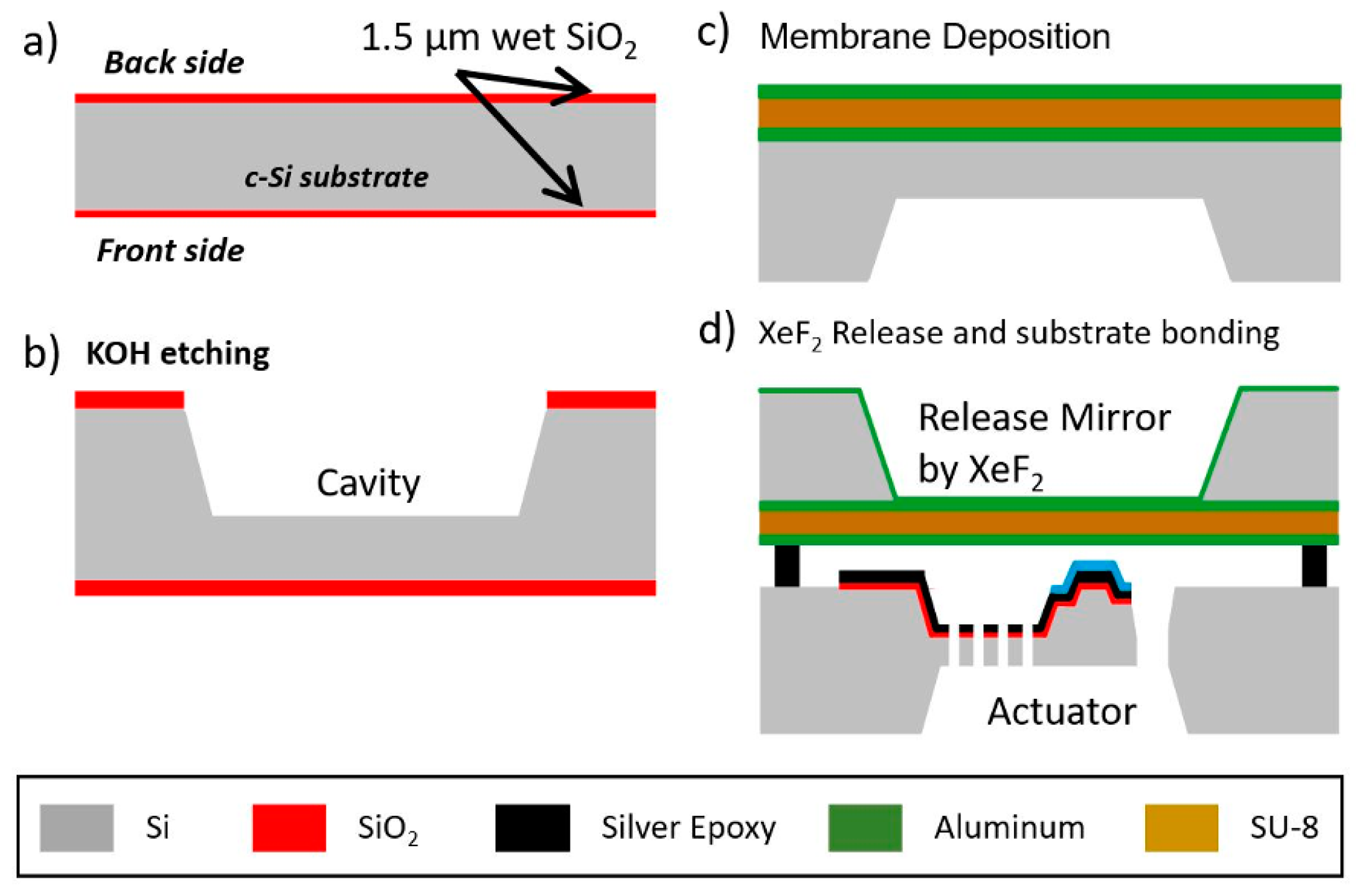
The DPM is fabricated on a second substrate wafer. A 1.5 µm thick wet thermal oxide is grown on the wafer to be used as a KOH etch mask (Figure 2a). Openings are made in the backside oxide using a 10:1 buffered oxide etchant (BOE). Exposed silicon is etched in 30% KOH at 80 °C until a 30 µm silicon membrane remains (Figure 2b). After the backside etch, the front side oxide is removed using BOE. The thick 30 µm silicon membrane is used as the base for fabrication of the mirror, since its large thickness keeps it unbent by stress during the following steps. The front side is coated with a tri-layer of aluminum/SU-8/aluminum (see Figure 2c). The aluminum is 250 µm thick and deposited by thermal evaporation. Then, SU-8-2025 (MicroChem, USA) is spin coated to a thickness of 4 µm to serve as the flexible membrane. To further crosslink the SU-8, a hard bake is done at 150 °C for 60 min. Finally, 250 nm aluminum is deposited. By sandwiching the SU-8 between the two aluminum layers, stress is balanced, maintaining flatness. Finally, a XeF2 gas etch is used to remove the 30 µm underlying silicon, freeing the mirror. Then plasma cleaning is done to the mirror surface in order to remove any remaining silicon. After mirror fabrication, the actuator substrate is bonded to the mirror substrate using silver epoxy (Figure 2d). It is cured at 80 °C for 3 h. Figure 3 shows a picture of the bonded DPM system.
3. Result and Discussion
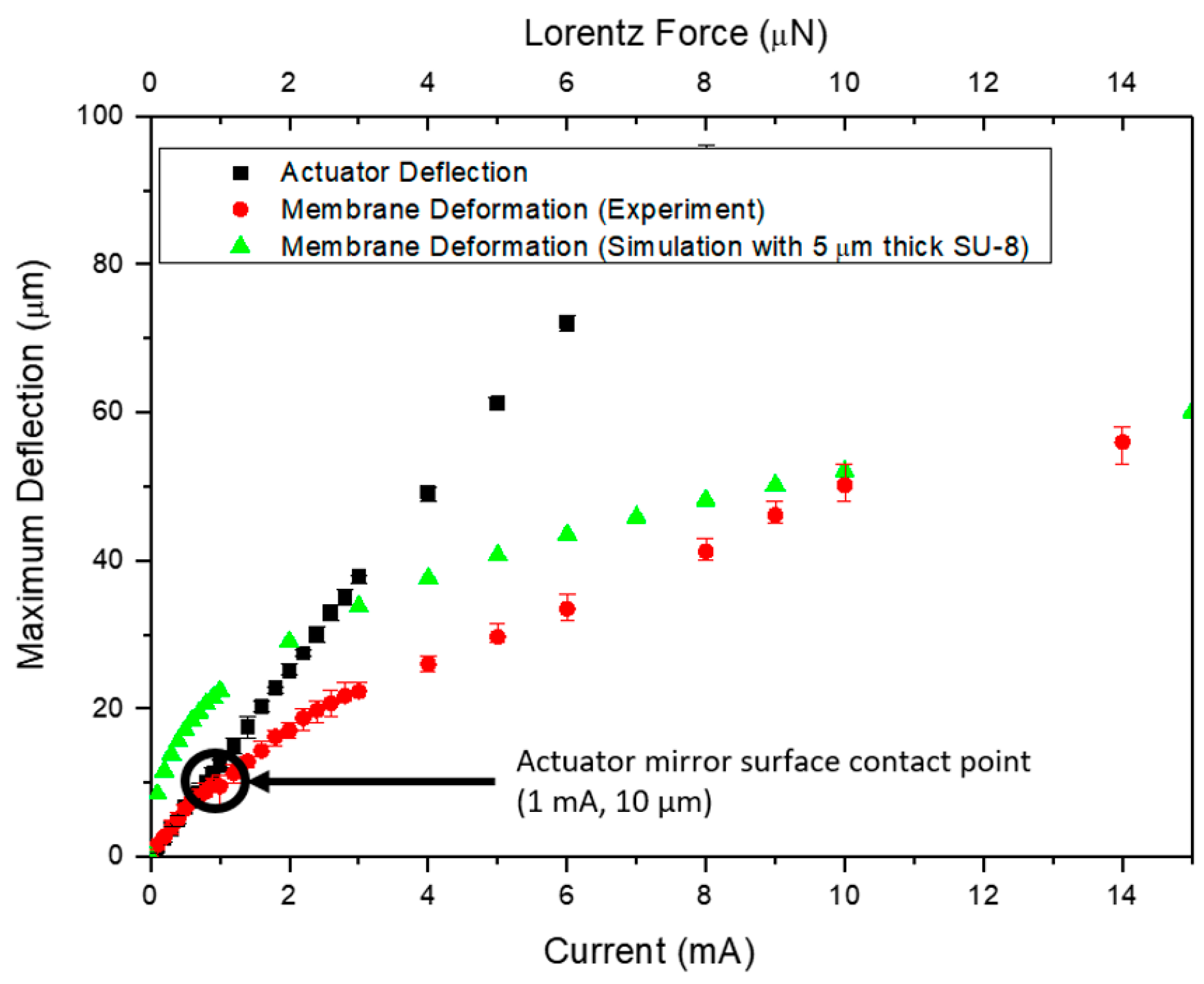
The performance of the DPM system was measured experimentally and compared with simulations done using COMSOL Multiphysics. Figure 4 plots the results.
The black squares on Figure 4 are the measured deflection of the Lorentz actuators alone, without being bonded to the DPM, in the presence of 0.35 Tesla magnetic field. The red squares are the measured deflection of the DPM when pushed by the Lorentz actuators. It should be mentioned that after bonding to the mirror substrate, the actuators were spaced 10 µm below the DPM. Accordingly, the first 10 µm of motion is for the actuators moving alone, while subsequent motion are the actuators pushing against the DPM. The green triangles are the simulated deflection of the DPM, for the same actuator current values (and so Lorentz force) of the experimental data of the red circles. Data is taken up to 14 mA current, to maintain actuator temperature below 100 °C. For a moderate mirror deflection of 10 µm, the heating of the actuator is only 10 °C.
Acknowledgments
This research was financially supported by the Natural Research Council (NRC) of Canada and the University of Manitoba Graduate Fellowship (UMGF).
Conflicts of Interest
The authors declare no conflict of interest.
References
- Madec, P.-Y. Overview of deformable mirror technologies for adaptive optics and astronomy. Proc. SPIE 8447 Adapt. Opt. Syst. III 2012, 844705. [Google Scholar] [CrossRef]
- Wallace, B.P.; Hampton, P.J.; Bradley, C.H.; Conan, R. Evaluation of a MEMS deformable mirror for an adaptive optics test bench. Opt. Express 2006, 14, 10132–10138. [Google Scholar] [CrossRef] [PubMed]
- Perreault, A.; Bifano, T.G.; Levine, B.M.; Horenstein, M.N. Adaptive optic correction using microelectromechanical deformable mirrors. Opt. Eng. 2002, 41, 561–566. [Google Scholar] [CrossRef]
- Bifano, T. Shaping light: MOEMS deformable mirrors for microscopes and telescopes. Proc. MEMS Adapt. Opt. IV 2010, 7595, 759502. [Google Scholar] [CrossRef]
- Vera-Díaz, F.A.; Doble, N. The Human Eye and Adaptive Optics in Topics in Adaptive Optics; InTech Open Access Publisher: Rijeka, Croatia, 2012; pp. 119–150. [Google Scholar] [CrossRef]
- Liang, J.; Williams, D.R.; Miller, D.T. Supernormal vision and high-resolution retinal imaging through adaptive optics. J. Opt. Soc. Am. 1997, 14, 2884–2892. [Google Scholar] [CrossRef] [PubMed]
- Wilson, K.E.; Wright, M.W.; Lee, S.; Troy, M. Adaptive optics for daytime deep space laser communications to Mars. In Proceedings of the Digest of the LEOS Summer Topical Meetings, San Diego, CA, USA, 25–27 July 2005. [Google Scholar] [CrossRef]
- Fugate, R.Q. Laser beacon adaptive optics for power beaming applications. In Proceedings of the SPIE 2121, Laser Power Beaming, Los Angeles, CA, USA, 1 May 1994; pp. 68–76. [Google Scholar]
- Friese, C.; Zappe, H. Deformable Polymer Adaptive Optical Mirrors. J. Microelectromech. Syst. 2008, 17, 11–19. [Google Scholar] [CrossRef]
- Lin, P.-Y.; Hsieh, H.-T.; Su, G.-D.J. Design and fabrication of a large-stroke MEMS deformable mirror for wavefront control. J. Opt. 2011, 13, 055404. [Google Scholar] [CrossRef]
- Ma, J.; Liu, Y.; Chen, C.; Li, B.; Chu, J. Deformable mirrors based on piezoelectric unimorph microactuator array for adaptive optics correction. Opt. Commun. 2011, 284, 5062. [Google Scholar] [CrossRef]
- Park, B.; Afsharipour, E.; Chrusch, D.; Shafai, C.; Andersen, D.; Burley, G. Large Displacement Bi-Directional Out-of-Plane Lorentz Actuator Array for Surface Manipulation. J. Micromech. Microeng. 2017, in press. [Google Scholar] [CrossRef]
Figure 1.
(a) Design of Lorentz force actuator and force relationship. (b) Photo of the fabricated 5 × 5 actuator array.
Figure 1.
(a) Design of Lorentz force actuator and force relationship. (b) Photo of the fabricated 5 × 5 actuator array.
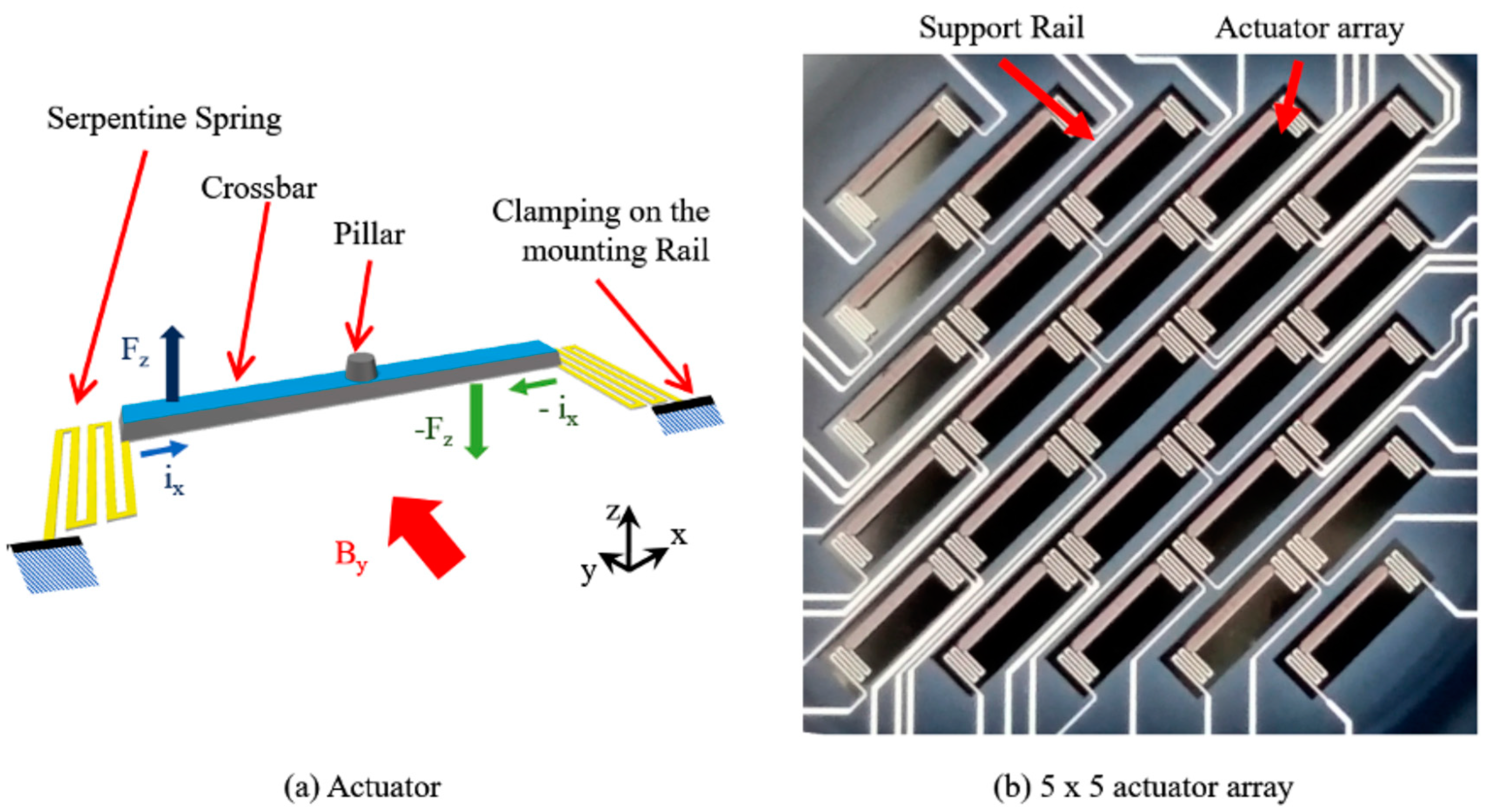
Figure 2.
Mirror fabrication process.

Figure 3.
Photograph of the Al/SU-8/Al mirror attached to the actuator substrate.
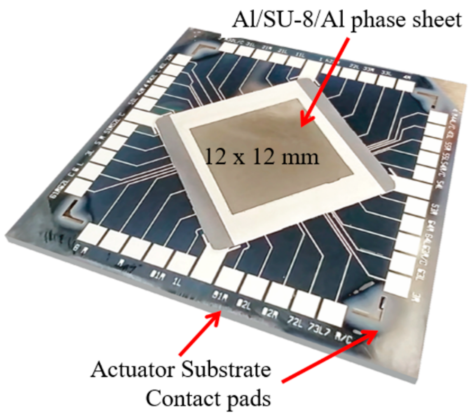
Figure 4.
Measured and simulated DPM stroke versus current compared to actuator deformation.
Publisher’s Note: MDPI stays neutral with regard to jurisdictional claims in published maps and institutional affiliations. |
© 2017 by the authors. Licensee MDPI, Basel, Switzerland. This article is an open access article distributed under the terms and conditions of the Creative Commons Attribution (CC BY) license (https://creativecommons.org/licenses/by/4.0/).
Share and Cite
MDPI and ACS Style
Park, B.; Afsharipour, E.; Shafai, C. A Lorentz Force Actuated Continuous Deformable Polymer Mirror for Wavefront Control. Proceedings 2017, 1, 554. https://doi.org/10.3390/proceedings1040554
AMA Style
Park B, Afsharipour E, Shafai C. A Lorentz Force Actuated Continuous Deformable Polymer Mirror for Wavefront Control. Proceedings. 2017; 1(4):554. https://doi.org/10.3390/proceedings1040554
Chicago/Turabian StylePark, Byoungyoul, Elnaz Afsharipour, and Cyrus Shafai. 2017. "A Lorentz Force Actuated Continuous Deformable Polymer Mirror for Wavefront Control" Proceedings 1, no. 4: 554. https://doi.org/10.3390/proceedings1040554