Proceeding Paper

Bulk PZT Cantilever Based MEMS Acoustic Transducer for Cochlear Implant Applications †

1
METU-MEMS Research and Application Center, Middle East Technical University, Ankara, Turkey
2
Micro Nano Technology Graduate Program, Middle East Technical University, Ankara, Turkey
3
Department of Electrical and Electronics Engineering, Middle East Technical University, Ankara, Turkey
*
Author to whom correspondence should be addressed.
Presented at the Eurosensors 2017 Conference, Paris, France, 3–6 September 2017.
Proceedings 2017, 1(4), 584; https://doi.org/10.3390/proceedings1040584
Published: 11 August 2017
(This article belongs to the Proceedings of Proceedings of Eurosensors 2017, Paris, France, 3–6 September 2017)

Abstract

:
This paper presents the first acoustic experimental results of a MEMS based bulk piezoelectric transducer for use in fully implantable cochlear implants (FICI). For this purpose, the transducer was attached onto an acoustically vibrating membrane. Sensing and energy harvesting performances were measured using neural stimulation and rectifier circuits, respectively. The chip has a 150 Hz bandwidth around 1800 Hz resonance frequency that is suitable for mechanical filtering as a sensor. As an energy harvester, bulk piezoelectric transducer generated a rectified power of 16.25 μW with 2.47 VDC with 120 dB-A sound input at 1780 Hz. Among other MEMS acoustic energy harvesters in the literature, reported transducer has the highest power density (1.5 × 10⁻³ W/cm3) to our knowledge.

1. Introduction

Cochlea is a key organ in the inner ear which converts the mechanical waves of the incoming sound into electrical signals for the auditory nerves. Any damage in cochlea would result problems with the sensorineural connections in the inner ear and cause severe hearing loss. There are approximately 360 million people living with disabling hearing loss greater than 40 dB SPL (sound pressure level) as of 2015 [1]. Cochlear implants (CI) are used by such patients to bypass the damaged hair cells or other components of cochlea and directly stimulate the nerve cells. However, current state of the art CI systems have several drawbacks such as frequent battery replacement requirement or risk of external components damage under water. Fully implantable CI systems have the potential to eliminate many of the problems, but a reliable internal power source and an implantable acoustic sensor are the main bottlenecks. One alternative is powering the implant with the incoming acoustic wave using an energy harvester.
Previous research on the acoustic piezoelectric energy harvesters focuses on diaphragm structures with a cavity to scavenge sound power. Up to 9.8 nW/cm2 of power density was reported at 100 dB-SPL using thin film lead-zirconate-titanate (PZT) MEMS acoustic energy harvesters [2]. A piezoelectric cantilever array reported by Jang et al. uses thin film AlN piezoelectric transducers [3], but the generated voltage is on the order of 50 μV and requires an external power source for neural stimulation. In a previous study of our group, Beker et al. theoretically investigated the bulk piezoelectric energy harvesters attached on a flat ear drum model and verified the efficiency of using bulk PZT for power generation in CIs [4].
This study presents MEMS piezoelectric cantilever structures on a membrane as an acoustic transducer. Both energy harvesting and acoustic sensing characteristics were determined.

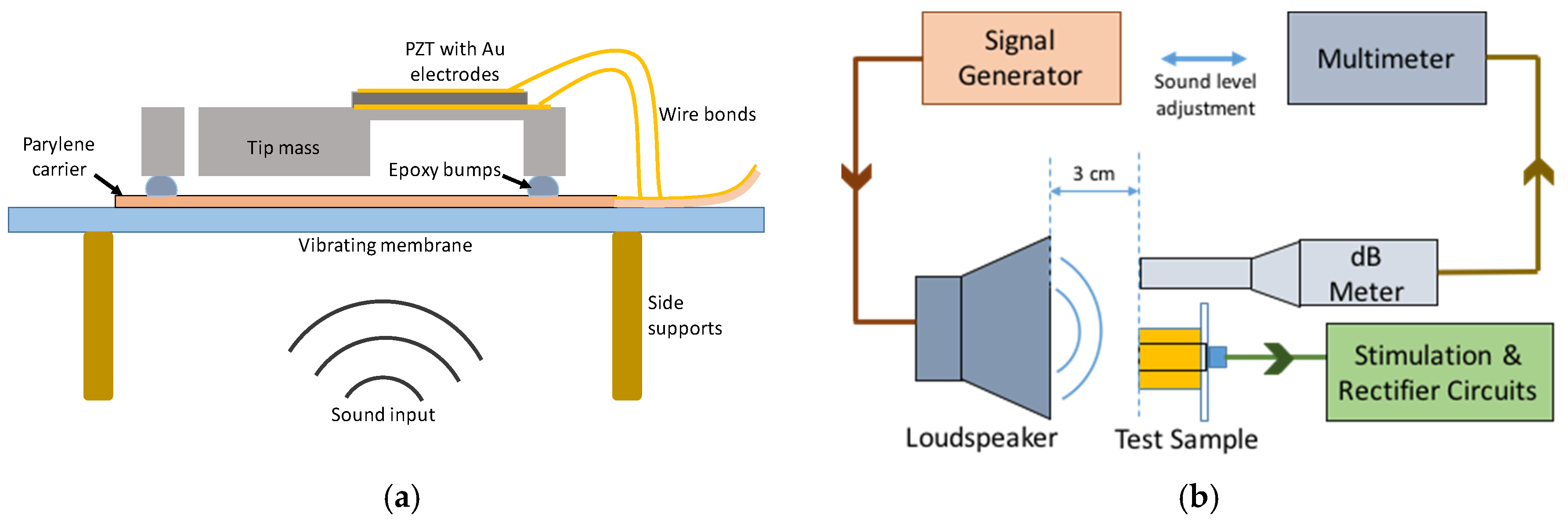
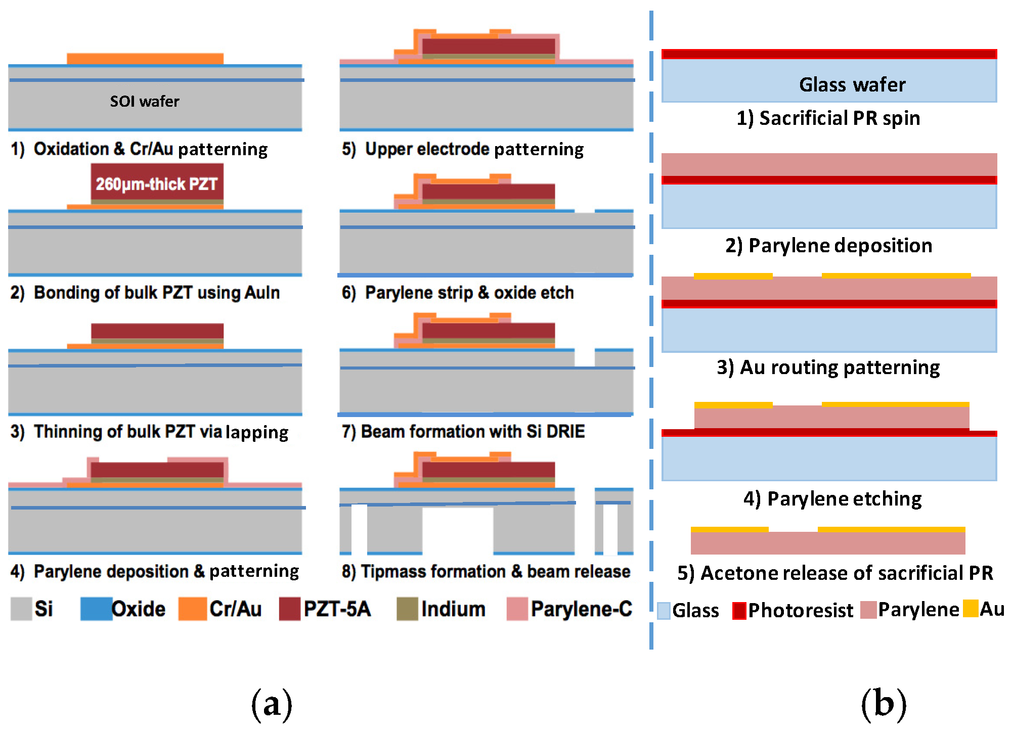
2. Materials and Methods
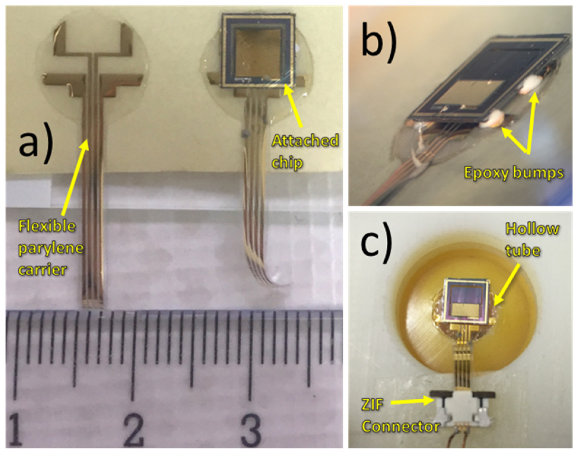
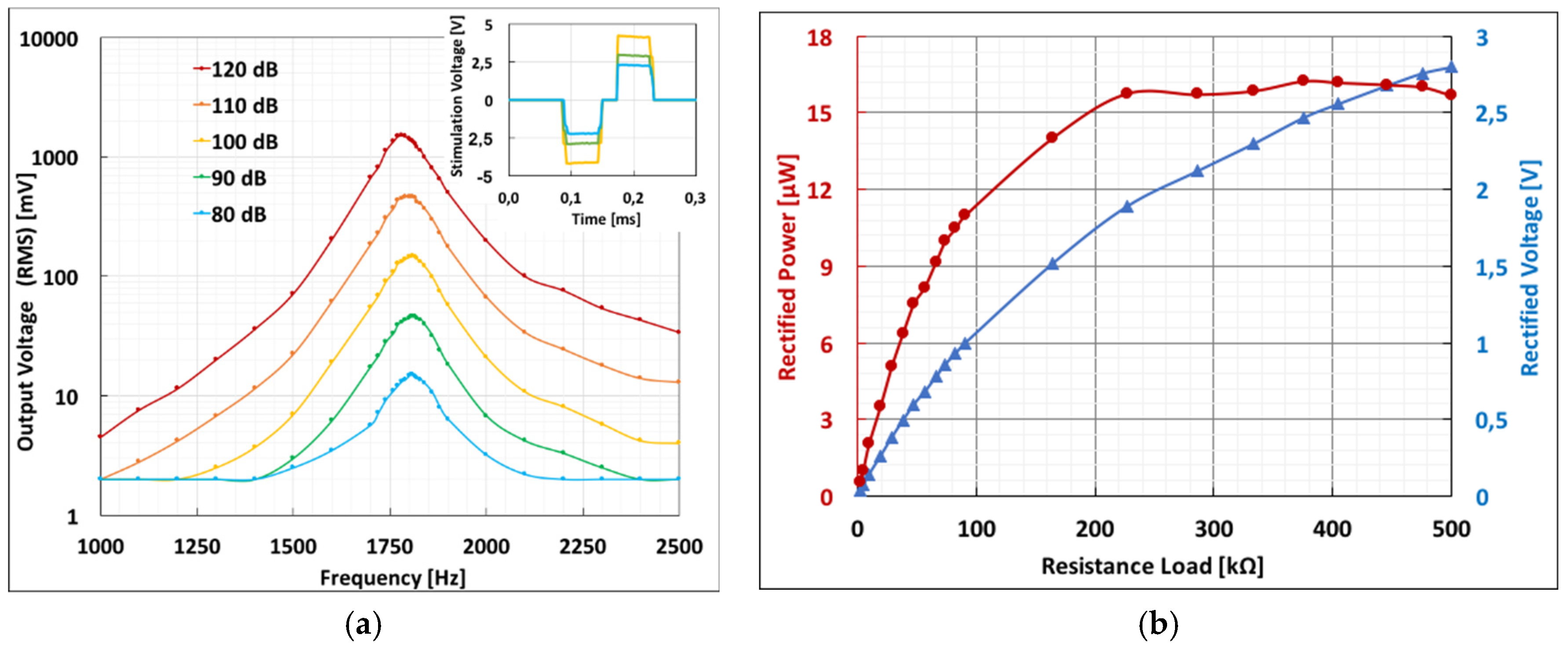
Many of the MEMS piezoelectric energy harvesting systems in the literature are composed of a cantilever structure with a tip mass at the free end [4]. Base of the cantilever is attached to a vibration source and a piezoelectric layer is placed on the cantilever. In our case, for using the piezoelectric harvester with an acoustic source, the harvester chip is attached on a flexible membrane similar to tympanic membrane in actual ear.
Figure 1 shows the schematics of proposed system attached on a membrane and the acoustic test setup. Sound pressure at the inlet of the test canal is measured with a sound level meter. Calibration of the loudspeaker and dB-meter were done in an anechoic room. Signal generator output is adjusted for each frequency. A circuit with custom off-chip components and a microcontroller is used for generating biphasic neural stimulation signal with the piezoelectric transducer output. A simple rectifier circuit is used for power generation.
Figure 2 shows the fabrication process flows of the transducer that is based on the SOI-wafer technology (2a) and the parylene carrier (2b). Bulk PZT chip is bonded on an SOI-wafer by AuIn transient liquid phase (TLP) bonding and, subsequently thinned down to 50 μm by lapping. Active and handle layers of the SOI wafer (30 μm and 300 μm) define the cantilever and tip mass thicknesses, respectively. DRIE is used for cantilever formation. A parylene layer (20 μm) with gold contacts is used as carrier.
The piezoelectric chip is fixed with epoxy on the flexible parylene carrier prior to attaching the device on the vibrating membrane. Epoxy bumps prevent the tip mass from contacting the membrane surface while vibrating. Electrical connections are established using wire bonding and conductive epoxy. A ~40 μm thick parylene film is used as the ear drum mimicking vibrating membrane. The membrane is placed at the end of a hollow tube with 9 mm diameter and 3.5 cm length, similar to ear drum and ear canal dimensions respectively. Figure 3 shows the actual test chip attached on parylene carrier and the vibrating membrane on hollow tube.

3. Results

Acoustic tests at different sound levels and resistive loading conditions were done. Figure 4 shows the overall test results. 1.51 Vrms output was obtained under 120 dB-A acoustic input at the inlet of the canal around 1780 Hz resonance frequency with a 150 Hz bandwidth. Generated voltage is sufficient for the state of the art signal processing circuits of the CIs (6 mV at 90 dB SPL [5]). Maximum rectified DC output power was 16.25 μW with an open circuit voltage of 2.47 VDC. Among other MEMS acoustic energy harvesters in the literature, reported transducer has the highest power density (1.5 × 10⁻³ W/cm3) to our knowledge [6].

4. Discussion and Conclusions

First experimental results of a bulk PZT based MEMS acoustic energy harvester on a vibrating membrane for fully implantable cochlear implant systems have been presented. The obtained power density is highest among the MEMS scale acoustic harvesters in the literature. It is shown that the chip can also be used for nerve stimulation using a biphasic signal generating circuit. These results indicate that the chip can produce power for supplementing a FICI battery while providing acoustic sensing signal with good frequency selectivity.

Acknowledgments

This work is realized in the scope of FLAMENCO project which is supported by 2015 ERC Consolidator Grant. First author is supported by the Scientific and Technological Research Council of Turkey (TUBITAK) Graduate Scholarship Program.

Conflicts of Interest

The authors declare no conflict of interest.

References

  1. Cosetti, M.K.; Waltzman, S.B. Cochlear implants: Current status and future potential. Expert Rev. Med. Devices 2014, 8, 389–401. [Google Scholar] [CrossRef] [PubMed]
  2. Tomioka, S.; Kimura, S.; Tsujimoto, K.; Iizumi, S.; Uchida, Y.; Tomii, K.; Matsuda, T.; Nishioka, Y. Lead-Zirconate-Titanate Acoustic Energy Harvesters with Dual Top Electrodes. Jpn. J. Appl. Phys. 2011, 50, 09ND16. [Google Scholar] [CrossRef]
  3. Jang, J.; Lee, J.; Woo, S.; Sly, D.J.; Campbell, L.J.; Cho, J.-H.; O’Leary, S.J.; Park, M.-H.; Han, S.; Choi, J.-W.; et al. A microelectromechanical system artificial basilar membrane based on a piezoelectric cantilever array and its characterization using an animal model. Sci. Rep. 2015, 5, 12447. [Google Scholar] [CrossRef] [PubMed]
  4. Beker, L.; Zorlu, O.; Goksu, N.; Kulah, H. Stimulating auditory nerve with MEMS harvesters for fully implantable and self-powered cochlear implants. In Proceedings of the IEEE 17th International Conference on Solid-State Sensors, Actuators and Microsystems (TRANSDUCERS & EUROSENSORS XXVII), Barcelona, Spain, 16–20 June 2013; pp. 1663–1666. [Google Scholar]
  5. Yip, M.; Jin, R.; Nakajima, H.H.; Stankovic, K.M.; Chandrakasan, A.P. A Fully-Implantable Cochlear Implant SoC with Piezoelectric Middle-Ear Sensor and Arbitrary Waveform Neural Stimulation. IEEE J. Solid-State Circuits 2014, 50, 214–229. [Google Scholar] [CrossRef] [PubMed]
  6. Khan, F.U. Izhar State of the art in acoustic energy harvesting. J. Micromech. Microeng. 2016, 25, 023001. [Google Scholar] [CrossRef]
Figure 1. (a) Schematic view of the piezoelectric transducer on the ear drum mimicking membrane. Parylene carrier is attached onto the membrane with a double-sided tape; (b) Schematic view of the acoustic test setup.
Proceedings 01 00584 g001
Figure 2. Fabrication flow of the piezoelectric transducer (a) and flexible parylene carrier (b). SOI wafer has a 30 μm device layer, 2 μm buried oxide and 300 μm handle layer. Parylene thickness of the carrier is 20 μm.
Proceedings 01 00584 g002
Figure 3. (a) Flexible parylene carrier before and after chip attachment; (b) Side view of the attached chip with epoxy bumps; (c) Chip and carrier placed on the vibrating membrane on hollow tube. Electrical connections are made with a zero-insertion-force (ZIF) connector.
Proceedings 01 00584 g003
Figure 4. (a) Measured frequency sweep results of the prototype chip. Inset is the stimulation signals (biphasic, 1 kHz) of 1.8 kHz input at 80, 90 and 100 dB; (b) Rectified power and voltage at 1780 Hz 120 dB-A sound input. Maximum power is 16.25 μW with 2.47 VDC.
Proceedings 01 00584 g004

