Development of a Compact, Low-Frequency Vibration, Piezoelectric MEMS Energy Harvester †

Fraunhofer Institute for Photonic Microsystems, Maria-Reiche Str. 2, 01109 Dresden, Germany
*
Author to whom correspondence should be addressed.
†
Presented at the Eurosensors 2017 Conference, Paris, France, 3–6 September 2017.
Proceedings 2017, 1(4), 588; https://doi.org/10.3390/proceedings1040588
Published: 8 August 2017
(This article belongs to the Proceedings of Proceedings of Eurosensors 2017, Paris, France, 3–6 September 2017)
Abstract
:This paper presents the design and fabrication of a piezoelectric MEMS cantilever harvester of optimized shape able to generate a usable amount of power from low frequency vibrations for moderate cantilever deflection. The corresponding harvester design, obtained by means of FEM simulations, comprises a trapezoidal unimorph silicon cantilever beam with a piezoelectric PZT film and a rectangular silicon tip mass. This device was fabricated by wafer-level micro-fabrication processes. The harvester provided 2 μW generated power at 123 Hz resonant frequency.
1. Introduction
Harvesting energy from environmental vibrations offers an ideal solution for powering the next, energy-efficient, small-scale electronic devices. In order to provide reasonable harvested power (low power electronics need μW to mW of power [1,2]) at low excitation frequencies (environmental vibrations exhibit highest amplitude for frequencies of up to 200 Hz [1]), and to be suitable for integration with micro-devices, the harvester device must have small dimensions. This imposes challenges on the device design to achieve low resonance frequencies given that the natural frequencies of piezoelectric ceramics and single crystals stacks are usually over 1 kHz. Numerous research papers have focused on enhancing the performance of small footprint energy harvesters by optimizing material properties, their geometry and harvesting circuit [1,2,3]. From the multiple possible structures, a piezoelectric cantilever beam can exhibit large deflection, stress, strain and consequently high output voltage and generated power [1,2,3]. To tune the harvester resonant frequency, a tip mass is usually added to the harvester design. The resonance frequency can be then decreased by methods such as increasing the harvester cantilever beam length or tip mass. Yet, if the application imposes limitations on harvester cantilever beam length or tip mass, these methods may not be feasible. It is therefore useful to perform shape design optimization of a harvester with a specified footprint. This work presents the design, fabrication and characterization of a piezoelectric micro-electro-mechanical systems (MEMS) harvester of a specified footprint with optimized shape to deliver usable generated power from low frequency vibrations.
2. Piezoelectric MEMS Cantilever Design
The goal was to design a thin, compact vibration energy harvester able to generate optimum power from a 25 × 20 mm2 device area when subjected to low frequency vibrations and low accelerations. The design under study was a unimorph MEMS structure with a piezoelectric Pb(Zr1−xTix)O3 (lead zirconate titanate, PZT [4]) film stack placed on a silicon (Si) cantilever with a silicon tip mass. The harvester thickness is 0.475 mm, i.e., equal to the silicon wafer thickness. The shape and dimensions of the Si/PZT cantilever and the Si tip mass were calculated and optimized by means of simulations using finite element analysis (FEM, commercial Comsol Multiphysics software) to generate the highest energy at the lowest resonance frequency.
A possible design solution for this problem is the 31-mode Si/PZT cantilever harvester structure presented in Figure 1a. It consists of a trapezoidal Si cantilever with an Au/PZT/Au film stack on top of it and a rectangular Si mass at its end. This design was found to be optimal for the harvester under study because it ensured a larger strain (thus, larger generated power) compared to other designs, while allowing decreasing the resonant frequency with an appropriate tip mass. For simulation, the thickness t for each of the layers within the piezoelectric cantilever Si/Au/PZT/Au stack was chosen, by taking into consideration real material parameters and processing capabilities, as follows: 50 μm (Si membrane), 10 μm (first Au electrode layer) and 40 μm (PZT layer) and <0.1 μm (second Au electrode layer). The mechanical modes of the cantilever were simulated, i.e., their frequency and shape for out-of-plane motion. Figure 1b displays a 3D-FEM simulation result for the cantilever from Figure 1a, namely its first resonant mode at 50 Hz resonance frequency. The calculated load resistance of the piezoelectric cantilever at the resonance frequency was 100 kΩ and the generated power was 10 μW. Based on simulation, piezoelectric cantilevers were fabricated and characterized.
3. Piezoelectric MEMS Cantilever Fabrication
The Si cantilever from Figure 1a was fabricated on 0.475 mm thick, 150 mm diameter standard Si wafers by employing micro-fabrication techniques. Specifically, the Si cantilever was structured by means of wet anisotropic etching.
Subsequently the PZT stack was deposited on the structured Si wafer (Figure 2a). Accordingly, a gold (Au) electrode layer, a PZT layer and an Au counter electrode layer were deposited on the structured Si wafer by screen printing and sintering processes [4,5]. The layers within the obtained Au/PZT/Au stack had 12 μm, 50 μm and 9 μm thickness, respectively. The PZT film was subsequently poled with an external electric field of 2.2 V/μm, at room temperature for 2 min. After wafer dicing, the harvester cantilever chips (Figure 2b) were mounted on PCBs for characterization of their mechanical and electrical properties.
4. Piezoelectric MEMS Cantilever Characterization
The mechanical and electrical properties of the harvester were determined by means of a set-up including a shaker as a source for vibrations of definite frequency and acceleration, in addition to a microscope to visualize and determine the deflection response of the harvester cantilever at the excitation vibration frequency.
4.1. Resonance Frequency
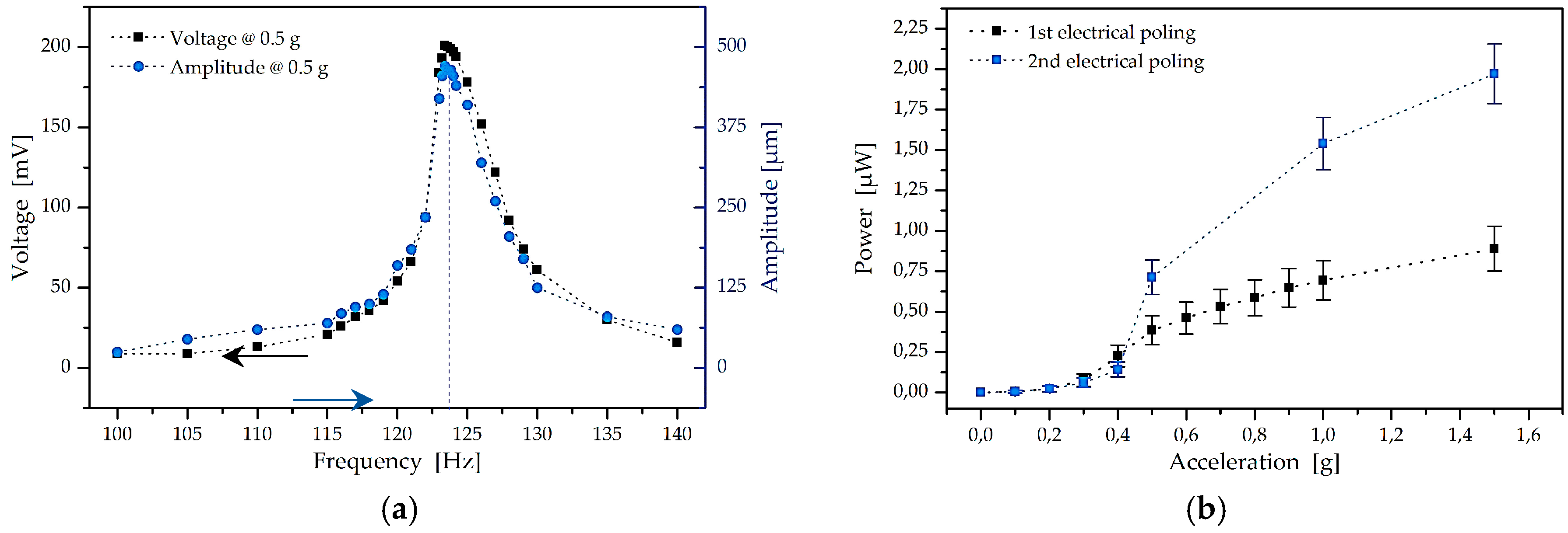
The generated peak-to-peak voltage and the harvester cantilever deflection amplitude were recorded for various vibration frequencies and accelerations. Figure 3a indicates that the cantilever resonant frequency is about 123 Hz and the maximum amplitude attained is about 500 μm for 0.5 g acceleration. The difference from the simulated values can be explained by the following facts: (1) the experimentally obtained thickness of the layers of the piezoelectric stack differed from the layer thickness used in the simulation; (2) a polymer reinforcement layer had to be added to the cantilever to prevent breakage.
4.2. Generated Voltage and Power
Figure 3b gives the power generated by subjecting the harvester to vibrations matching its resonance frequency at various accelerations. It should be stated that, in this work, a second PZT poling process with the parameters indicated in Section 3, but for a longer poling duration (5 min), was applied on the cantilever. This second PZT poling process lead to more power generated from the harvester (Figure 3b). To verify the origin of this result, the cantilever deflection was analyzed as a function of acceleration after each poling process and was found to provide comparable amplitudes, unaltered by the poling process. This confirms that the second poling process enhanced the piezoelectric properties of the PZT.
Further the generated peak-to-peak voltage and the corresponding power as a function of load resistance were determined at the harvester resonance frequency and for 0.5 g acceleration (Figure 4a). A maximum peak-to-peak voltage of about 1 V and a maximum power of about 0.7 μW were obtained in this way, the latter corresponding to an optimal load resistance of ~180 kΩ. This finding is consistent with additional measurements performed by means of impedance spectroscopy.
Figure 4b shows the generated power and the cantilever deflection amplitude obtained for various accelerations at the harvester resonant frequency. The highest power measured was about 2 μW for a cantilever deflection of about 800 μm.
The experimental results were in general agreement with the simulations results. Further optimization of chip manufacturing processes is however needed, in particular with regard to the PZT layer.
5. Conclusions
This paper presented the design, fabrication and characterization of a piezoelectric MEMS harvester of 25 × 20 × 0.475 mm3 dimensions with optimized shape able to deliver, at moderate deflection of about 800 μm, usable generated power from low frequency vibrations and low accelerations. The measured resonant frequency, maximum peak-to-peak voltage and highest power of the cantilever device were 123 Hz, 1 V and 2 μW, respectively. This design has advantages for integration with microelectronics devices.
Acknowledgments
This work was supported by the FhG internal programs under project no. 600 628. The authors would like to thank to S. Gebhardt (Fraunhofer IKTS, Dresden, Germany) for the PZT films deposition, Christian Drabe for his help with the cantilever technology and Martin Blasl, Konrad Seidel, Hans-Jürgen Holland and Mathias Landwehr for fruitful discussions.
Conflicts of Interest
The authors declare no conflict of interest.
References
- Li, H.; Tian, C.; Deng, D. Energy harvesting from low frequency applications using piezoelectric materials. Appl. Phys. Rev. 2014, 1, 041301:1–041301:20. [Google Scholar] [CrossRef]
- Kang, M.-G.; Jung, W.-S.; Kang, C.-Y.; Yoon, S.-J. Recent Progress on PZT Based Piezoelectric Energy Harvesting Technologies. Actuators 2016, 5, 1–17. [Google Scholar] [CrossRef]
- Roundy, S.; Leland, E.S.; Baker, J.; Carleton, E.; Reilly, E.; Lai, E.; Otis, B.; Rabaey, J.M.; Wright, P.K.; Sundararajan, V. Improving power output for vibration-based energy scavengers. IEEE Pervasive Comput. 2005, 47, 28–36. [Google Scholar] [CrossRef]
- Ernst, D.; Bramlage, B.; Gebhardt, S.E.; Schönecker, A.J. High performance PZT thick film actuators using in plane polarisation. Adv. Appl. Chem. 2015, 114, 237–242. [Google Scholar] [CrossRef]
- Gebhardt, S.; Schänecker, A.; Bruchmann, C. Integrated actuators based on PZT think films for microsystems applications. In Actuator 2010; Bremen, German, 2010; pp. 122–125. ISBN 978-3-933339-13-3. [Google Scholar]
Figure 1.
(a) Si/PZT cantilever harvester structure (up: top view; down: side view); (b) 3D-mode shape of the harvester structure according to (a), namely the 1st mode at 50 Hz resonance frequency.
Figure 1.
(a) Si/PZT cantilever harvester structure (up: top view; down: side view); (b) 3D-mode shape of the harvester structure according to (a), namely the 1st mode at 50 Hz resonance frequency.

Figure 2.
Fabricated harvester cantilever: (a) Cantilever structures on a silicon wafer; (b) Examples of a cantilever of 25 × 20 mm2 footprint and a cantilever chip of 18 × 20 mm2 footprint on a PCB.
Figure 2.
Fabricated harvester cantilever: (a) Cantilever structures on a silicon wafer; (b) Examples of a cantilever of 25 × 20 mm2 footprint and a cantilever chip of 18 × 20 mm2 footprint on a PCB.

Figure 3.
(a) Peak-to-peak voltage and amplitude as a function of frequency at 0.5 g acceleration for the harvester structure from Figure 1a; (b) Generated power as a function of acceleration after the 1st and the 2nd PZT poling process.
Figure 3.
(a) Peak-to-peak voltage and amplitude as a function of frequency at 0.5 g acceleration for the harvester structure from Figure 1a; (b) Generated power as a function of acceleration after the 1st and the 2nd PZT poling process.

Figure 4.
(a) Peak-to-peak voltage and generated power as a function of load resistance at the harvester resonance frequency and 0.5 g acceleration; (b) Generated power and amplitude as a function of acceleration at the resonance frequency and optimal load resistance.
Figure 4.
(a) Peak-to-peak voltage and generated power as a function of load resistance at the harvester resonance frequency and 0.5 g acceleration; (b) Generated power and amplitude as a function of acceleration at the resonance frequency and optimal load resistance.

Publisher’s Note: MDPI stays neutral with regard to jurisdictional claims in published maps and institutional affiliations. |
© 2017 by the authors. Licensee MDPI, Basel, Switzerland. This article is an open access article distributed under the terms and conditions of the Creative Commons Attribution (CC BY) license (https://creativecommons.org/licenses/by/4.0/).
Share and Cite
MDPI and ACS Style
Costache, F.; Pawlik, B.; Rieck, A. Development of a Compact, Low-Frequency Vibration, Piezoelectric MEMS Energy Harvester. Proceedings 2017, 1, 588. https://doi.org/10.3390/proceedings1040588
AMA Style
Costache F, Pawlik B, Rieck A. Development of a Compact, Low-Frequency Vibration, Piezoelectric MEMS Energy Harvester. Proceedings. 2017; 1(4):588. https://doi.org/10.3390/proceedings1040588
Chicago/Turabian StyleCostache, Florenta, Boscij Pawlik, and Andreas Rieck. 2017. "Development of a Compact, Low-Frequency Vibration, Piezoelectric MEMS Energy Harvester" Proceedings 1, no. 4: 588. https://doi.org/10.3390/proceedings1040588