RFID Integration into a Low Power Sensor Platform †


Center for Integrated Sensor Systems, Danube University Krems, 3500 Krem, Austria
*
Author to whom correspondence should be addressed.
†
Presented at the Eurosensors 2017 Conference, Paris, France, 3–6 September 2017.
Proceedings 2017, 1(4), 591; https://doi.org/10.3390/proceedings1040591
Published: 29 August 2017
(This article belongs to the Proceedings of Proceedings of Eurosensors 2017, Paris, France, 3–6 September 2017)
Abstract
:Beyond identification purposes, RFID (Radio Frequency Identification) is an elegant way to transmit wireless sensor data. There are several RFID transponder ICs on the market, but for the data read out of the sensors, a low power microcontroller (µC) with a specific functionality is also often a necessary part of the system. So we present an easy way to integrate the functionality of the RFID transponder directly into the microcontroller. This reduces costs and minimizes the PCB footprint. In particular, an implementation of an RFID tag, compatible with ISO/IEC 14443-2, Type B, into a commercial low power µC is demonstrated.
1. Introduction
The RFID system according to the ISO Standard comprises a reader (Proximity Coupling Device, PCD) and a tag with a transponder (Proximity Card, PICC). Both communicate through magnetic coupling at a carrier frequency of 13.56 MHz. A block diagram of such setup is shown in Figure 1. The RFID transponder and the microcontroller are often separated ICs on a sensor platform. We present an elegant way to integrate the functionality of the RFID transponder IC directly into the microcontroller. This conserves costs and minimizes the PCB footprint to only a few external components. In particular, an ISO/IEC 14443-2, Type B [1] compatible implementation is demonstrated.
2. Materials and Methods
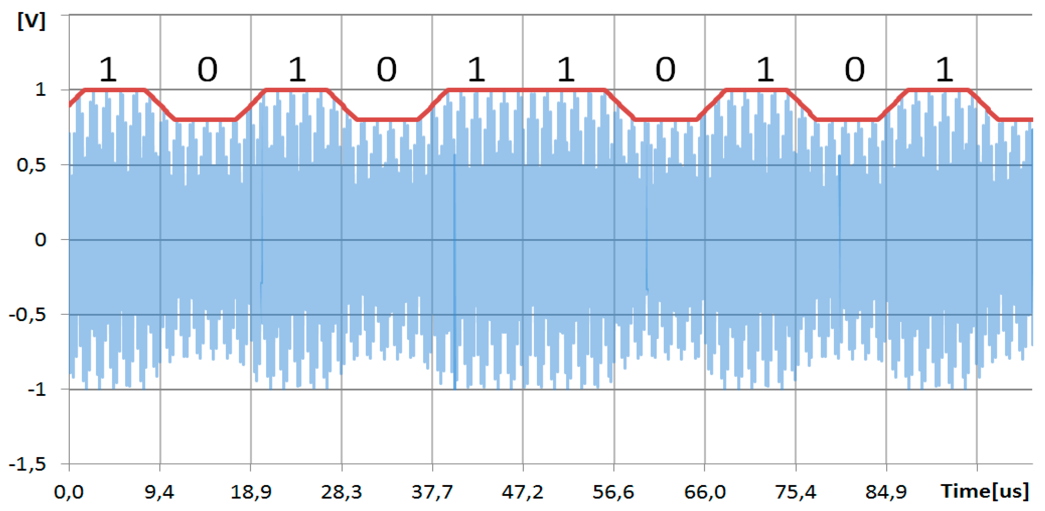
In order to resemble the transponder IC’s functionality, some further specifications of the ISO standard are discussed. During upload, the PCD sends data to the PICC by amplitude modulation (8–14%) and a data rate of 106 kBit/s as shown in Figure 2.
The PICC communicates with the PCD over an amplitude load modulated subcarrier at a frequency of 13.56 MHz/16 = 0.8475 MHz The subcarrier itself is modulated by binary phase shift keying (BPSK) with a data rate of 106 kbit/s, Figure 3.
To integrate the RFID functionality directly into a microcontroller, one of its timers, (e.g., timer 1) is used for the subcarrier modulation. Its source is the carrier signal (pin = CARRIER_SENSE). The counting frequency is 13.56 MHz/4 and its counting scheme is 0, 1, 2, 3, 0.... This is shown in Figure 4. By using the timer-compare function, the modulation pin can be toggled (pin = SUBCARRIER_MODULATION) at count 2. At a timer overflow, the pin SUBCARRIER_MODULATION is set or reset, depending on the data to be transmitted. A second timer (e.g., Timer 2) runs at the same source frequency and the timer overflow is synchronized with the data transmission rate of 106 kHz (13.56 MHz/128). The overflow flag is polled by software, which modifies the “set or reset” property of the first timer according to the transmitted bit stream. The polling is done in an unrolled loop for timing issues.
In Figure 5, a schematic of the integrated RFID transponder is shown. The diode (D1) demodulates, on the one hand, the AM uplink signal (Figure 2), and on the other hand, in combination with D2, rectifies the carrier to generate the supply voltage (VCC). The generation of the supply voltage may be omitted if the device is self-powered. The NPN transistor acts as a sensitive amplifier for the AM uplink signal, which is forwarded to the microcontroller serial input (UART_RX).
In many cases, microcontrollers have internal pullup and pulldown resistors. They can be used to replace R1, R3 and R4, which further reduces PCB footprint.
3. Results and Discussion
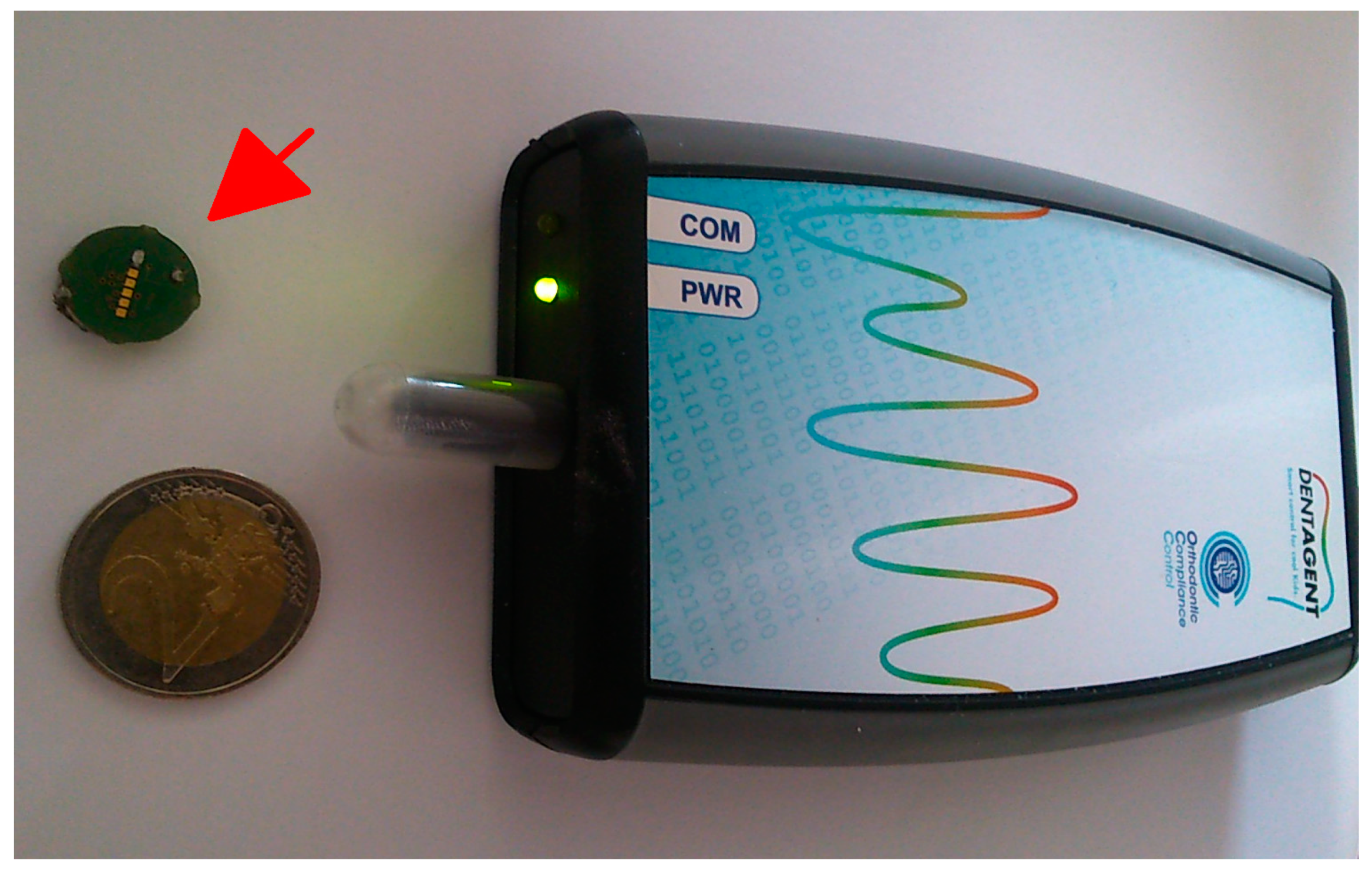
The concept was successfully implemented and tested on several low power microcontrollers (MSP430F149, MSP430F2370, MSP430FR5739, Texas Instruments, TX, USA). Because of the slow system clock (8 MHz RC-Oscillator), which is common at low power systems, it was necessary to use assembler coding and optimization techniques like loop unrolling. The integrated RFID transponder works properly with a commercial wireless readable miniature temperature logger [2,3], Figure 6. In this setup, reading distances of about 2 cm are achieved, which is sufficient for this specific application. This limitation is mainly caused by the relatively small antenna size. Due to the relatively low hardware requirements, (2 timer units), it should be possible to transfer the setup to other microcontrollers easily.
Acknowledgments
The project was founded by the Austrian Research Promotion Agency (FFG) under the IDs #850265 and #855567.
Conflicts of Interest
The authors declare no conflict of interest.
References
- Baddeley, D. Motorola. Radio frequency power and signal interface. ISO/IEC FCD 14443-2, 1999. [Google Scholar]
- OCC Orthodontic Compliance Controll GmbH. Available online: www.dentagent.com (accessed on 4 May 2017).
- Brandl, M.; Grabner, J.; Kellner, K.; Seifert, F.; Nicolics, J.; Grabner, S.; Grabner, G. A low-cost wireless sensor system and its application in dental retainers. IEEE Sens. J. 2009, 9, 255–262. [Google Scholar] [CrossRef]
Figure 1.
Block diagram of a RFID sensor system. The RFID transponder IC can be replaced by direct integration into the microcontroller.
Figure 1.
Block diagram of a RFID sensor system. The RFID transponder IC can be replaced by direct integration into the microcontroller.
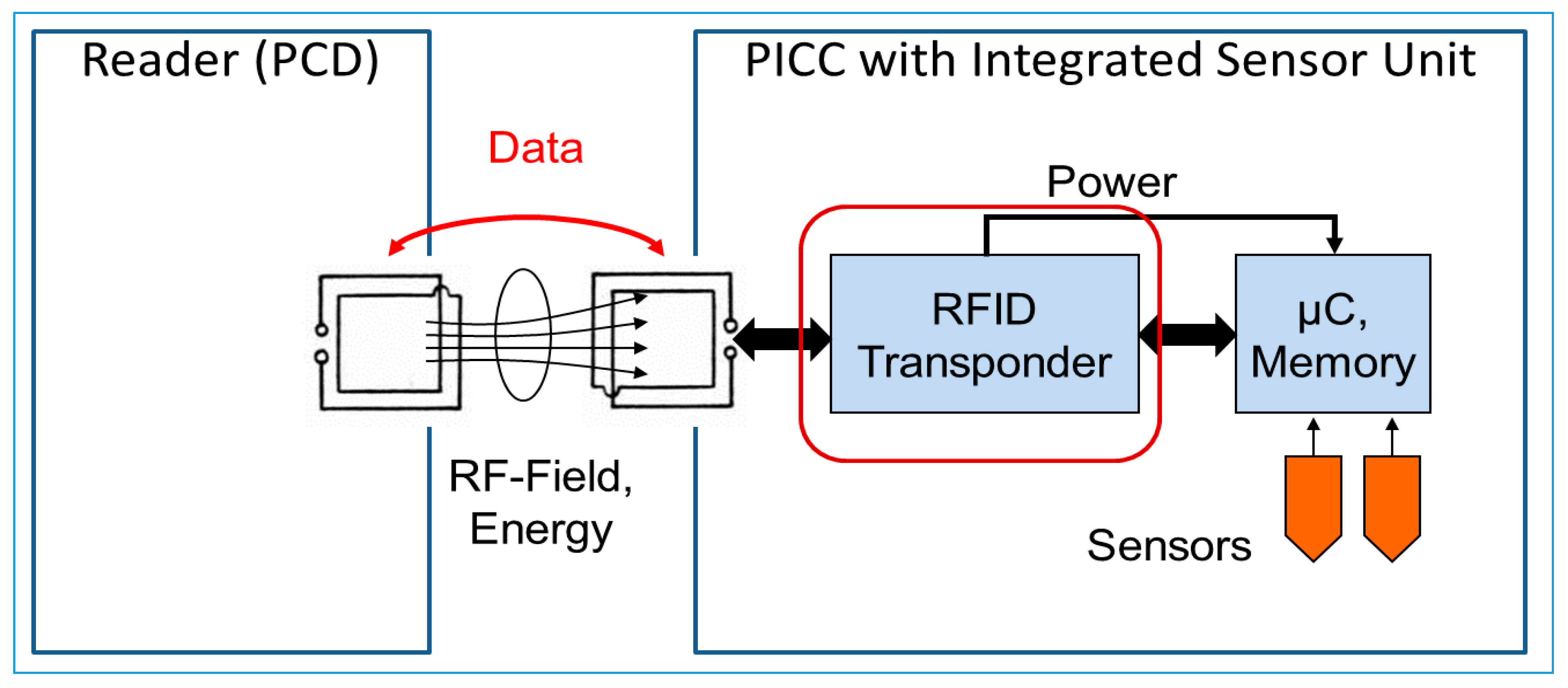
Figure 2.
Oscillogram of PID to PICC communication via ~10% amplitude modulation. Logic Zero is represented by low amplitude, logic one is by high amplitude of the carrier (13.56 MHz).
Figure 2.
Oscillogram of PID to PICC communication via ~10% amplitude modulation. Logic Zero is represented by low amplitude, logic one is by high amplitude of the carrier (13.56 MHz).

Figure 3.
Principle of the BPSK modulation scheme. The load modulated subcarrier (0.8475 MHz) is 180° phase shifted according to the bitstream for PICC to PID communication.
Figure 3.
Principle of the BPSK modulation scheme. The load modulated subcarrier (0.8475 MHz) is 180° phase shifted according to the bitstream for PICC to PID communication.
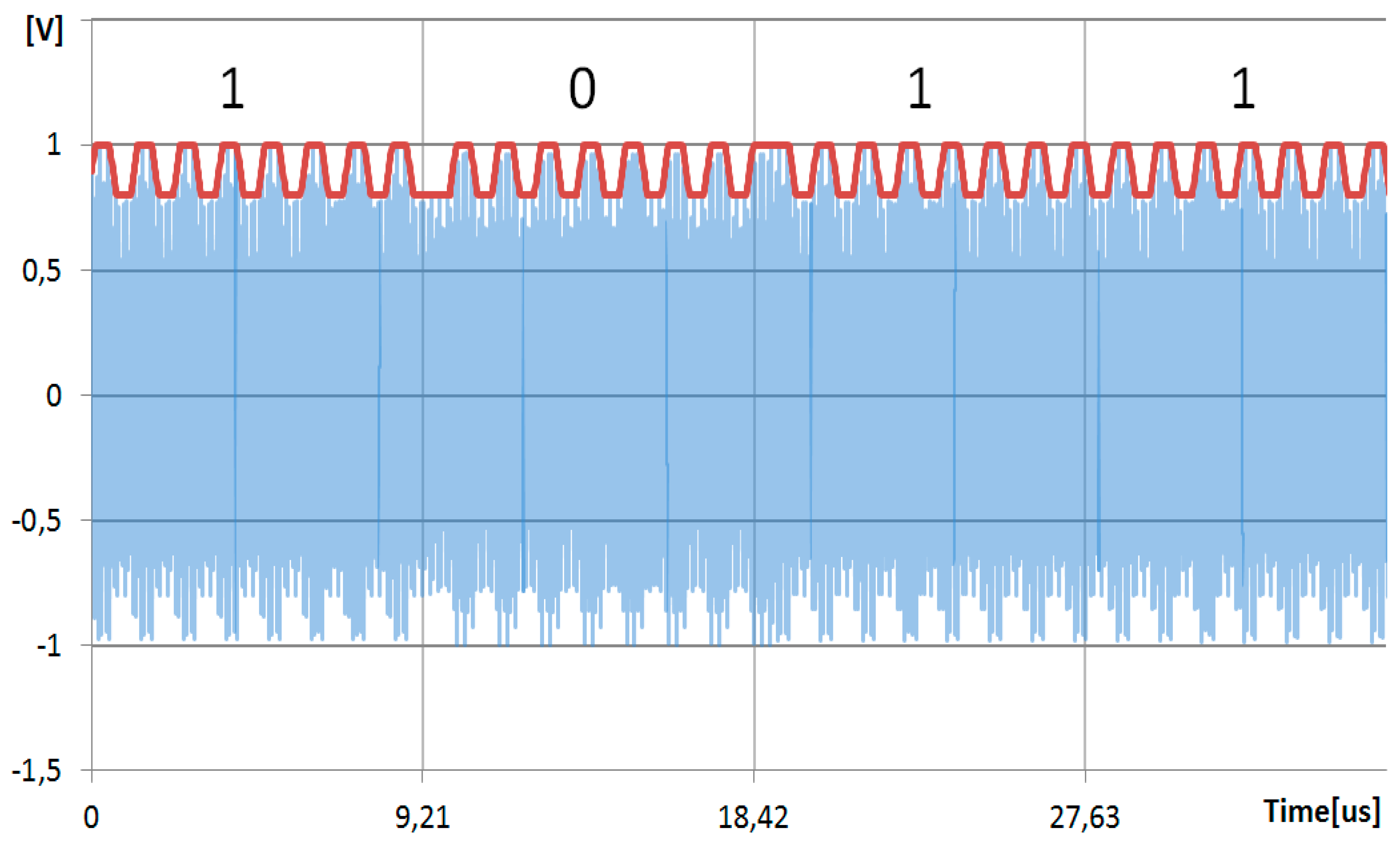
Figure 4.
Timer counting scheme: SUBCARRIER_MODULATION is toggled by timer 1. On timer 2 overflow, the toggling scheme is inverted or not, depending on the data to be transmitted. This generates the BPSK signal.
Figure 4.
Timer counting scheme: SUBCARRIER_MODULATION is toggled by timer 1. On timer 2 overflow, the toggling scheme is inverted or not, depending on the data to be transmitted. This generates the BPSK signal.
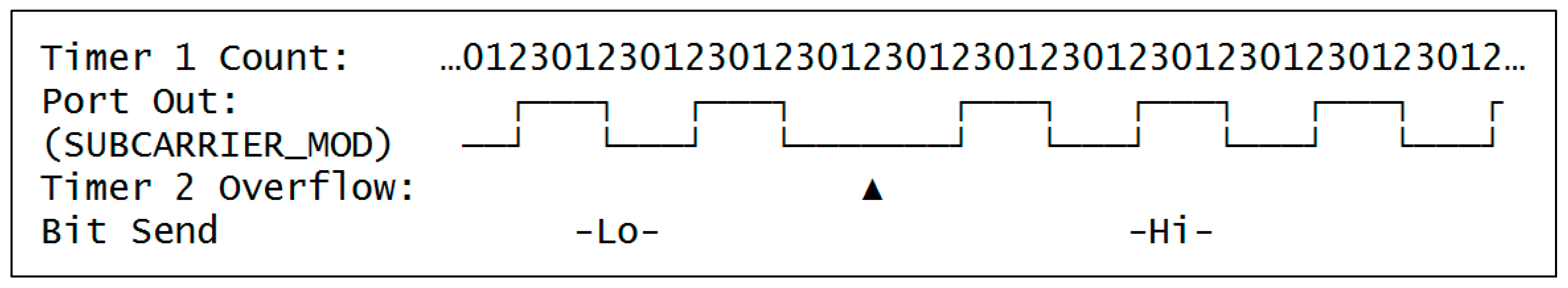
Figure 5.
Schematic of the integrated RFID transponder. Only a few components are needed: Microcontroller, resonant antenna, a feed of the carrier into the microcontroller (C_CS), load modulator (R2), AM demodulator (D1), transistor amplifier, and supply voltage generator (D2).
Figure 5.
Schematic of the integrated RFID transponder. Only a few components are needed: Microcontroller, resonant antenna, a feed of the carrier into the microcontroller (C_CS), load modulator (R2), AM demodulator (D1), transistor amplifier, and supply voltage generator (D2).
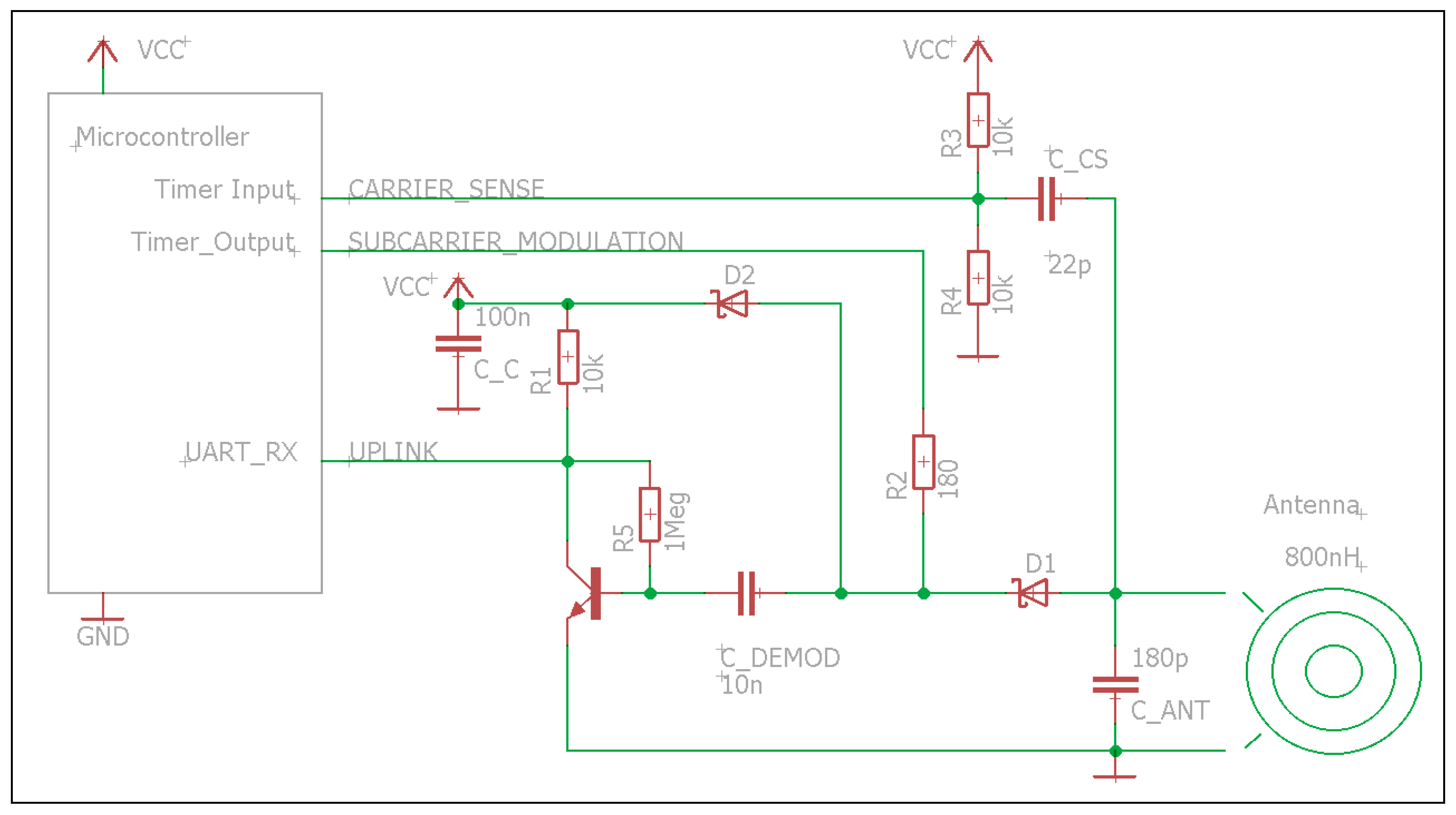
Figure 6.
Picture of the commercial temperature logger system. The arrow points to the RFID readable temperature logger. The RFID reader station with USB connection to a PC is shown on the right.
Figure 6.
Picture of the commercial temperature logger system. The arrow points to the RFID readable temperature logger. The RFID reader station with USB connection to a PC is shown on the right.

Publisher’s Note: MDPI stays neutral with regard to jurisdictional claims in published maps and institutional affiliations. |
© 2017 by the authors. Licensee MDPI, Basel, Switzerland. This article is an open access article distributed under the terms and conditions of the Creative Commons Attribution (CC BY) license (https://creativecommons.org/licenses/by/4.0/).
Share and Cite
MDPI and ACS Style
Kellner, K.; Brandl, M. RFID Integration into a Low Power Sensor Platform. Proceedings 2017, 1, 591. https://doi.org/10.3390/proceedings1040591
AMA Style
Kellner K, Brandl M. RFID Integration into a Low Power Sensor Platform. Proceedings. 2017; 1(4):591. https://doi.org/10.3390/proceedings1040591
Chicago/Turabian StyleKellner, Karlheinz, and Martin Brandl. 2017. "RFID Integration into a Low Power Sensor Platform" Proceedings 1, no. 4: 591. https://doi.org/10.3390/proceedings1040591