Integrated Sensor System for Condition Monitoring of Electromechanical Cylinders †


1
ZeMA—Centre for Mechatronics and Automation gGmbH, Saarbrücken, Germany
2
Lab for Measurement Technology, Saarland University, Saarbrücken, Germany
3
University of Applied Sciences, Saarbrücken, Germany
*
Author to whom correspondence should be addressed.
†
Presented at the Eurosensors 2017 Conference, Paris, France, 3–6 September 2017.
Proceedings 2017, 1(4), 626; https://doi.org/10.3390/proceedings1040626
Published: 9 August 2017
(This article belongs to the Proceedings of Proceedings of Eurosensors 2017, Paris, France, 3–6 September 2017)
Abstract
:In this work, a sensor system mechanically integrated in an electromechanical cylinder is presented with the goal of measuring relevant quantities for condition monitoring. The system monitors those parts of the cylinder which are mainly affected by wear processes, i.e., spindle drive and ball bearings. Primarily low-cost MEMS sensors, e.g., for acceleration/vibration, IR emission, and position, are integrated on specially designed ring PCBs which are mounted at the front of the spindle ball screw nut allowing, e.g., the detection of spindle defects.
1. Introduction
Besides their classical applications in assembly and handling systems, electromechanical cylinders (EMCs) are increasingly applied as feed drive in machine tools, due to their unique combination of high loads, precision, and flexibility. Although EMCs are considered to be highly reliable, they nevertheless contribute with the largest share of machine tool failure causes, approx. 38% [1]. Especially the spindle drive and ball system were assessed to be the critical components suffering from wear due to internal damaging processes such as abrasion and strong alternating loads [2]. Therewith, the spindle drive is a highly promising measuring point for condition monitoring of EMCs.
2. Concept and Evaluation
The sensor system is designed as prototype, containing a wide range of (partially redundant) sensors and measurands (Table 1) that will be individually evaluated and compared in laboratory tests in order to significantly simplify the system for future practical application. Actually, it consists of two separate subsystems: First, two stacked sensor PCBs (Figure 1b) are mounted on the front surface of the ball screw inside the cylinder housing (Festo ESBF-BS-63-400-5P, ⌀ 63 mm, 400 mm stroke, 5 mm pitch, 7 kN max. force) containing in total 9 MEMS sensors as described in Table 1.
Therewith, the PCBs are linearly traversing coupled with the spindle nut with a ribbon cable led out through the rotation lock groove to the external data acquisition unit.
Furthermore, the rotary position of the spindle shaft is measured by an AMR Wheatstone bridge sensor [3] with external bias magnet provided by our project partner Sensitec generating the support field which interacts with ferromagnetic thread teeth. The sensor itself is positioned fixed at the cylinder housing close to the ball bearing (cf. Figure 1a) pointing to the thread with a working distance of 1 mm. During rotation, the relative position of sensor and tooth changes periodically resulting in sine and cosine sensor signals (Figure 2a). Using arctangent function a saw tooth signal can be used to linearly map the translation of spindle nut. The measurement error was estimated to be less than 100 μm (Figure 2a) assuming an ideally constant movement. Figure 2b shows the derived velocity signal and the integrated position of the spindle nut (requires zeroing at the beginning) with a position error of approx. 1.7 mm after six strokes (0.68% error). Thus, the actual rotational speed can be measured which allows to adapt the feature extraction based on this information e.g., detecting amplitudes of characteristic vibration frequencies that vary with velocity as shown in the following.
For the first evaluation, we focus on vibration monitoring using the FXLN accelerometer; data acquisition is externally performed using a NI USB 6343 (fs 20 kHz, res. 16 bit). The EMC is driven with defined velocities and without external load. As Figure 3 indicates, characteristic frequencies can be observed in the amplitude spectrum, that are, in particular, the fundamental mechanical frequency and its first harmonics. As described by Crocker [4], especially (1) is an indicator for imbalance whereas anomalies of (2) point to misalignment. Besides, rollover frequencies of ball bearing, outer (4) and inner (5) ring, and spindle (9) are visible as well as rotating field (5) and rotating field multiplied by the number of pole pairs (10) of the servo motor (Festo EMMS-AS). In addition, const. amplitude curvatures above 500 Hz suggest structural resonances of the housing. The peak acceleration in radial direction was measured to be up to ±3 g.
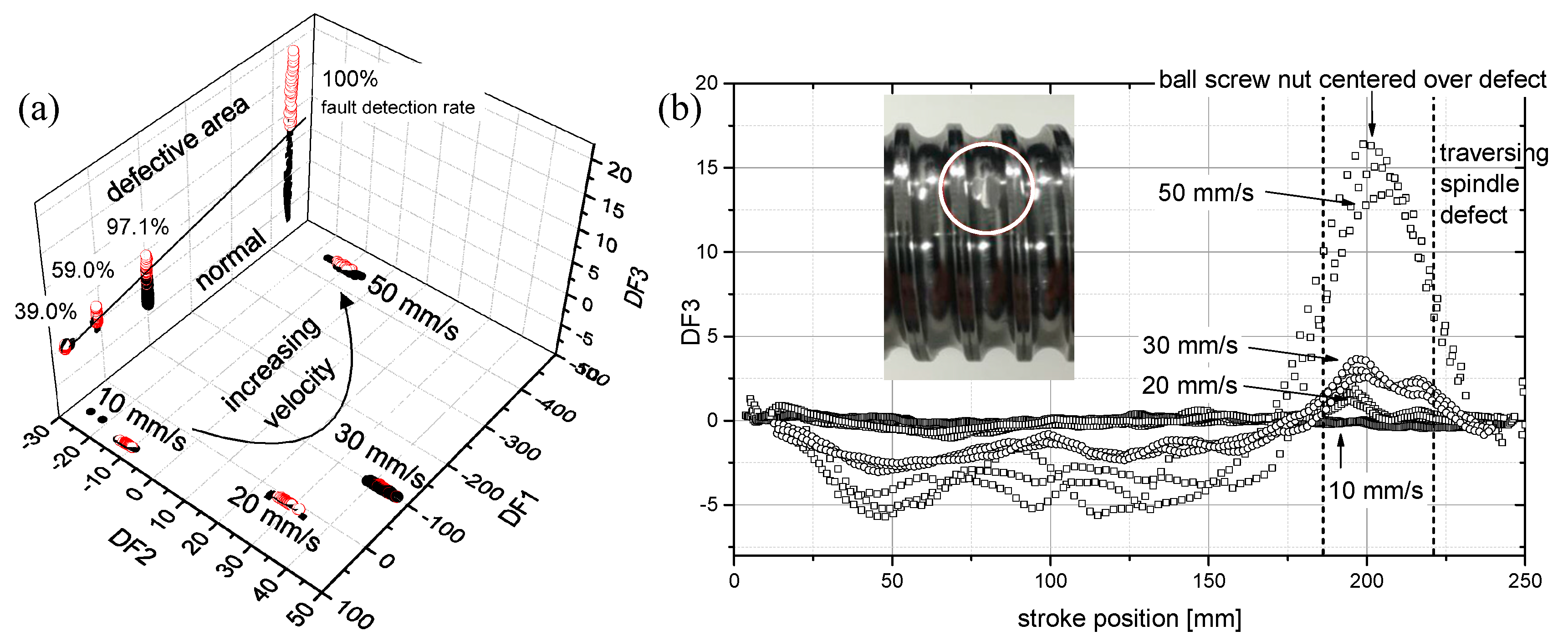
To evaluate the sensor system in a condition monitoring scenario, we induced a local abrasion of the spindle at stroke position 185 mm and recorded several stroke movements with varying velocity and three repetitions. For signal processing, short-time Fourier transform (STFT) was applied (length 10,000/overlap 2000 samples) with subsequent feature extraction and selection as previously demonstrated [5]. Feature extraction captures in total of 210 statistical parameters such as median, variance, skewness, and kurtosis in different intervals of the amplitude spectra of three acceleration axes (FXLN sensor). The features are selected by F-value ranking of univariate ANOVA and dimensionally reduced to three discriminant functions (DFs) using Linear Discriminant Analysis (LDA). With this approach the maximum class separation can be obtained. The latter algorithms are supervised learning methods, i.e., require class-annotated data which were given as velocity information and local spindle condition traversed by the spindle nut. Figure 4a shows the resulting 3D-projection of sensor data with the planes DF1-DF2 and DF1-DF3 separating the different velocity levels and spindle conditions, respectively. Here, 10, 20, and 50 mm/s velocity classes were used for training and 30 mm/s velocity was used for evaluation. It can be seen that the intermediate velocity class fits the data-based model and that the fault identification rate improves with increasing velocity. Figure 4b shows the plot of DF3 over stroke position clearly indicating the defect. The maximum is blurred, first, due to the interaction of balls and spindle defect over a distance of 30 mm and, second, also results from the STFT temporal blur. Furthermore, especially at low speeds with accordingly higher local resolution, two local maxima can be seen indicating the entry and exit points of the spindle nut passing over the defect.
3. Conclusion and Outlook
Based on low-cost MEMS sensors, the multi-parameter sensor system captures relevant measurement quantities for the condition assessment of EMCs including multi-axes acceleration, sound and IR emission, as well as temperature and rotary/linear position. With the latter, it could be shown, that rotational speed can be measured as relevant parameter for feature extraction, i.e., obtaining characteristic vibration frequencies combining all required quantities for an integrated stand-alone condition monitoring system. Furthermore, the stroke position dependent analysis of signals can be used for fault analysis and diagnosis differentiating between globally superimposed disturbances and local anomalies such as defects of the spindle. In future, we plan to miniaturize the system to enhance the usable travel distance of the cylinder, and, second, to investigate the feasibility for residual lifetime prognosis during long-term tests of cylinder in combination with multivariate statistical analysis taking all available sensors into account.
Acknowledgments
We would like to thank Jörg Traute from Sensitec GmbH (Lahnau, Germany) for technical support and valuable discussions and gratefully acknowledge the funding of the German research ministry BMBF in the programme SElekt I4.0, project MoSeS-Pro, funding code 16ES0419K.
Conflicts of Interest
The authors declare no conflict of interest.
References
- Maier, D. Sensorlose online Zustandserfassung von Vorschubantriebskomponenten in Werkzeugmaschinen. Berichte aus dem Institut für Maschinenelemente, Report nr. 157. Ph.D. Thesis, University of Stuttgart, Stuttgart, Germany, 2014. ISBN: 978-3-936100-58-7. [Google Scholar]
- Forstmann, J. Kugelgewindetriebe im Einsatz an Kunststoffspritzgießmaschinen—Lebensdauerprognose und Optimierung. Ph.D. Thesis, University of Duisburg-Essen, Duisburg, Germany, 2010. [Google Scholar]
- Doms, M.; Slatter, R. Magnetoresistive sensors for angle, position, and electrical current measurement in demanding environments. Proc. SPIE 2014, 9113. [Google Scholar] [CrossRef]
- Crocker, M. Handbook of Acoustics; John Wiley & Sons: Hoboken, NJ, USA, 1998; pp. 701–712. [Google Scholar]
- Helwig, N.; Klein, S.; Schütze, A. Identification and quantification of hydraulic system faults based on multivariate statistics using spectral vibration features. Proc. Eng. 2015, 120, 1225–1228. [Google Scholar] [CrossRef]
Figure 1.
(a) Mechanical integration of the sensor system inside the EMC and (b) realization of the stacked sensor ring PCBs with spindle shaft inside in a disassembled cylinder.
Figure 1.
(a) Mechanical integration of the sensor system inside the EMC and (b) realization of the stacked sensor ring PCBs with spindle shaft inside in a disassembled cylinder.
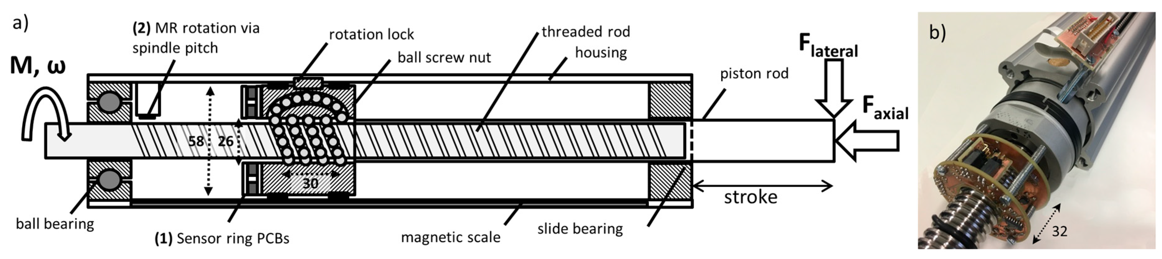
Figure 2.
(a) Excerpt of sine and cosine signals of spindle teeth measurement, derived arctangent signal and position error during constant velocity phase (20 mm/s); (b) speed measurement and absolute position integrated during positioning with six velocity levels (10, 20, 30, 50, 75, 100 mm/s).
Figure 2.
(a) Excerpt of sine and cosine signals of spindle teeth measurement, derived arctangent signal and position error during constant velocity phase (20 mm/s); (b) speed measurement and absolute position integrated during positioning with six velocity levels (10, 20, 30, 50, 75, 100 mm/s).
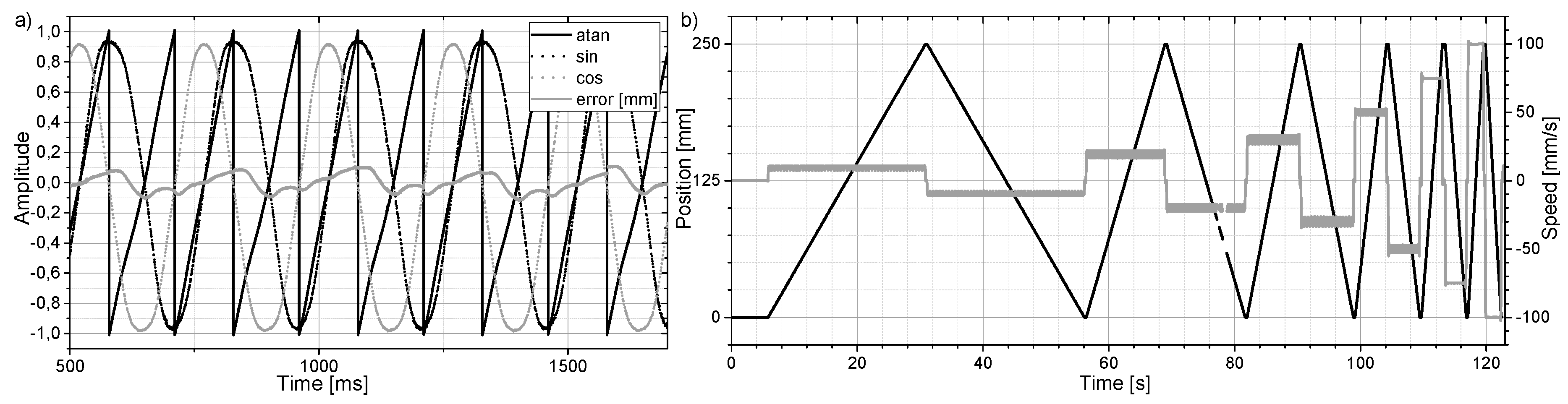
Figure 3.
Amplitude spectra of FXLN accelerometer in radial (y-axis) direction with varying rotation speed from 10 (~50 mm/s) to 20 Hz (~100 mm/s).
Figure 3.
Amplitude spectra of FXLN accelerometer in radial (y-axis) direction with varying rotation speed from 10 (~50 mm/s) to 20 Hz (~100 mm/s).

Figure 4.
(a) LDA projection of 30 selected vibration features, n = 2883; classification rate determined with 10-fold CV for Mahalanobis distance classifier; (b) deliberate abrasion as local defect of the spindle and corresponding signal of DF3 vs. stroke position (moving average over 10 data points).

Table 1.
Sensors used in integrated sensor system.
| Measurand | Location | Description | Sensor Type | Sensitivity; Bandwidth |
|---|---|---|---|---|
| Linear stroke encoder (magnetoresistive) | PCB on ball screw nut (1); magnetic scale in groove of spindle housing | Sensitec: GLM 715 | GMR Wheatstone bridges (sin/cos) with 1.57 mm pole pitch | 9 mV/V; 1 MHz |
| Rotary encoder (magnetoresistive) | Housing of spindle drive (2); scale: thread structure | AL780 with bias magnet | AMR Wheatstone bridges (sin/cos) with 5 mm pole pitch | 11 mV/V; 1 MHz |
| Acceleration/vibration | PCB on ball screw nut (1) | Analog Devices: ADXL001 | Capac. MEMS—1 axis | 16 mV/g; 22 kHz |
| ADXL335 | Capac. MEMS—3 axes | 300 mV/g; 550–1600 Hz | ||
| Freescale FXLN8371QR1 | Capac. MEMS—3 axes | 57–229 mV/g; 600–2700 Hz | ||
| Sound emission | Knowles: SPH0642HT5H-1 | MEMS microphone | −38 dBV/Pa; 10–10,000 Hz | |
| SPH0641LU4H-1 | MEMS microphone | −26 dB FS; 10–80,000 Hz | ||
| IR emission | Micro-Hybrid TS1x80BA | 1-ch thermopile det. | 295 V/W DC; 25 Hz | |
| IR emission | Micro-Hybrid PS1x3C10 | 1-ch pyroel. det. | 2 kV/W AC; 16 Hz | |
| Temperature | Microchip TC1047 | Integrated thermistor | 10 m V/°C; ~1 Hz |
Publisher’s Note: MDPI stays neutral with regard to jurisdictional claims in published maps and institutional affiliations. |
© 2017 by the authors. Licensee MDPI, Basel, Switzerland. This article is an open access article distributed under the terms and conditions of the Creative Commons Attribution (CC BY) license (https://creativecommons.org/licenses/by/4.0/).
Share and Cite
MDPI and ACS Style
Helwig, N.; Merten, P.; Schneider, T.; Schütze, A. Integrated Sensor System for Condition Monitoring of Electromechanical Cylinders. Proceedings 2017, 1, 626. https://doi.org/10.3390/proceedings1040626
AMA Style
Helwig N, Merten P, Schneider T, Schütze A. Integrated Sensor System for Condition Monitoring of Electromechanical Cylinders. Proceedings. 2017; 1(4):626. https://doi.org/10.3390/proceedings1040626
Chicago/Turabian StyleHelwig, Nikolai, Philip Merten, Tizian Schneider, and Andreas Schütze. 2017. "Integrated Sensor System for Condition Monitoring of Electromechanical Cylinders" Proceedings 1, no. 4: 626. https://doi.org/10.3390/proceedings1040626