How to Improve the Performance Prediction of a Pump as Turbine by Considering the Slip Phenomenon †

 , , ,
, , ,
Abstract
:1. Introduction
2. Numerical Methods
Numerical Domain and Boundary Conditions
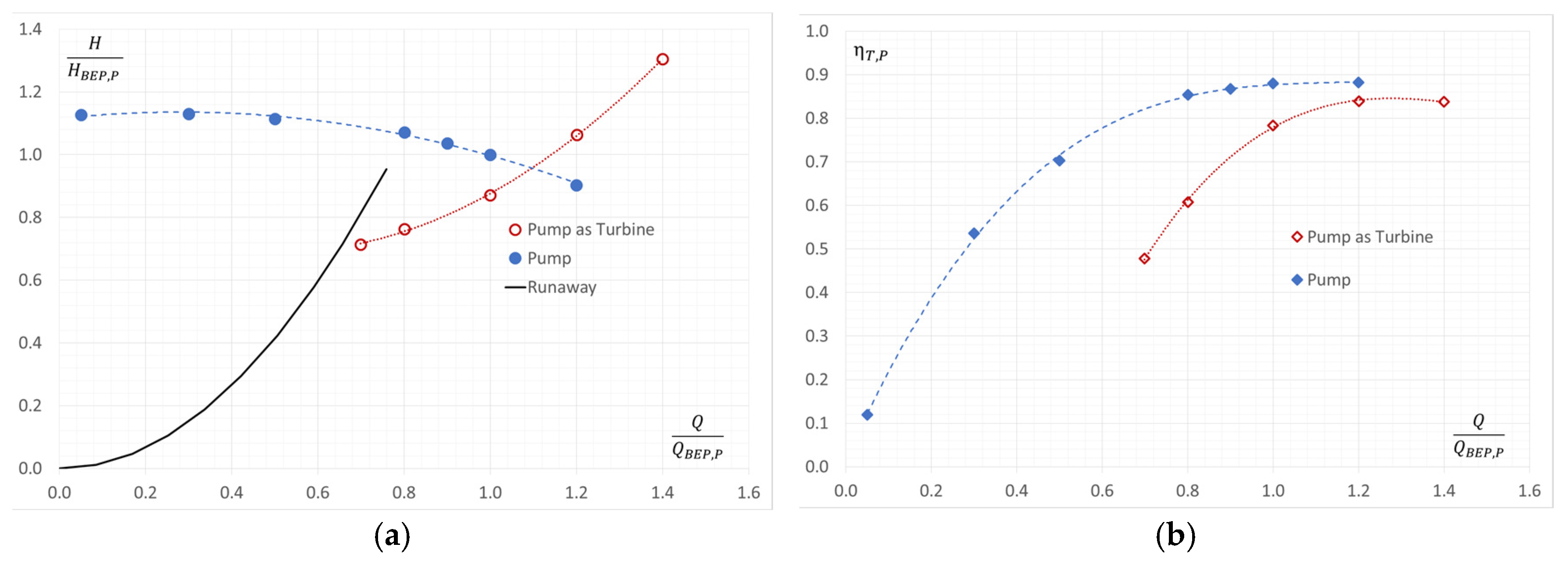
3. Evaluation of the Machine Performance
3.1. Pump Mode
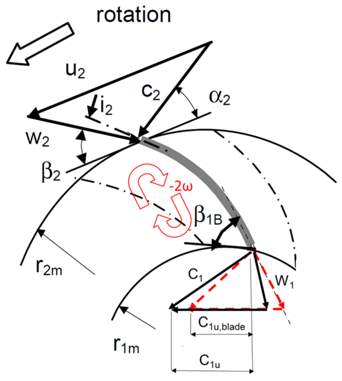
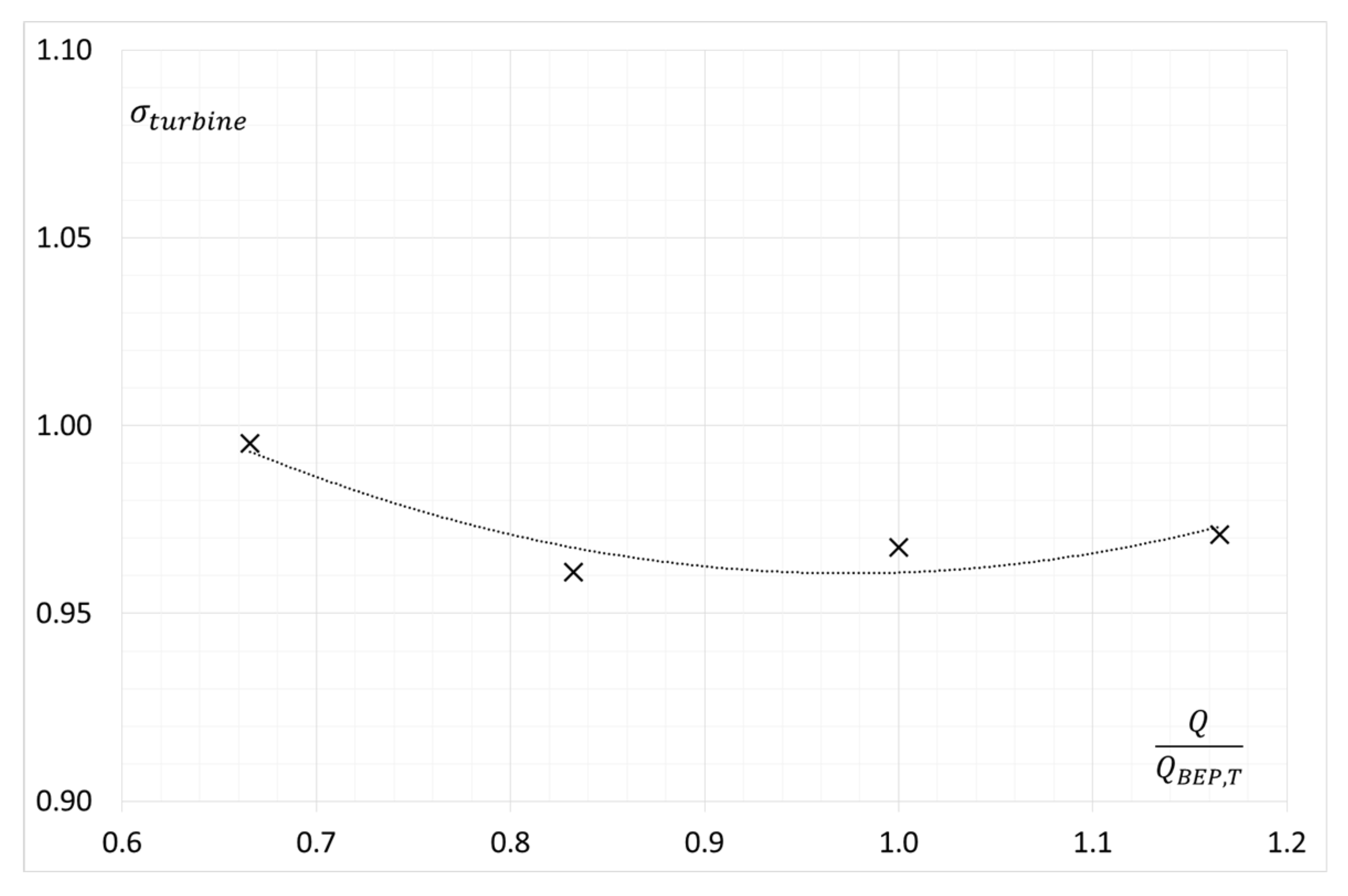
3.2. Turbine Mode
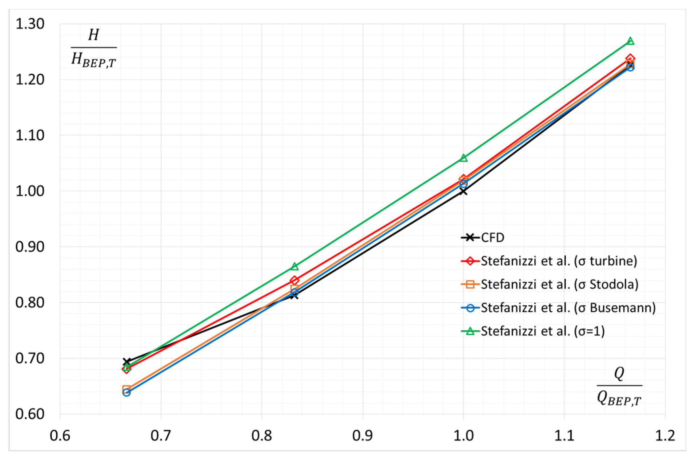
4. Results and Discussion
5. Conclusions
Author Contributions
References
- Binama, M.; Su, W.-T.; Li, X.-B.; Li, F.-C.; Wei, X.-Z.; An, S. Investigation on pump as turbine (PAT) technical aspects for micro hydropower schemes: A state-of-the-art review. Renew. Sustain. Energy Rev. 2017, 79, 148–179. [Google Scholar] [CrossRef]
- Yang, S.S.; Derakhshan, S.; Kong, F.Y. Theoretical, numerical and experimental prediction of pump as turbine performance. Renew. Energy 2012, 48, 507–513. [Google Scholar] [CrossRef]
- Derakhshan, S.; Nourbakhsh, A. Experimental study of characteristic curves of centrifugal pumps working as turbines in different specific speeds. Exp. Therm. Fluid Sci. 2008, 32, 800–807. [Google Scholar] [CrossRef]
- Barbarelli, S.; Amelio, M.; Florio, G. Predictive model estimating the performances of centrifugal pumps used as turbines. Energy 2016, 107, 103–121. [Google Scholar] [CrossRef]
- Ventrone, G. Deviazione Della Corrente Relativa Nelle Giranti Delle Turbine Francis; L’Energia Elettrica; 1972. [Google Scholar]
- Shi, G.; Liu, X.; Yang, J.; Miao, S.; Li, J. Theoretical research of hydraulic turbine performance based on slip factor within centripetal impeller. Adv. Mech. Eng. 2015, 7. [Google Scholar] [CrossRef]
- Gülich. J.F. Centrifugal Pumps, 2nd ed.; Springer: Berlin, Germany, 2008. [Google Scholar]
- Busemann, A. Das Forderhohenverhaltnis Radialer Kreiselpumpen mit Logarithmisch-Spiraligen Schaufeln. Z. Angew. Math. Mech. 1928, 8, 372–384. [Google Scholar] [CrossRef]
- Stodola, A. Dampf und Gas-Turbinen; Springer: Berlin, Germany, 1924. [Google Scholar]
- Menter, F.R.; Kuntz, M.; Langtry, R. Ten Years of Industrial Experience with the SST Turbulence Model. Turbul. Heat Mass Transf. 2003, 4, 625–632. [Google Scholar]
- Huang, P.; Bardina, J.; Coakley, T. Turbulence Modeling Validation, Testing, and Development; NASA Technical Memorandum 110446; National Aeronautics and Space Administratio (NASA): Washington, DC, USA, 1997. [Google Scholar]
- Adams, T.; Grant, C.; Watson, H. A Simple Algorithm to Relate Measured Surface Roughness to Equivalent Sand-grain Roughness. Int. J. Mech. Eng. Mechatron. 2012, 1, 66–71. [Google Scholar] [CrossRef]
- Nilsson, H. Nilsson Evaluation of OpenFOAM for CFD of turbulent flow in water turbines. In Proceedings of the 23rd IAHR Symposium, Yokohama, Japan, 17–21 October 2006. [Google Scholar]
- Stefanizzi, M.; Capurso, T.; Torresi, M.; Pascazio, G.; Ranaldo, S.; Camporeale, S.M.; Fortunato, B.; Monteriso, R. Development of a 1-D prediction model of a PaT performance under design and off-design conditions. In Proceedings of the 3rd EWaS International Conference, Lefkada, Greece, 27–30 June 2018. [Google Scholar]
- Stefanizzi, M.; Torresi, M.; Fortunato, B.; Camporeale, S.C. Experimental investigation and performance prediction modeling of a single stage centrifugal pump operating as turbine. Energy Procedia 2017, 126, 589–596. [Google Scholar] [CrossRef]


| Coarse | Medium | Fine | |
|---|---|---|---|
| Impeller (106) | 3 | 6 | 10 |
| Suction (106) | 1 | 2 | 4 |
| Discharge (106) | 2 | 3 | 6 |
| Total (106) | 6 | 11 | 20 |
| Head at BEP (m) | 139.8 | 140.8 | 141.0 |
| Time (h) 128 cores | 7 | 18 | 40 |
Publisher’s Note: MDPI stays neutral with regard to jurisdictional claims in published maps and institutional affiliations. |
© 2018 by the authors. Licensee MDPI, Basel, Switzerland. This article is an open access article distributed under the terms and conditions of the Creative Commons Attribution (CC BY) license (https://creativecommons.org/licenses/by/4.0/).
Share and Cite
Capurso, T.; Stefanizzi, M.; Torresi, M.; Pascazio, G.; Caramia, G.; Camporeale, S.M.; Fortunato, B.; Bergamini, L. How to Improve the Performance Prediction of a Pump as Turbine by Considering the Slip Phenomenon. Proceedings 2018, 2, 683. https://doi.org/10.3390/proceedings2110683
Capurso T, Stefanizzi M, Torresi M, Pascazio G, Caramia G, Camporeale SM, Fortunato B, Bergamini L. How to Improve the Performance Prediction of a Pump as Turbine by Considering the Slip Phenomenon. Proceedings. 2018; 2(11):683. https://doi.org/10.3390/proceedings2110683
Chicago/Turabian StyleCapurso, Tommaso, Michele Stefanizzi, Marco Torresi, Giuseppe Pascazio, Giovanni Caramia, Sergio M. Camporeale, Bernardo Fortunato, and Lorenzo Bergamini. 2018. "How to Improve the Performance Prediction of a Pump as Turbine by Considering the Slip Phenomenon" Proceedings 2, no. 11: 683. https://doi.org/10.3390/proceedings2110683