RFID Timing Antenna for Open Water Swimming Competitions †


Department of Network & Communication Engineering, Carinthia University of Applied Sciences Klagenfurt, 9020 Klagenfurt am Wörthersee, Austria
†
Presented at the 12th Conference of the International Sports Engineering Association, Brisbane, Queensland, Australia, 26–29 March 2018.
Proceedings 2018, 2(6), 300; https://doi.org/10.3390/proceedings2060300
Published: 15 March 2018
(This article belongs to the Proceedings of The 12th Conference of the International Sports Engineering Association)
Abstract
:RFID timing is the common method for processing results in mass sport events. Typically, it is used in running, cycling and triathlon events, but with some modifications even swimming athletes in water can be detected. In open water swimming competitions, the distance between the athletes and the RFID antenna must be larger so that escort boats or small ships can pass the gate without getting into dangerous situations. In this paper a design of an underwater RFID antenna is presented which was used during swimming events, It could span a distance up to 12 m width inside a swimming channel or offshore. The whole construction was completely immerged under the water line. The electronic components were housed in some meter distance on the beach, in a boat or in a buoy. With a reading range up to 1.5 m distance a detection rate between 94.6% and 100% could be achieved.
1. Introduction
1.1. Motivation
In mass running events, the timing systems operate with radio frequency identification (RFID) devices [1]. These devices are transponders, tags or just chips, and are fixed on the shoelace or are worn with a strap around the ankle. Depending on the athletes speed different RFID technologies with different frequencies and with different power supply (active and passive) are available. All these transponders can be detected by an RFID decoder and a detection line formed by a detection loop or antenna on or in the floor. Usual distances between transponders and detection loop range up to 1.5 m. Detecting two or more runners passing the reading area at the same time is possible. The decoder registers all transponders crossing the detection line and stores a tuple of tag ID and timestamp for each passing. Usually, timing stations are situated not only at the finish line but also at turning points to document the split times. For live timing these split times can also be used for informing the sport moderator, who can report the current ranking directly to the audience and pre-announce the next athletes to pass.
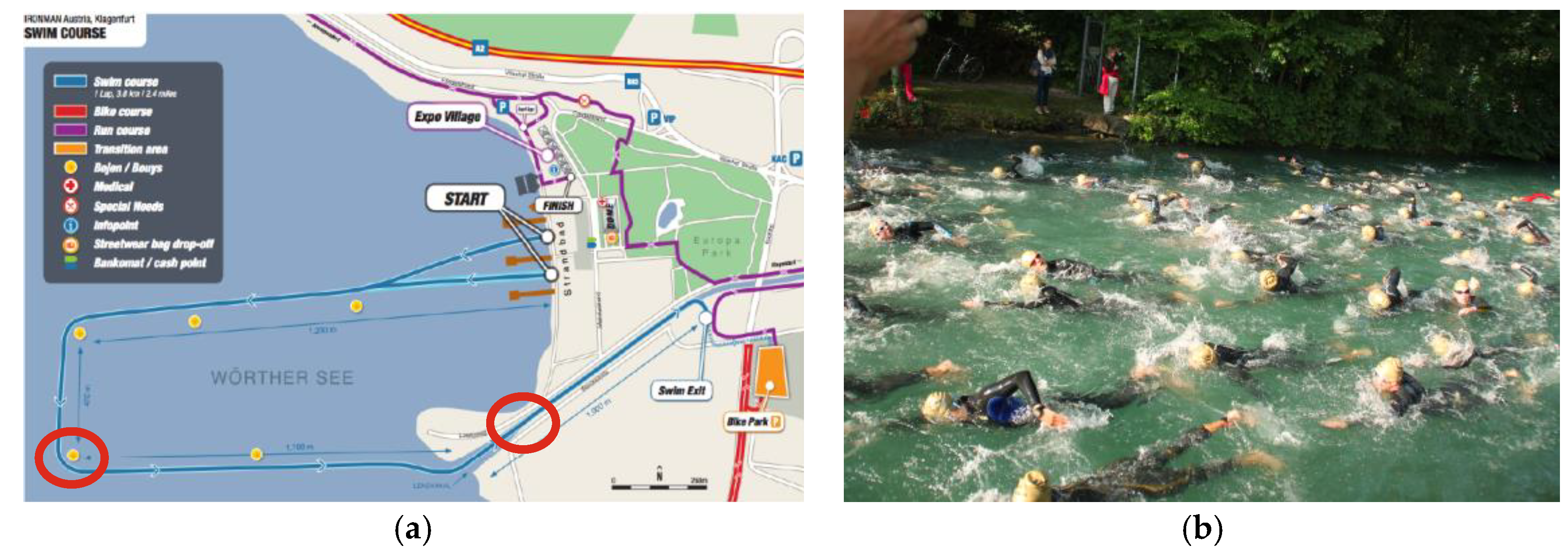
Some (active) RFID timing systems use frequencies that operate also in water or liquids without significant degradations in the detecting performance. The challenge is to find a tough device for the RFID antenna loop, which can be adapted to the required reading size in a flexible way and can be used in water for a certain time. The aim of this work is to show how a RFID timing system can be used in open water swimming competitions for split time reporting and pre-announcing. The athletes can be detected during their swimming performance without any notice but the device of the timing station is well secured against escort boats or small ships. Figure 1a shows the map of a swimming course at the Ironman Austria with two marked positions which are ideally situated to place a timing system. See Figure 1b to imagine the narrow channel crowded with athletic swimmers close to the second timing station.
1.2. Available Solutions
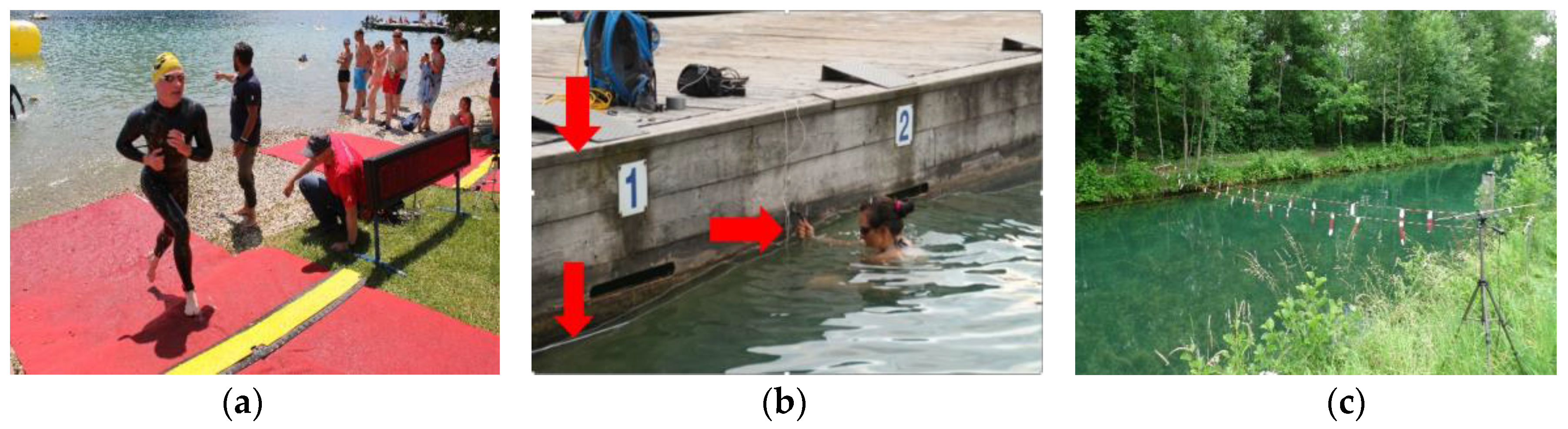
Figure 2 shows some other methods of RFID-timing arrangements for open water events or the swimming discipline in triathlons. An easy method is to insert a short land run between separated swimming sections (see Figure 2a). During this run a conventional floor mat timing system can be placed. When the outdoor swimming lane has an edge, like a pool, the RFID loop antenna can be mounted in vertical orientation (see Figure 2b). The short contact of the leg with the edge triggers the detection process. Figure 2c shows a very straight method of spanning the antenna cable over a narrow swimming channel. For offshore water timing close to turning buoys, the same method can be used but with an inflatable overhead system (see [2]). Table 1 gives a brief overview of the antenna placement and some further information.
2. Material and Methods
The goal of this work was to find a flexible device that could float in approximately 1.5 m depth under the water line so that the RFID detection process can take place completely under or small above the water surface. The athletes must not be affected by the underwater device. Following requirements have to be achieved:
- No metal inside the device components. The whole device must be able to swim in the water
- The device and all the components should be easily assembled, disassembled and reused.
- All parts of the device must be transportable inside a normal car.
2.1. Construction
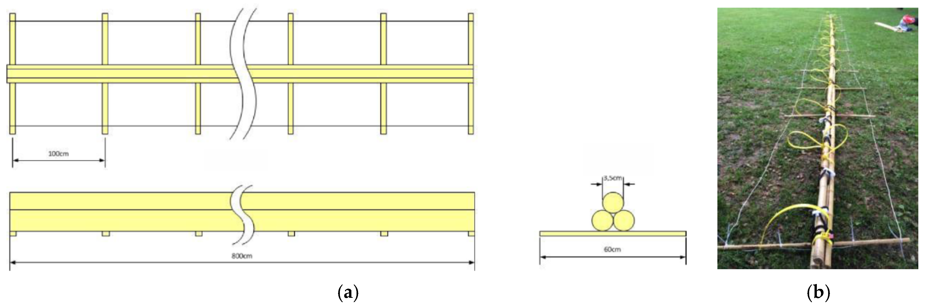
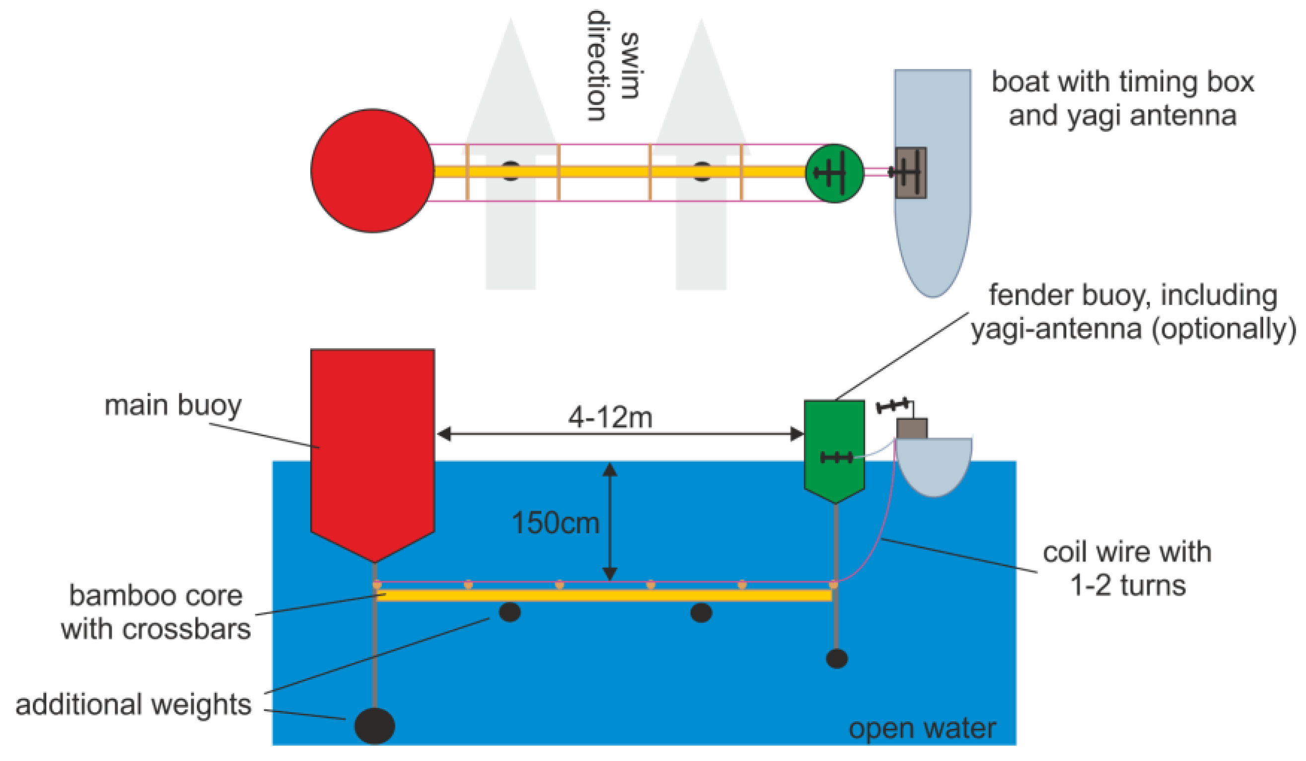
A suitable material for the underwater frame is bamboo or glass fiber reinforced plastic. The size of commercially available bamboo bars are 180 cm. Figure 3 shows the realized construction. The bars are arranged together to form a core with three staggered poles and fixed with reusable wire straps. The crossbars are attached to the core with rubber bands. At both outer ends of the crossbars, the wire of the inductive loop was fixed, again with wire straps but smaller ones and not reusable. Because of the bamboo with its natural cavities inside the bar, the whole construction can swim on the water surface. To make the design floating in a certain depth, it is burdened with a set of equally distributed stones along the bamboo core, see Figure 4. The distance from the surface is adjusted by the help of fender buoys on each end of the construction.
The timing system selected for this work is the active system ProChip from Mylaps and has its main use in triathlon events [3,4]. It is a dual frequency system and operates at the frequencies 125 kHz for the activation link (reader triggers the transponders) loop and 6.76 MHz for the detection link (transponders responds to the reader). Additionally, another dual frequency timing system could also be used: MTS J-Chip, with 125 kHz for activating the active transponder circuit and 433 MHz for receiving the ID information. The only difference was the separate set of Yagi antennas. These antennas had to be directed from the boat to the passing area between the buoys.
2.2. Calculations
To ensure that the bamboo core together with the coil wire is floating stationary, the force of the weight and the force of buoyancy must be in an equilibrium state. Bamboo contains an internal wood structure which leads to a net uplift force. In contrast, a set of stones as additional weight are fixed with ropes in regular distances. The main buoy with its huge body is not affected, but the immersion depth of the fender buoy must be calculated. Table 2 shows the corresponding calculations for a given amount of bamboo sticks and buoy size to determine the number of additional weights. For a required span size of 9 m between two buoys, there are 12 concrete stones necessary. It must be considered that the bamboo material reduces its volume after a while. The calculation neglects dynamic forces because of water flow. Stronger short time flows caused by a boat should not affect the construction substantially.
3. Results
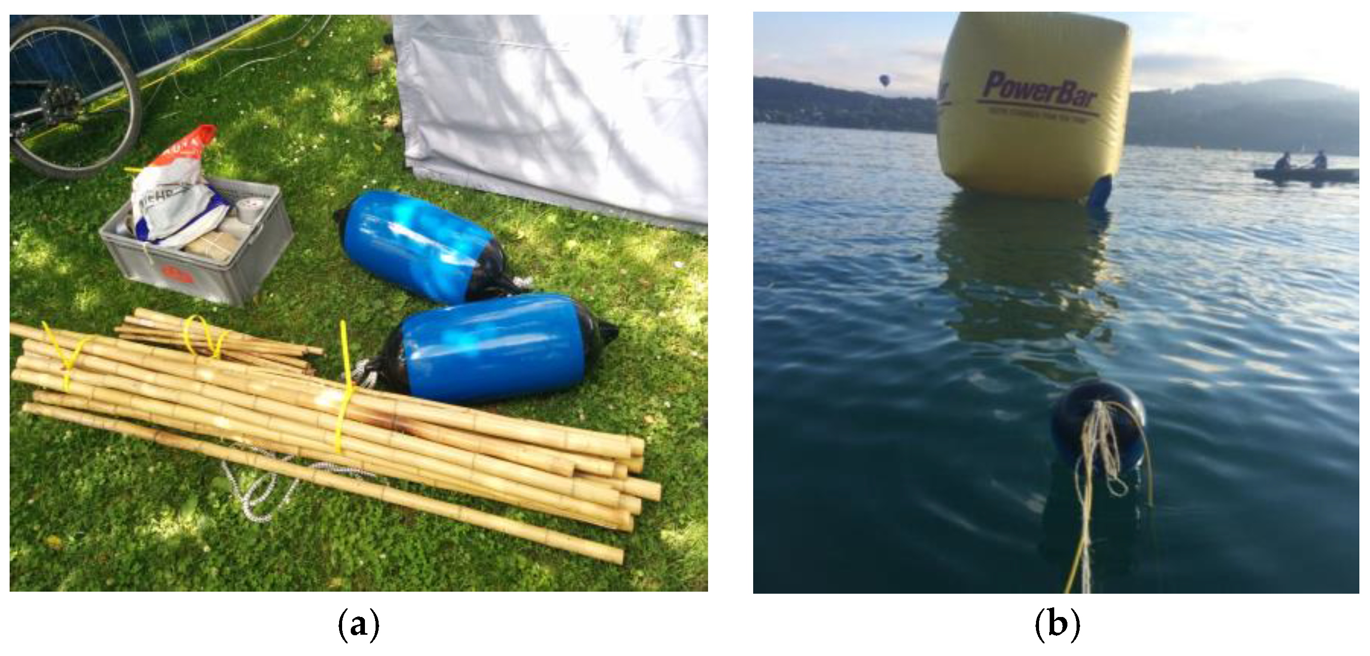
The device was developed and tested over a longer period of time. To get meaningful results with a big number of realistic RFID-detections, the test can only performed during a normal sport competition under the usual stressful conditions. Due to the good co-operation with some local sport organizers, it was possible to test it during different Ironman triathlon competitions (3800 m swim, 180 km cycle, 42 km run) and other triathlon and open water swim formats in Lake Wörthersee close to the city of Klagenfurt, AUT. Figure 5 shows the current setup with the disassembled components in Figure 5a and the operation inside the lake at the outer turning buoy, some moments before the first swimmer passes the timing gate, Figure 5b.
Measurements were evaluated by comparing the numbers of detection at the swimming finish line with numbers of detection at the water timing gate. Table 3 shows the detection rate of this system during all events. It ranges between 94.6% and 100% reading rate. This is a very high value because single timing systems (without backup) on the land promise a rate not better than 99%. One reason could be found during observing the first (and best) swimming athletes. Intermediate or athletic swimmers have a very flat position in the water. Their legs do not dive deeply into the water. Therefore, the guaranteed detection range must really reach from the antenna up to the water surface. This was not the case during the events Ironman AUT 2015 and Lendkanal Crossing 2016.
The reason for the alternating values can be found in the different quality levels during the installation process executed by different persons and the absence of a comprehensive testing method immediately before the competition starts. The continuation of this work deals with such testing and justifying processes.
4. Conclusions
This paper gives a possibility for performing timekeeping tasks of open water swimming competitions directly in the water. With some improvements at the concept, material, planning and co-ordination, a new kind of timing station can be possible. Necessary steps for the preparation are:
- Permanent communication between the timing team, organizer and the water rescue team.
- Assembling a ruggedized device that stands against water waves, weak collisions with boats and kicks off athlete’s feet.
- The device must be tied strongly to the main buoyage.
- The width of the timing gate should be suitable for the maximum number of passing athletes.
- The boat must have a safety distance to the beginning of the coil to avoid inductive inferences and to prevent athletes against collision with the boat.
- The service team should be trained to assemble and attach the construction precisely even under time pressure.
Despite the larger distance between the athlete’s RFID chip and the antenna, the reading reliability is as high as in normal operation situations. This is caused by the absence of any metallic or ferromagnetic material. The complete system was tested during big triathlon and open water swim events and will be enhanced for use in the following swimming season. But further measurements must be performed to analyze the reading rate behavior in saline (ocean) water.
References
- Finkenzeller, K. RFID Handbook: Fundamentals and Applications in Contactless Smart Cards and Identification, 2nd ed.; John Wiley & Sons Ltd.: Chichester, UK, 2003. [Google Scholar]
- RFID Race Timing System. Available online: www.rfidtiming.com (accessed on 11 June 2017).
- MYLAPS. MyLaps ProChip Manual. 2010. p. 15. Available online: http://support.mylaps.com/kb/en/b2b/Manuals/MyLaps_ProChip_Manual_Dec2010.pdf (accessed on 11 June 2017).
- Wöllik, H.; Müller, A.; Herriger, J. Permanent RFID Timing System in a Track and Field Athletic Stadium for Training and Analyzing Purposes. Procedia Eng. 2014, 72, 202–207. [Google Scholar] [CrossRef]
Figure 1.
(a) Map of the swimming course at the Ironman Austria (3800 m) with two preferred positions for placing a timing system; (b) During the last 800 m the swimmers have to pass a narrow channel. Here a water timing station can be used for pre-announcing the athletes at the swim finish.
Figure 1.
(a) Map of the swimming course at the Ironman Austria (3800 m) with two preferred positions for placing a timing system; (b) During the last 800 m the swimmers have to pass a narrow channel. Here a water timing station can be used for pre-announcing the athletes at the swim finish.

Figure 2.
Four different methods to use RFID-timing in open water sports. (a) Onshore running section between several laps of the swimming course; (b) Fixing the coil at an outdoor pool edge; (c) Overhead antenna loop over a narrow swimming channel
Figure 2.
Four different methods to use RFID-timing in open water sports. (a) Onshore running section between several laps of the swimming course; (b) Fixing the coil at an outdoor pool edge; (c) Overhead antenna loop over a narrow swimming channel

Figure 3.
Layout of the floating antenna coil construction with a bamboo core; (a) View along all three directions; (b) Picture of the built device.
Figure 3.
Layout of the floating antenna coil construction with a bamboo core; (a) View along all three directions; (b) Picture of the built device.

Figure 4.
The bamboo core as part of the completely timing system device with the view from top and along the swimmers direction. The core has a sufficient depth to permit the passing of boats between the buoys. All the electronic components are inside the timer’s boat, when using the MTS J-Chip system, a separate Yagi-antenna is necessary.

Figure 5.
(a) Components of the underwater timing antenna; (b) Operation in the lake, view from the timing boat, in the background the yellow turning buoy, in the foreground the fender buoy.
Figure 5.
(a) Components of the underwater timing antenna; (b) Operation in the lake, view from the timing boat, in the background the yellow turning buoy, in the foreground the fender buoy.


Table 1.
An overview of the different possibilities of RFID antenna placements for open water swimming events. LF = low frequency, typ. 125–132 kHz, HF = high frequency, typ. 6–433 MHz, DF = dual frequency (LF&HF), UHF = ultra-high frequency, typ. 860–960 MHz.
Table 1.
An overview of the different possibilities of RFID antenna placements for open water swimming events. LF = low frequency, typ. 125–132 kHz, HF = high frequency, typ. 6–433 MHz, DF = dual frequency (LF&HF), UHF = ultra-high frequency, typ. 860–960 MHz.
| Antenna Placement | Typical Gate Width | RFID-System | Complexity |
|---|---|---|---|
| Pool edge | 4–12 m | DF, active | simple |
| Overhead in channel | up to 15 m | DF, active | middle |
| Overhead offshore | up to 6 m | LF, HF, DF, active & passive | complex |
| Floor onshore | 2–4 m | LF, HF, DF, UHF, active & passive | simple |
| Floor in shallow water | 2–4 m | DF, active & passive | middle |
| Floating in deep water | up to 12 m | DF, active | complex |
Table 2.
Calculation of weight and uplift forces of the bamboo core and the additional weights (stones) to enable a stable floating in a certain depth for a span size of 9 m.
Table 2.
Calculation of weight and uplift forces of the bamboo core and the additional weights (stones) to enable a stable floating in a certain depth for a span size of 9 m.
| Quantity | Min | Typ | Max | Unit | Remark |
|---|---|---|---|---|---|
| vol. bamboo core VC | 13 | 26 | dm3 | 15 sticks, d = 35 mm, l = 180 cm (wet: volume reduces to half) | |
| vol. bamboo crossbars VCB | 0.4 | dm3 | 9 bars, d = 10 mm, l = 60 cm | ||
| vol. bamboo constr. VBCTot | 13.4 | 26.4 | dm3 | VBCTot = VC + VCB | |
| mass core and crossbars mC | 10.2 | kg | mC = VBCTot*ρC (ρC = 380 kg/m3) | ||
| weight core (force down) FDBC | 100 | N | FDBC = mC*g | ||
| uplift force FUBC | 131 | 259 | N | FUBC = ρW*VBCTot *g dens. of water ρW = 1000 kg/m3 | |
| net uplift force FUBCnet | 31 | 159 | N | FUBCnet = FUBC − FDBC | |
| vol. buoys VB | 63 | dm3 | 2 cylinder, d = 27 cm, h = 55 cm | ||
| mass buoys mB | 4.8 | kg | |||
| weight buoys FB | 47 | N | FB = mB*g | ||
| uplift force FUB | 618 | N | F = ρW*VB*g | ||
| uplift force partly dipped FUBpart | 206 | N | 1/3 of both buoys in water | ||
| net force buoys FUBnet | 159 | N | FUBnet = FUBpart − FB | ||
| uplift force total FUTot | 190 | 318 | N | FUTot = FUBnet + FUBCnet | |
| vol. stone VS | 1 | dm3 | concrete 20 × 10 × 5 cm | ||
| mass stone mS | 2.4 | kg | |||
| weight stone FS | 23.5 | N | FS = mS*g | ||
| uplift force stone FUS | 9.8 | N | FUS = ρW*VS*g | ||
| net weight stone FSnet | 13.7 | N | FSnet = FS − FUS | ||
| number of stones nS | 13 | 23 | nS = FUTot/FSnet equilibrium for floating |
Table 3.
Measurement results of the reading rate during different swimming competitions of past events.
Table 3.
Measurement results of the reading rate during different swimming competitions of past events.
| Competition | Passings | Reading Rate in % | Antenna Placements | Timing System |
|---|---|---|---|---|
| Ironman 5i50 AUT 2012 | 462 | 94.6 | Overhead in channel | J-Chip |
| Ironman AUT 2013 | 2640 | 100 | Floating in channel | Mylaps |
| Ironman AUT 2014 | 2723 | 100 | Floating in channel | Mylaps |
| Ironman AUT 2015 | 2498 | 98.7 | Floating in deep water | Mylaps |
| Open Water Swim AUT Lendkanal Crossing 2016 | 273 | 96.3 | 2× Floating in channel, 1× Overhead in channel | J-Chip |
| Open Water Swim AUT Lendkanal Crossing 2017 | 297 | 100 | 2× Floating in channel, 1× Overhead in channel | J-Chip |
Publisher’s Note: MDPI stays neutral with regard to jurisdictional claims in published maps and institutional affiliations. |
© 2018 by the author. Licensee MDPI, Basel, Switzerland. This article is an open access article distributed under the terms and conditions of the Creative Commons Attribution (CC BY) license (https://creativecommons.org/licenses/by/4.0/).
Share and Cite
MDPI and ACS Style
Woellik, H. RFID Timing Antenna for Open Water Swimming Competitions. Proceedings 2018, 2, 300. https://doi.org/10.3390/proceedings2060300
AMA Style
Woellik H. RFID Timing Antenna for Open Water Swimming Competitions. Proceedings. 2018; 2(6):300. https://doi.org/10.3390/proceedings2060300
Chicago/Turabian StyleWoellik, Helmut. 2018. "RFID Timing Antenna for Open Water Swimming Competitions" Proceedings 2, no. 6: 300. https://doi.org/10.3390/proceedings2060300