Proceeding Paper

Characterization of the Bond between Textile Reinforced Cement and Extruded Polystyrene by Shear Tests †

Mechanics of Materials and Constructions (MeMC), Vrije Universiteit Brussel, 1050 Brussels, Belgium
*
Author to whom correspondence should be addressed.
Presented at the 18th International Conference on Experimental Mechanics, Brussels, Belgium, 1–5 July 2018.
Proceedings 2018, 2(8), 419; https://doi.org/10.3390/ICEM18-05275
Published: 27 May 2018
(This article belongs to the Proceedings of The 18th International Conference on Experimental Mechanics)

Abstract

:
Loadbearing sandwich panels used as wall elements are a promising development since they combine structural and energy efficiency. Composite behaviour needs to be ensured so that the sandwich panel works as one element under a flexural load (meaning that the shear forces due to bending are transferred from one face to the other). To assure this full composite behaviour, an investigation of the bond strength between the faces and the core of the sandwich panel is necessary. Therefore, two different bond test set-ups were performed on sandwich panels with Textile Reinforced Cement (TRC) faces and an Extruded Polystyrene (XPS) insulating foam core. The two bond test set-ups were compared and revealed that one of the set-ups showed a combination of bond and shear failure of the core so that a clear conclusion on the bond strength couldn’t be obtained. The second set-up showed clear bond failure and gave a good estimation of the bond strength between TRC and XPS.

1. Introduction

Nowadays, Nearly Zero Energy Buildings are emerging in construction industry since new European regulations try to increase the energy efficiency of future and existing buildings. The design and construction of those buildings is only possible when innovative energy efficient building elements are developed like for example, insulated sandwich panels with Textile Reinforced Cement (TRC) faces. TRC sandwich panels are composed of a rigid insulating core surrounded by two stiff TRC faces. These TRC faces are composed, in turn, of a cement matrix and a textile reinforcement. TRC sandwich panels combine structural – and energy efficiency in one element, since the TRC faces provide the necessary loadbearing capacity while the insulating core improves the energy efficiency of the element. This loadbearing capacity can be enhanced by ensuring a full composite behaviour, meaning that both faces are working together to resist the applied forces [1]. To ensure this composite behaviour the bond between the faces and the core is crucial.
Related works on testing the bond properties are mostly dedicated to the bond between TRC and concrete since up to now strengthening and formwork for concrete structures have a largest application field of TRCs [2,3,4]. Different ways of testing the shear capacity of this TRC-concrete bond are proposed and are mostly based on double-lap shear tests. Only Horstmann et al. [5], and Shams et al. [1] performed bond tests on TRC sandwich panels with a foamed Polyurethane (PU) core by a double-lap shear test.
In this paper the results from two different shear bond test set-ups between TRC and Extruded Polystyrene (XPS) are presented. The set-ups were compared so that the most appropriate one (only debonding failure) could be defined for further research on the bond between TRC and XPS.

2. Materials and Methods

2.1. Textile Reinforced Cement

TRC is a composite material composed of a cementitious matrix and a textile reinforcement. The matrix used in this research is a commercially available self-compacting mortar with an E-modulus of 12.5 GPa and a compressive strength of 60 MPa according to the supplier [6]. The used textile reinforcement is an E-glass fibre 3D spacer textile with a density of 623 g/m³ and a spacer distance of 10 mm [7].

2.2. Extruded Polystyrene
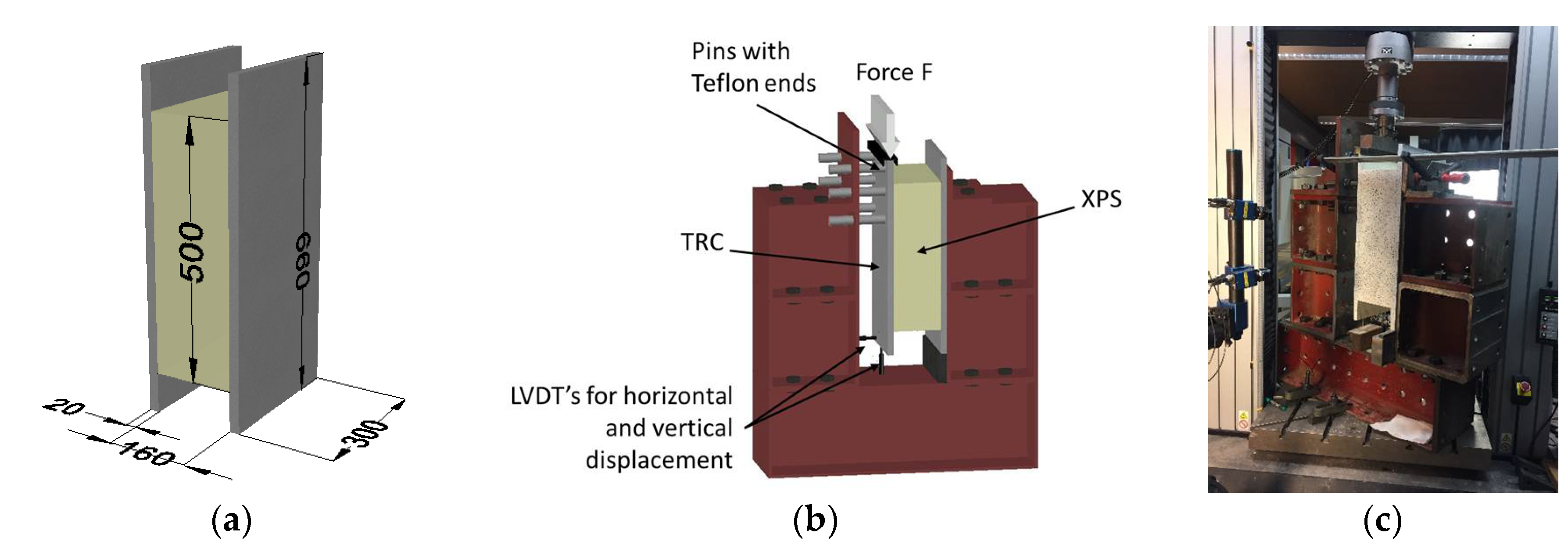
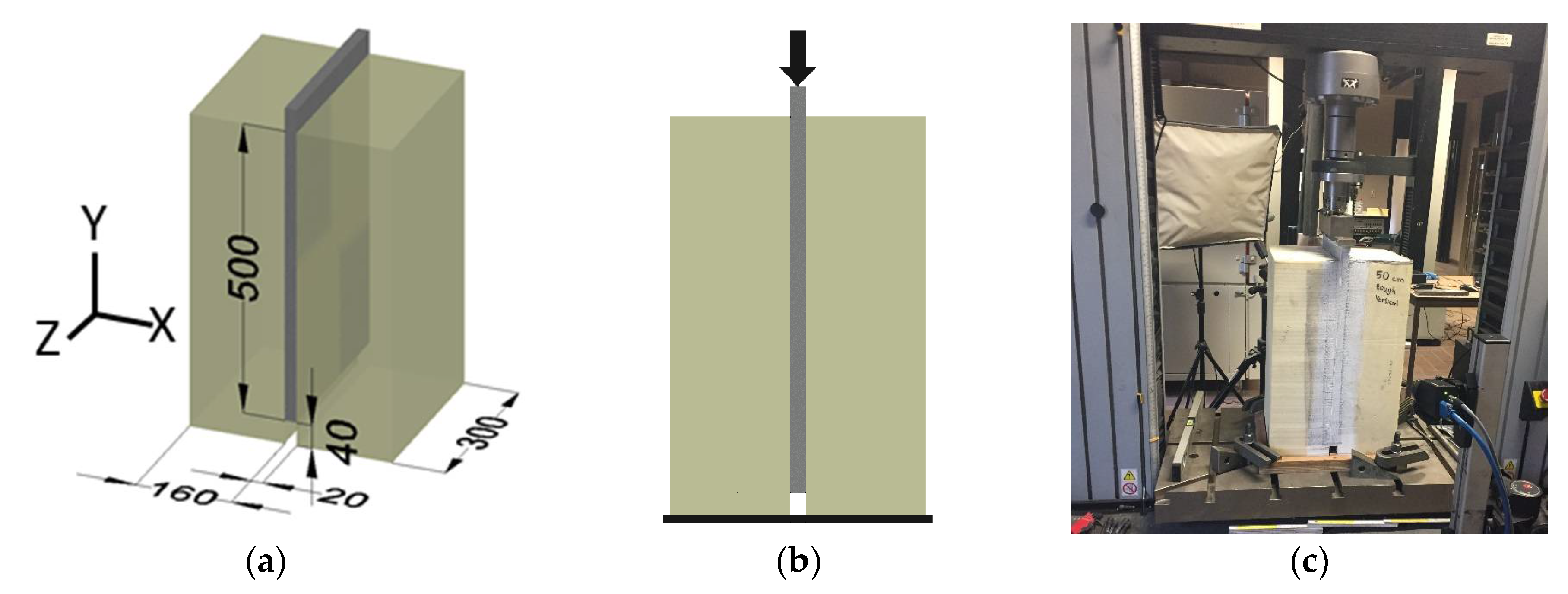
The insulating foam used for this paper is XPS as foam blocks with a thickness of 160 mm, a density of 33 kg/m³ and a rhombus grid surface finishing. The E-modulus and compressive strength (9.1 MPa and 13.5 kN respectively) were determined by the average of X compression tests on cubic foam blocks with sides of 160 mm. The shear modulus of the XPS foam, 4.3 MPa, was determined according to NBN EN 14509 (2013) [8] with a four-point bending test on three specimens.

2.3. Test Set-Ups

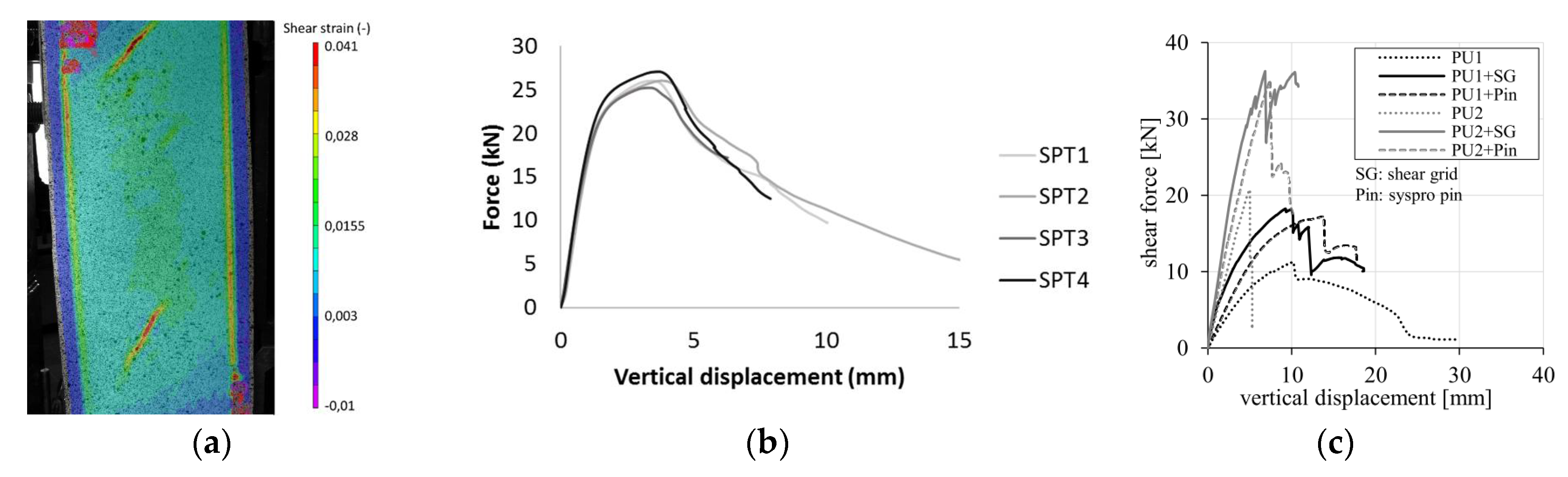
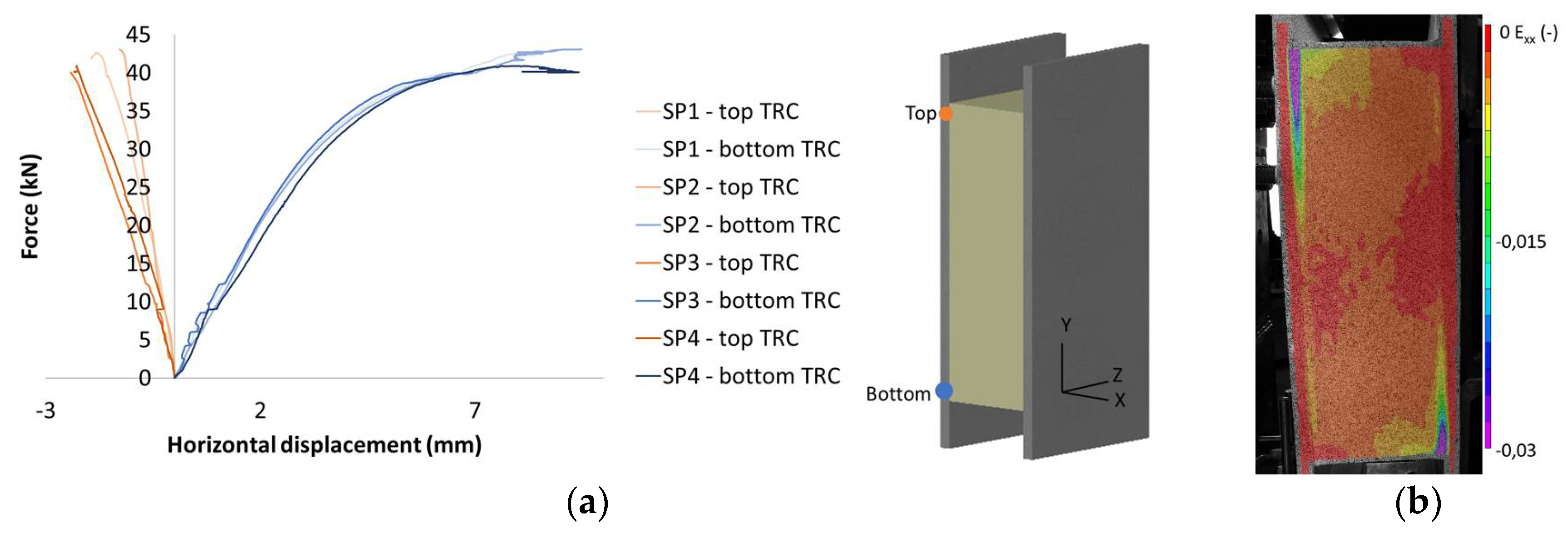
2.3.1. Double-Lap Shear Test According to Shams et al.

The first test set-up is based on the shear tests performed by Shams et al. [1] which is a double-lap shear test. The specimens for this set-up are composed of two TRC layers with an insulation block in between, resembling the configuration of the final application, namely sandwich panels. One of the faces is supported at the bottom with a steel beam while the other face can move freely in the vertical direction but is supported in the horizontal direction by steel tubes with a Teflon end. These Teflon ends assure minimal friction between the panel and the tubes. The force is applied on the face that is not supported in the vertical direction (Figure 1). The tests were monitored on both sides with the full field measuring technique Digital Image Correlation (DIC) which is a non-destructive technique that measures the displacement of the specimen according to a reference image. Next to DIC, two LVDT’s are used, one to measure the vertical displacement of the bottom of the loaded face and one to measure the horizontal displacement at the bottom of the loaded face to verify the results of DIC.

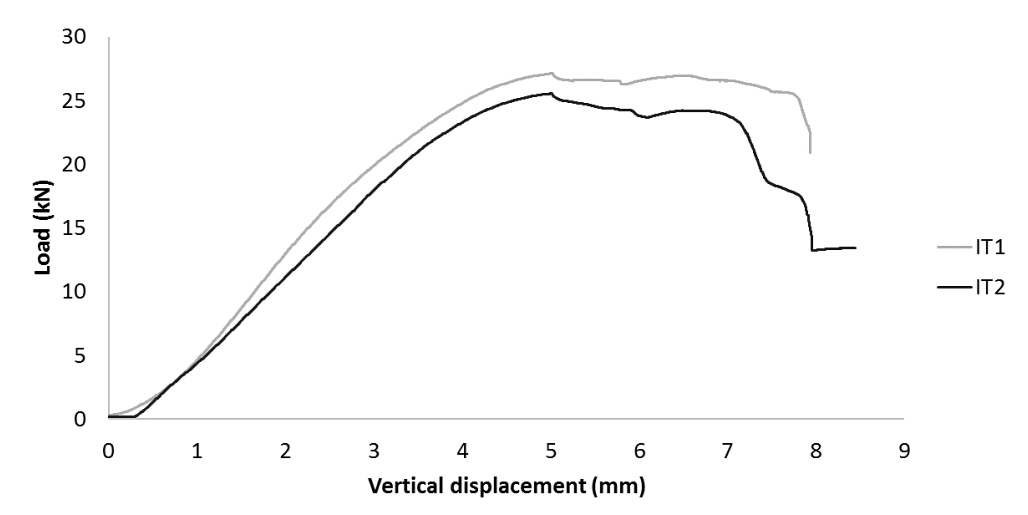
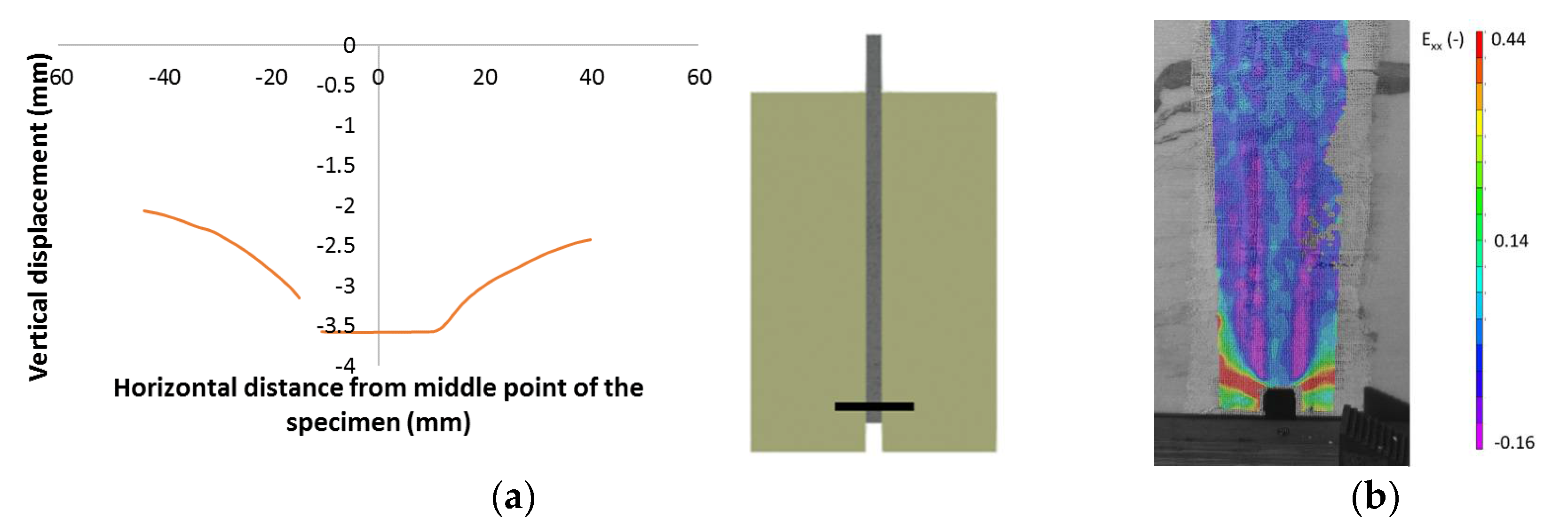
2.3.2. Inserted Type

The second bond test is designed according to the set-up of Wozniak et al. [4] for the bond between TRC and concrete and is much easier to produce than the previous one. The specimens for this set-up are composed of two insulation blocks with a TRC plate in between (Figure 2a). The bonded area of this type of specimen is the same as for the previous double-lab shear test. The two foam blocks are restricted in the X and Z direction at the bottom of the specimen. The load is applied on the TRC plate by means of a steel beam (Figure 2b,c). Also for this set-up the displacement of both sides of the specimens was monitored by DIC.

2.4. Production Method

The production method of the specimens depended on the used test set-up. The specimens for the double-lap shear test (which is described in Section 2.3.1) were made in a few steps. First the insulation was placed into the mould on which a thin layer of cement was casted. Then the textiles were put in place and the rest of the cement was poured on the textile until the mould was filled. The mould was covered and turned 180° after one day so that the second face could be casted in the same way as the first one. For the second specimen type (see Section 2.3.2) the cement was poured vertically between two foam blocks after positioning the textile in-between.

3. Results

3.1. Double-Lap Shear Test

In Figure 3a the force-displacement curves of four identical double-lap shear tests are given. The vertical displacement is the displacement at the top of the loaded face measured by the DIC. All specimens gave comparable results with a maximum load around 40 kN. A high ductility was noticed except for specimen 4. This is due to the loss of DIC data as a consequence of large deformations. Figure 3b shows a representative specimen at failure where a combination of shear failure of the core and debonding between the core and a face was noticeable.
Analysis of the DIC results provided the complete displacement (and consequently strain) field of the specimens’ surface. The horizontal displacement of the loaded TRC face at the bottom of the specimen proved to be significant (Figure 4a) and led to the compression of the foam at the interface with the TRC face. This horizontal compression increased the friction between the foam and the TRC face, leading to an inhibition of the debonding phenomenon and a reduced debonding speed after initiation.
To investigate what exactly happens during the test, the vertical displacement at the interface and the shear strain of the foam were investigated. The vertical displacement was plotted for four different lines crossing the interface between the TRC face and the foam at the four corners of the foam (Figure 5a) at a load of 22 kN. A sudden shift of 0.02 mm in the vertical displacement over a horizontal distance of 1 mm was observed for the top left corner (L0—loaded end), indicating that the debonding initiates around 25kN (Figure 5).
After this first initiation of debonding, shear of the core became visible and further development of the debonding was prohibited by the horizontal compression discussed above. At the maximum load of the test (±40 kN at Figure 3a) the core failed in shear since the ultimate shear strain (0.041 calculated from the shear force and shear modulus given in Section 2.2) was reached (Figure 6a). After the core failed in shear, debonding also started at lines L1 and L2 (Figure 5) with a final failure by complete detachment of the foam from the TRC as a result (Figure 3b).
The same test was also performed on sandwich panels with a thinner core of 20 mm instead of 160 mm. Figure 6b shows the force-displacements curves of the different specimens. If the maximal load and displacement were compared with the previous specimens with thicker core a reduction for both the maximal load and displacement was observed. This emphasizes the influence of the core on the test set-up.
The results of the test performed in the scope of this paper are compared with the one of the double-lab shear test on polyurethane (PU) performed by Shams et al. [1]. In Figure 6c PU1 represents polyurethane with a density of 50 kg/m³, PU2 polyurethane with a density of 100 kg/m³. Since the experiments performed in the scope of this paper had no shear grid or pin connector and the properties of XPS are closest to PU1 a comparison was made between the results of this paper and the one of PU1 in Figure 6c. The thickness of the core was also 160 mm for the experiments performed by Shams et al. [1]. Comparison of the results showed a better shear bond for the XPS then for the PU. This improved behaviour could be due to the profiled finishing of the XPS blocks (like described in Section 2.2) which provides mechanical interlocking.

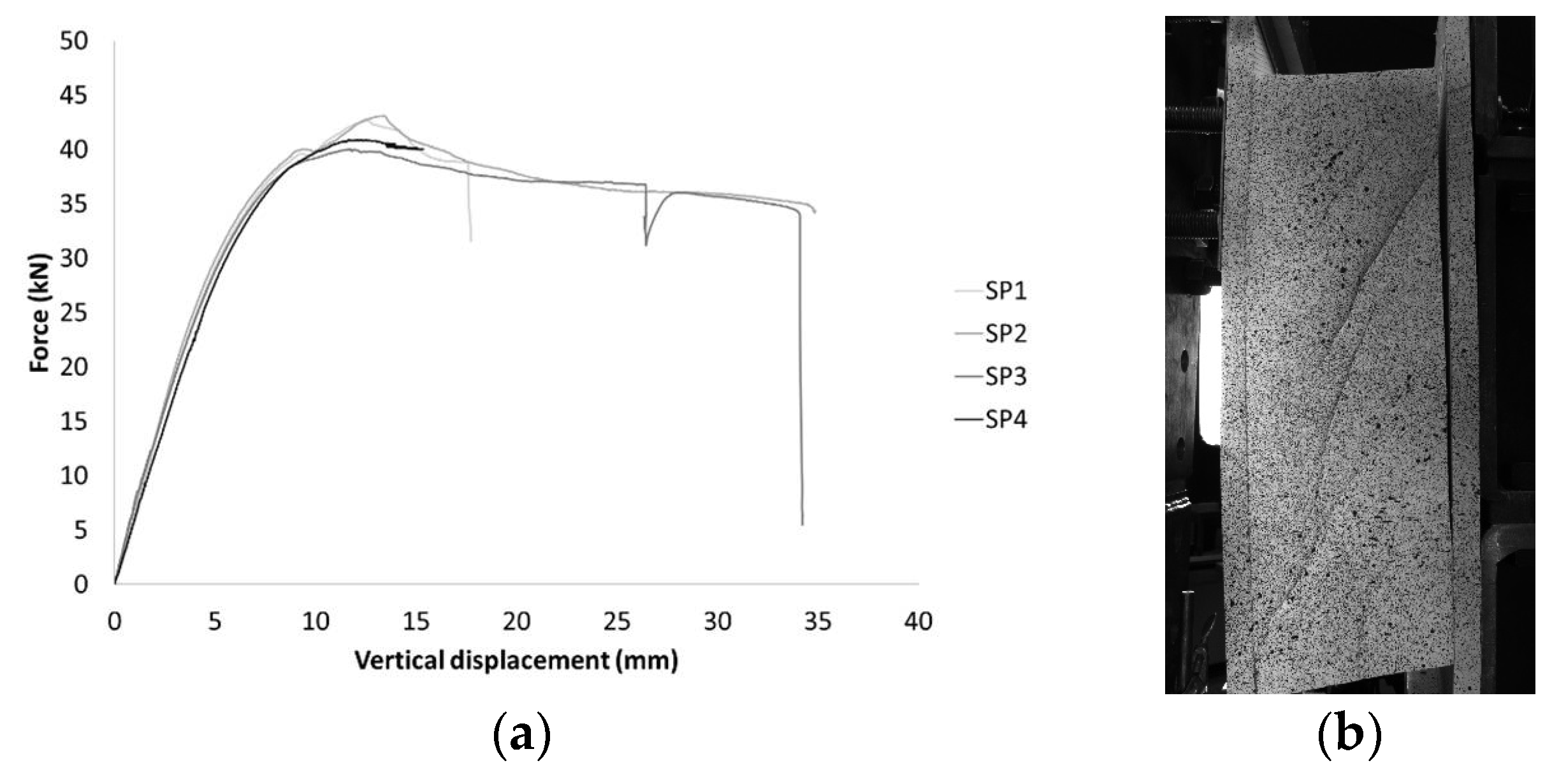
3.2. Inserted Type Set-Up

For the second set-up, the inserted type, the ultimate strength reached up to 26 kN which was similar to the load where the first debonding happened during the double-lap shear test (Figure 7). However, the ductility is less for the inserted type than for the double-lap shear test.
Figure 8a shows the vertical displacement taken on a line drawn at the bottom of the specimen. As soon as debonding started (±20 kN) the line of the vertical displacement shows a discontinuity. A closer look on the strain in the horizontal direction (Exx) showed that failure by debonding is followed by compression at the interface (Figure 8). Shear debonding occurred at a value of 20 kN for the inserted type specimen and at 22 kN for the double-lab shear test. Since the bonded area is the same for both specimen similar debonding stress were reached for both types of specimen.

4. Conclusions

In terms of production method, the inserted type specimens were easier than the double-lap shear specimens since the latter needed to be casted in two days, while the first ones were casted in one single step. The failure happened in different stages, starting with debonding at the loaded side followed by compression at the interface, shear failure of the core and finally failure by complete debonding at supported side. In contrast, the second set-up showed a clear debonding failure, initiated at a similar bond stress, without shear of the insulation. As a conclusion it can be stated that the second set-up was more suitable for testing the bond between TRC and XPS.

Author Contributions

J.V. and P.K. conceived, designed and performed the experiments, analysed the data and wrote the paper, the others did a first review on the paper.

Acknowledgments

The authors gratefully acknowledge Agentschap voor Innovatie en Ondernemen (VLAIO) for funding the research.

Conflicts of Interest

The authors declare no conflict of interest. The funding sponsors had no role in the design of the study; in the collection, analyses, or interpretation of data; in the writing of the manuscript, and in the decision to publish the results.

References

  1. Shams, A. A Novel Approach for the Production and Design of Load-Carrying Sandwich Panels with Reinforced Concrete Facings; RWTH Aachen: North Rhine-Westphalia, Germany, 2015. [Google Scholar]
  2. D’Ambrisi, A.; Feo, L.; Focacci, F. Experimental analysis on bond between PBO-FRCM strengthening materials and concrete. Compos. Part B Eng. 2013, 44, 524–532. [Google Scholar] [CrossRef]
  3. Ortlepp, R.; Hampel, U.; Curbach, M. A new approach for evaluating bond capacity of TRC strengthening. Cem. Concr. Compos. 2006, 28, 589–597. [Google Scholar] [CrossRef]
  4. Wozniak, M.; Tysmans, T.; Verbruggen, S.; Vantomme, J. Quality of the bond between a Strain Hardening Cement Composite stay-in-place formwork and concrete: Comparison of two experimental set-ups. Constr. Build. Mater. 2017, 146, 764–774. [Google Scholar] [CrossRef]
  5. Horstmann, M. Zum Tragverhalten von Sandwichkonstruktionen aus Textilbewehrtem Beton; RWTH Aachen: North Rhine-Westphalia, Germany, 2010. [Google Scholar]
  6. Sika. Sikagrout-217 Fine Concrete Data Sheet; Sika: Le Bourget, France, 2017; pp. 818–821. [Google Scholar]
  7. Fraas, V. SITgrid701 Datenblatt. 2017. [Google Scholar]
  8. British Standards Institute. EN 14509: Self-Supporting Double Skin Metal Faced Insulating panels—FACTORY Made Products—Specifications; British Standards Institute: London, UK, 2013. [Google Scholar]
Figure 1. (a) specimen geometry and dimensions in mm; (b) schematic presentation of the double-lap shear test; (c) picture of double-lab shear test.
Proceedings 02 00419 g001
Figure 2. (a) specimen geometry with dimensions in mm; (b) schematic presentation of the test set-up; (c) picture of the test set-up.
Proceedings 02 00419 g002
Figure 3. (a) force-displacement curve of the double-lap shear test; (b) picture of specimen at failure.
Proceedings 02 00419 g003
Figure 4. (a) horizontal displacement (x-direction) of the top and bottom of the loaded TRC face; (b) compression at the interface.
Proceedings 02 00419 g004
Figure 5. Initiation of debonding (line L0) at a load of 22kN.
Proceedings 02 00419 g005
Figure 6. (a) shear failure at a load of 40 kN; (b) force-displacement curve of the double-lap shear test with a thinner core of 20 mm; (c) double-lap shear test performed by Shams et al. [1].
Proceedings 02 00419 g006
Figure 7. Load-displacement curves of inserted type bond test.
Proceedings 02 00419 g007
Figure 8. (a) debonding starting at the bottom of the specimen; (b) compression at the interface before debonding.
Proceedings 02 00419 g008
Publisher’s Note: MDPI stays neutral with regard to jurisdictional claims in published maps and institutional affiliations.

