Proceeding Paper

Digital Image Correlation Measurements of Mode I Fatigue Delamination in Laminated Composites †

1
Department of Materials Engineering, KU Leuven, 3001 Leuven, Belgium
2
SIM M3 program, 9052 Zwijnaarde, Belgium
3
Department Mechanics of Materials and Constructions, Vrije Universiteit Brussel, 1050 Brussels, Belgium
4
Siemens PLM Software, 3001 Leuven, Belgium
*
Author to whom correspondence should be addressed.
Presented at the 18th International Conference on Experimental Mechanics (ICEM18), Brussels, Belgium, 1–5 July 2018.
Proceedings 2018, 2(8), 430; https://doi.org/10.3390/ICEM18-05289
Published: 4 June 2018
(This article belongs to the Proceedings of The 18th International Conference on Experimental Mechanics)

Abstract

:
A Digital Image Correlation (DIC) based method is proposed to characterize Mode I fatigue delamination onset and propagation in laminated composites. With the help of DIC, the displacement field around a delamination crack is obtained and further processed to determine the position of the crack tip. With this method the delamination length can be measured automatically in each cycle with a precision on the order of few hundreds of micrometers. The fatigue delamination onset life is then determined by detecting the increase of the delamination length, and the fatigue delamination propagation rate is calculated. The proposed method produces more conservative fatigue life measurements in comparison with the compliance increase method in ASTM D6115.

1. Introduction

Digital image correlation (DIC) is a popular tool to measure deformation on the surface of a material. One of its appealing features is the capability to detect highly heterogeneous displacement fields and strain maps. This advantage makes DIC interesting for characterization of materials that involve discontinuities, for example, for estimation of stress intensity factors [1], detection of the crack path [2] and general observation of failure in composites [3,4].
Susceptibility to delamination is one of the major drawbacks of laminated composites. Fatigue delamination onset and propagation tests are commonly adopted to measure the number of cycles to onset the delamination (N) and the rate of its propagation under certain levels of load. At present, the fatigue delamination onset test for Mode I is commonly performed according to ASTM D6115 standard [5], which is the only standard available to characterize fatigue delamination in composites. In this standard, the onset life, Nonset, is determined by monitoring a 1% or 5% increase in the compliance of the system. The downside of this approach is that the compliance integrates all the information on sample deformation and does not precisely correlate with the crack tip movement, therefore the compliance-based method is prone to errors [6]. For the fatigue delamination propagation, there is no standard for composites so far. The delamination length during the cycles is normally measured manually using a travelling microscope, which is operator-dependent and time-consuming. Automatic and precise measurement of delamination propagation under fatigue loading is required for characterization of the fatigue delamination behavior of composites.
In this paper we propose a new method for processing of the DIC-measured displacement and strain fields at the edge of the Mode I specimen to characterize the length of the delamination in onset and propagation fatigue tests. Through DIC, it is possible to automatically detect the crack growth during the fatigue loading. The accuracy of the crack tip position obtained from DIC is verified by microscopy observations.

2. Material and Methods

2.1. Material and Test Procedures

The composite laminates used in this work were produced using PYROFILTM TR 360E250S carbon/epoxy (Mitsubishi Chemical Corporation). The panels were made of 18-ply unidirectional prepregs and a 12.5 μm PTFE film was placed between 9th and 10th plies to create an initial delamination. The stack sequence of the laminate was [09/Insert/09]. The specimens were nominally 150 mm long, 25 mm wide and 4.2 mm thick. The length of insert is about 50 mm, measured from load block centre. The speckle patterns were applied at the edge of the specimens for the DIC processing.
To characterize Mode I fatigue delamination behavior, double cantilever beam (DCB) tests were utilized. The specimens were loaded under a constant displacement amplitude with the ratio of minimum/maximum displacement R = 0.1. The maximum strain energy release rate was between 30% and 60% of the mode I fracture toughness. The applied maximum displacement was in the range 1.81 to 1.05 mm, defined for each test based on the specified Gmax, specimen width and the pre-crack length, using the formulae in ASTM D6115 [5]. The frequency of the fatigue test was 10 Hz. Images of the fatigue delamination on one side of the specimen were automatically recorded at a maximum displacement at specific fatigue cycles.

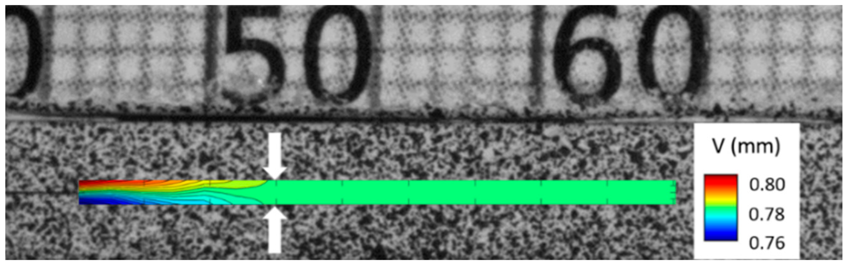
2.2. Crack Tip Detection with DIC

A commercial software Vic-3DTM was used to calculate the displacement field at the edge of DCB specimens. The image had the resolution of 1 pixel = 37 μm. The vertical displacement, V, around the delamination crack was obtained, as shown in Figure 1. At the position where the crack exists (from ~46 to ~51 mm), obvious variation of vertical displacement was observed through the specimen thickness because of the crack opening. This variation gradually decreases to zero at ~52 mm, which indicates the end of the crack. Therefore, this zero variation of vertical displacement around the crack path is used as a criterion of determining the crack tip position.

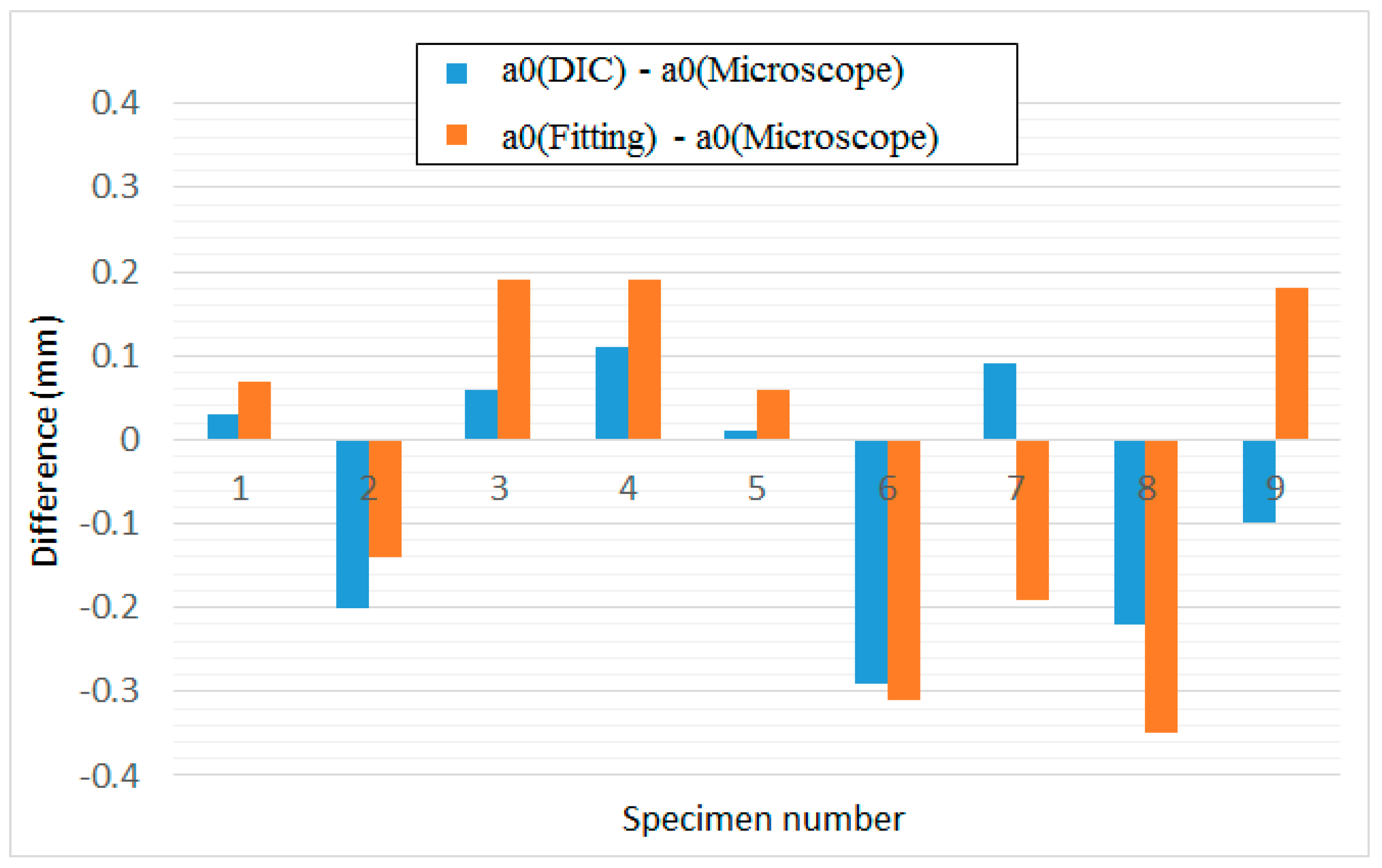
2.3. Determination of Fatigue Onset Life

Based on the crack tip detection method briefly described in Section 2.2, delamination length, a, versus the number of loading cycles, N, is obtained. The fatigue onset life, Nonset, is then determined by detecting the moment when the delamination length starts growing. A piece-wise function (Equation (1)) is used to describe the constant delamination length before Nonset and its growth after onset:
x = f ( N ) = { a 0 , N N onset α ( N N onset ) + a 0 , N > N onset ,
R 2 = i [ f ( N i ) x i ] 2 min ,
where a0 and Nonset stand for the initial crack length and fatigue onset life, and α represents the rate of crack growth. Ni and xi are the number of cycles and delamination length obtained from DIC detection, respectively. Before the fatigue onset life, Nonset, is reached, the crack doesn’t grow and its tip stays at the initial position a0. Therefore a constant function was adopted when NNonset. A simple linear fitting function was used to describe the crack growth when N > Nonset. The fitting parameters were determined according to the least square method R2 (Equation (2)).

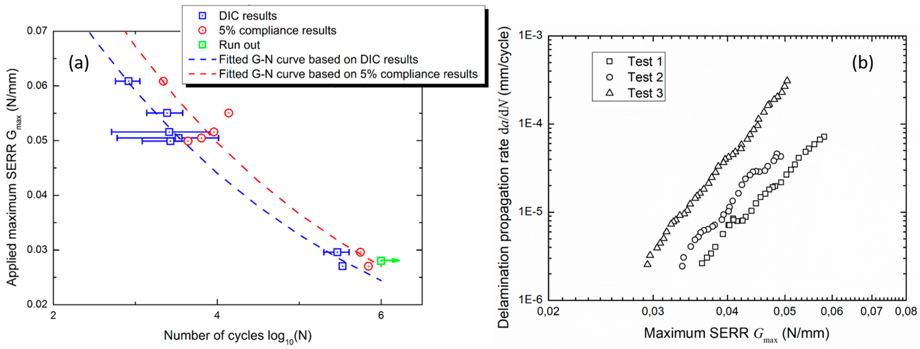
2.4. Detection of Fatigue Delamination Propagation

The increase of delamination length after fatigue onset life Nonset was used to describe the fatigue delamination propagation. A parsing routine was firstly applied to the raw data to eliminate the noise. The crack growth curve after parsing processing was then used to calculate the delamination propagation rate da/dN during the fatigue loading. A 7-point incremental polynomial method was used to calculate da/dN, as recommended in ASTM E647 [7]. A log-log plot of crack propagation rate (da/dN) versus the maximum applied SERR Gmax was produced to describe the fatigue delamination propagation behavior, as done in Refs. [8,9].

3. Results and Discussion

The crack tip detection with DIC was applied to nine different tests, and the initial crack tip position measured from the first cycles, a0(DIC), was recorded. To verify the proposed method, the initial crack length was also measured using microscopy, a0(Microscope), and then compared to a0(DIC). Figure 2 shows the difference between the DIC detection results and microscope observation. The fitted initial crack length, a0(Fitting), was also used to verify the accuracy of Equation (1). It indicates that DIC detection and fitted initial crack length both exhibit a good accuracy, which differs from microscope observation by less than 0.36 mm.
G-N curves and propagation rate curves are produced based on the DIC-based measurement of the crack length, as shown in Figure 3a,b, respectively. The G-N curve obtained from the compliance monitoring method recommended in the standard [5] is also provided for comparison (Figure 3a). It shows that the fatigue delamination onset life, Nonset, obtained from the DIC measurement is significantly lower than that from the compliance monitoring method. The DIC measurement links the growth of the crack to the real displacement field around the crack tip, and produces more conservative results for fatigue life than the compliance monitoring method recommended in the standard.

4. Conclusions

A DIC-based method is proposed to detect Mode I fatigue delamination onset and propagation. The DIC detection of propagating delamination shows high accuracy compared with microscopic observation. The fatigue onset life obtained from the DIC measurement is lower than that based on 5% of the compliance increase. This proposed method provides a way to detect the delamination propagation automatically during the fatigue tests.

Author Contributions

The team at VUB (S.F., L.P. and D.V.H.) conceived and designed the fatigue experiments; S.F. performed the fatigue experiments and DIC data acquisition; the team at KULeuven (M.Z., L.G. and S.V.L.) developed the DIC-based data analysis method, analyzed the data and interpreted results; D.C.-P. from Siemens contributed to the analysis of the results; M.Z. wrote the paper.

Acknowledgments

The work leading to this publication has been funded by the SBO project “M3Strength”, which fits in the MacroModelMat (M3) research program funded by SIM (Strategic Initiative Materials in Flanders) and VLAIO (Flanders Innovation & Entrepreneurship). We would like to thank Siemens (Siemens PLM Software, Belgium), Honda (Honda R&D Co., Ltd.) and Mitsubishi (Mitsubishi Chemical Corporation) for all the support.

Conflicts of Interest

The authors declare no conflict of interest. The funding sponsors had no role in the design of the study; in the collection, analyses, or interpretation of data; in the writing of the manuscript, and in the decision to publish the results.

References

  1. McNeill, S.R.; Peters, W.H.; Sutton, M.A. Estimation of stress intensity factor by digital image correlation. Eng. Fract. Mech. 1987, 28, 101–112. [Google Scholar] [CrossRef]
  2. Lee, D.; Tippur, H.; Kirugulige, M. Experimental study of dynamic crack growth in unidirectional graphite/epoxy composites using digital image correlation method and high-speed photography. J. Compos. Mater. 2009, 43, 2081–108. [Google Scholar] [CrossRef]
  3. Mehdikhani, M.; Matveeva, A.; Aravand, M.A.; Wardle, B.L.; Lomov, S.V.; Gorbatikh, L. Strain mapping at the micro-scale in hierarchical polymer composites with aligned carbon nanotube grafted fibers. Compos. Sci. Technol. 2016, 137, 24–34. [Google Scholar] [CrossRef]
  4. Lomov, S.V.; Ivanov, D.S.; Verpoest, I.; Zako, M.; Kurashiki, T.; Nakai, H.; Molimard, J.; Vautrin, A. Full field strain measurements for validation of meso-FE analysis of textile composites. Compos. Part A 2008, 39, 1218–1231. [Google Scholar] [CrossRef]
  5. ASTM D6115-97(2011), Standard Test Method for Mode I Fatigue Delamination Growth Onset of Unidirectional Fiber-Reinforced Polymer Matrix Composites; ASTM International: West Conshohocken, PA, USA, 2011.
  6. Bak, B.L.V.; Sarrado, C.; Turon, A.; Costa, J. Delamination under fatigue loads in composite laminates: A review on the observed phenomenology and computational methods. Appl. Mech. Rev. 2014, 66, 060803. [Google Scholar] [CrossRef]
  7. ASTM E647-15e1, Standard Test Method for Measurement of Fatigue Crack Growth Rates; ASTM International: West Conshohocken, PA, USA, 2015.
  8. Stelzer, S.; Brunner, A.J.; Argüelles, A.; Murphy, N.; Pinter, G. Mode I delamination fatigue crack growth in unidirectional fibre reinforced composites: Development of a standardized test procedure. Compos. Sci. Technol. 2012, 72, 1102–1107. [Google Scholar] [CrossRef]
  9. Asp, L.E.; Sjogren, A.; Greenhalgh, E.S. Delamination growth and thresholds in a carbon/epoxy composite under fatigue loading. J. Compos. Technol. Res. 2001, 23, 55–68. [Google Scholar]
Figure 1. Vertical displacement field around the delamination by DIC analysis in Mode I test.
Proceedings 02 00430 g001
Figure 2. Comparison of initial crack tip positions with different techniques.
Proceedings 02 00430 g002
Figure 3. Mode I delamination: (a) G-N curves from DIC method and compliance method; (b) fatigue delamination propagation rate curve.
Proceedings 02 00430 g003
Publisher’s Note: MDPI stays neutral with regard to jurisdictional claims in published maps and institutional affiliations.

