Measurement of the Aerodynamic Forces Acting on a Non-Spinning Javelin Using an MSBS †

 ,
, 
Abstract
:1. Introduction
2. MSBS Experiment
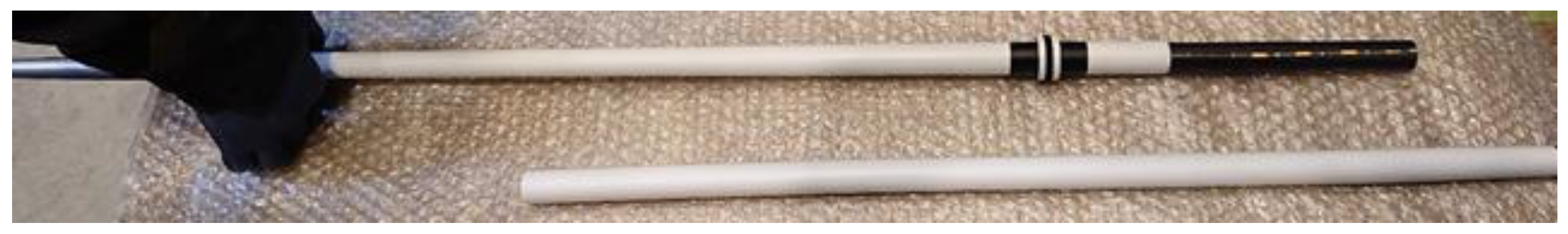
2.1. Javelin
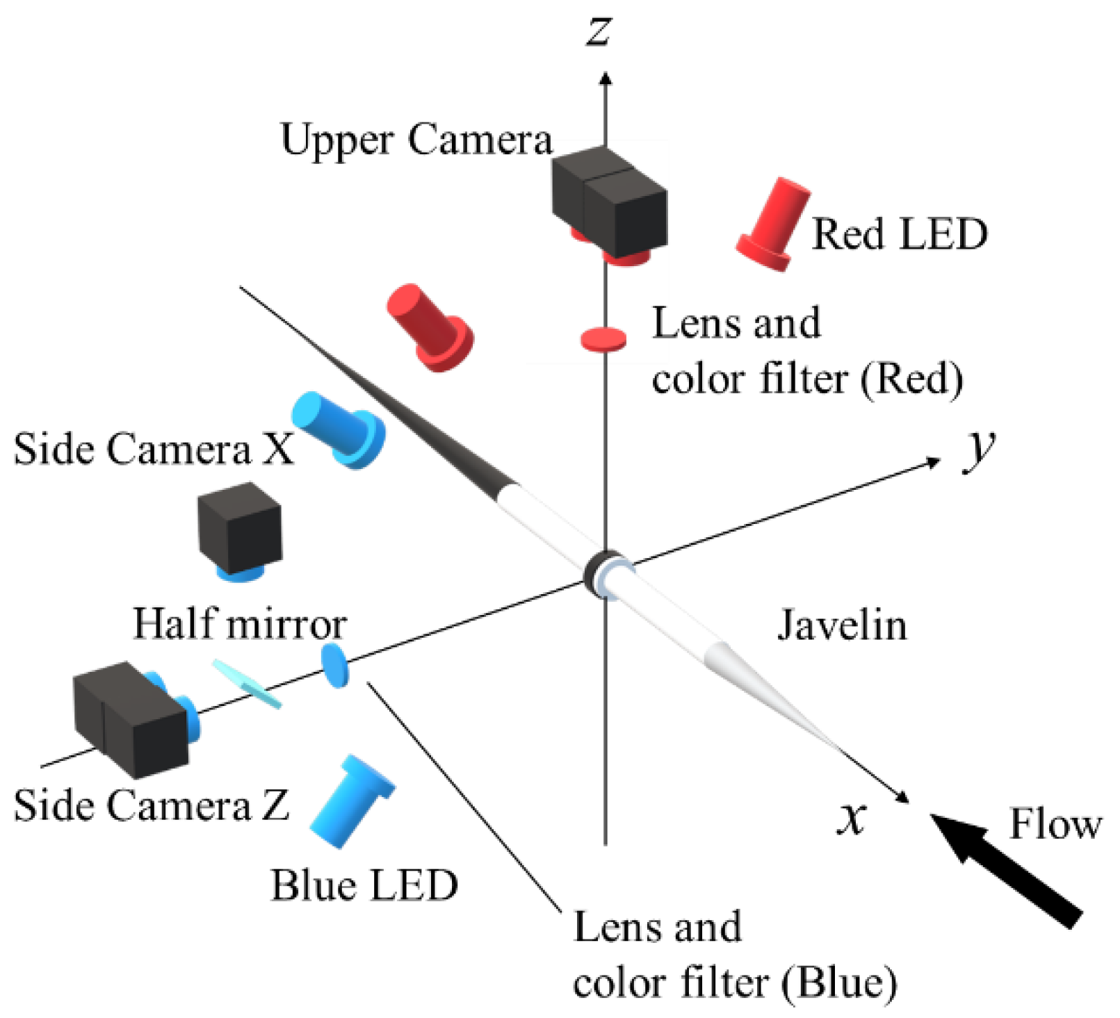
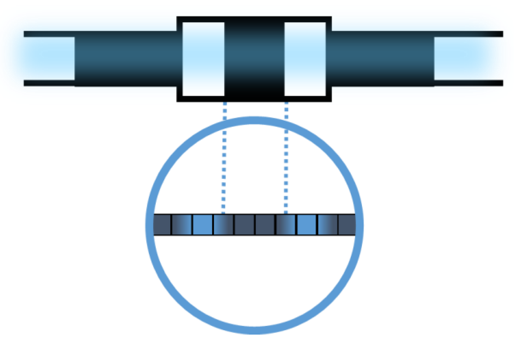
2.2. Position-Sensing System
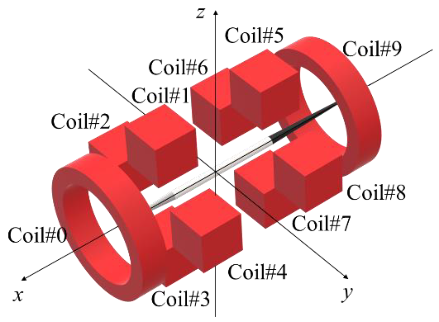
2.3. Coil System
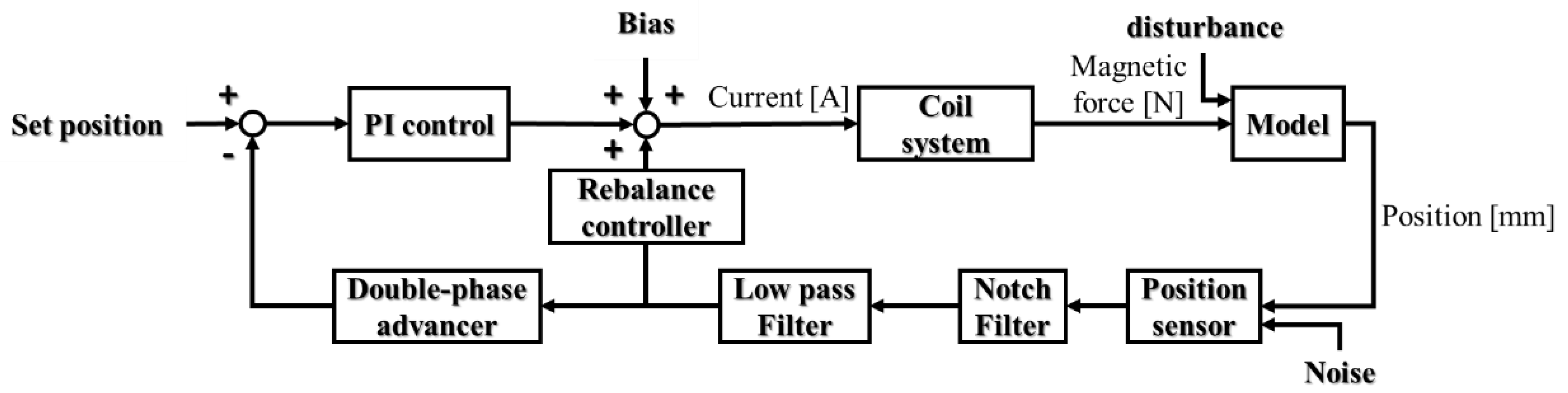
2.4. Control System
2.5. Calibration
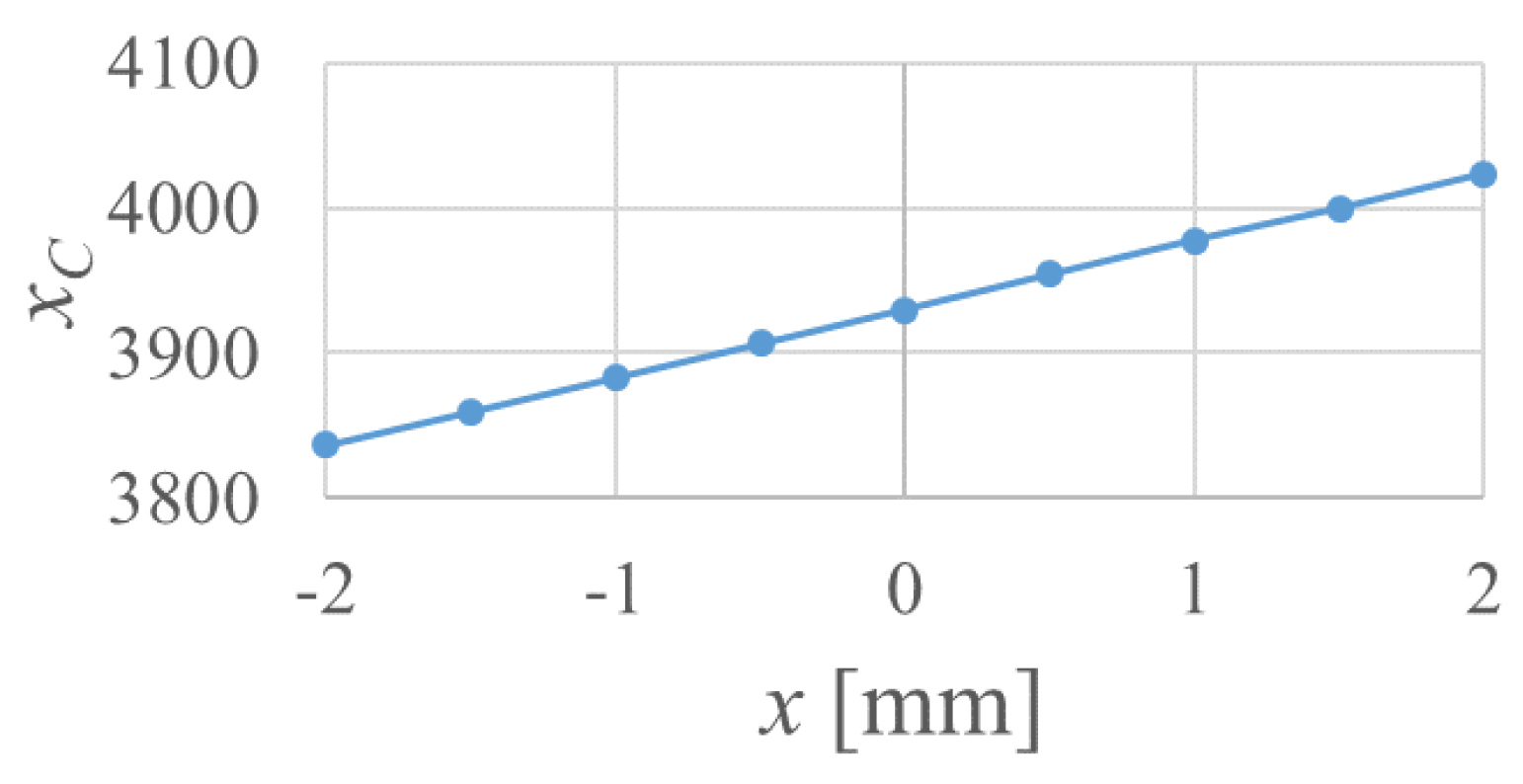
2.5.1. Position-Sensing System
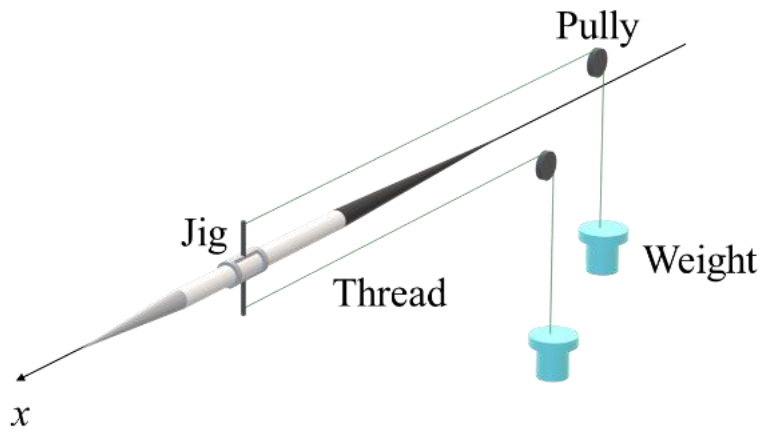
2.5.2. Force Calibration
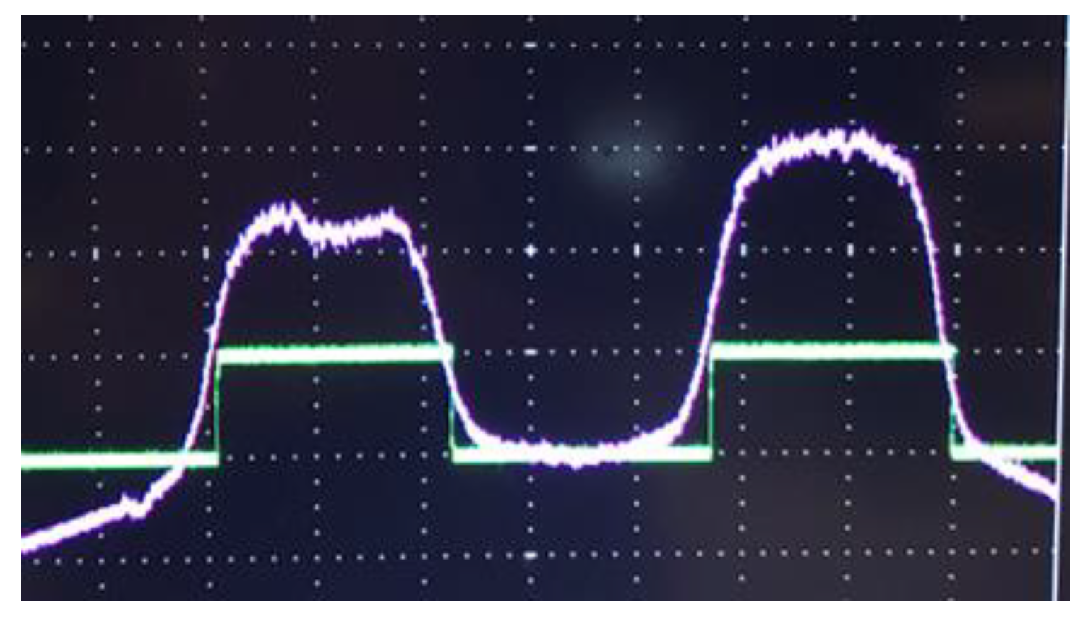
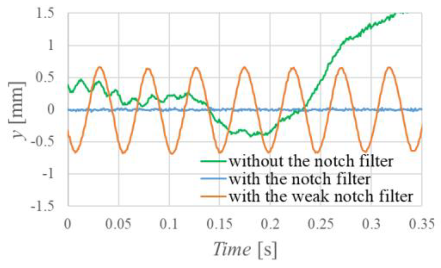
2.6. Filtering the Resonance Frequency
2.7. Experimental Conditions
3. Measurement of Aerodynamic Forces Acting on the Javelin
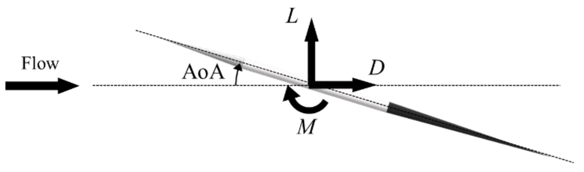
3.1. Aerodynamic Forces Acting on the Javelin
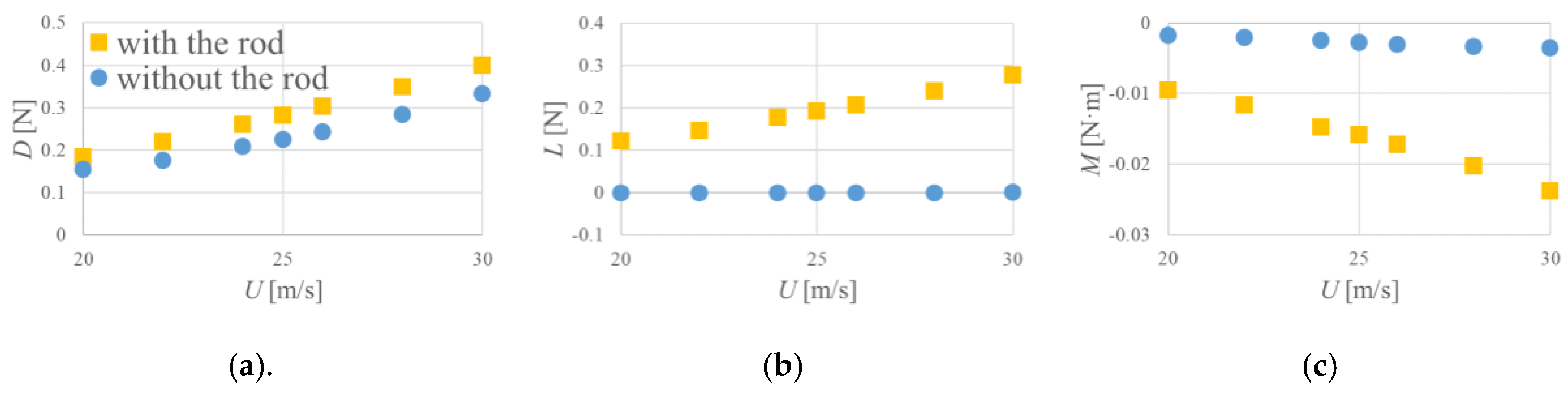
3.2. Interference by the Supporting Rod
4. Summary
- The effect of the resonant frequency of the javelin was nullified by using a notch filter, which allowed the javelin to be levitated stably in the MSBS.
- The drag and the lift coefficients increased with increasing the angle of attack up to 18°.
- The pitching moment coefficient increased with increasing the angle of attack up to about 9°, and then decreased, becoming negative above 12°.
- The drag and the lift coefficients of a javelin oscillating at its resonant frequency were comparable to those of a static javelin.
- The difference in the pitching moment coefficient between the oscillating javelin and the static javelin became significant for angles of attack above 10°.
- There were differences between the drag, the lift, and the pitching moment whether the supporting rod was used or not.
Author Contributions
Funding
Conflicts of Interest
References
- Sawada, H.; Higuchi, H.; Kunimasu, T.; Suda, S. Drag coefficients of cylinders magnetically supported in axial flow. JWE 2004, 29, 55–62. [Google Scholar] [CrossRef]
- Suda, S.; Sawada, H.; Kunimasu, T. Control Constants Decision Method of Proportional-Integral Control and Double Phase Advance for Magnetic Suspension and Balance Systems. JSASS 2005, 53, 97–107. [Google Scholar] [CrossRef]
- Maeda, M.; Nomura, H.; Yanagida, Y. Vibration characteristics of javelin -Effect of the revised rule. J. Phys. Educ. Sports Sci. 1992, 1, 3–10. [Google Scholar]


Publisher’s Note: MDPI stays neutral with regard to jurisdictional claims in published maps and institutional affiliations. |
© 2020 by the authors. Licensee MDPI, Basel, Switzerland. This article is an open access article distributed under the terms and conditions of the Creative Commons Attribution (CC BY) license (https://creativecommons.org/licenses/by/4.0/).
Share and Cite
Kobayashi, T.; Seo, K.; Kaneda, S.; Sasaki, K.; Shinji, K.; Oyama, S.; Okuizumi, H.; Konishi, Y.; Hasegawa, H.; Obayashi, S. Measurement of the Aerodynamic Forces Acting on a Non-Spinning Javelin Using an MSBS. Proceedings 2020, 49, 144. https://doi.org/10.3390/proceedings2020049144
Kobayashi T, Seo K, Kaneda S, Sasaki K, Shinji K, Oyama S, Okuizumi H, Konishi Y, Hasegawa H, Obayashi S. Measurement of the Aerodynamic Forces Acting on a Non-Spinning Javelin Using an MSBS. Proceedings. 2020; 49(1):144. https://doi.org/10.3390/proceedings2020049144
Chicago/Turabian StyleKobayashi, Takuto, Kazuya Seo, Shoya Kaneda, Kasumi Sasaki, Kento Shinji, Shogo Oyama, Hiroyuki Okuizumi, Yasufumi Konishi, Hiroaki Hasegawa, and Shigeru Obayashi. 2020. "Measurement of the Aerodynamic Forces Acting on a Non-Spinning Javelin Using an MSBS" Proceedings 49, no. 1: 144. https://doi.org/10.3390/proceedings2020049144