Proceeding Paper

Dynamic Motion Analysis Using a Wearable Sensor System in a Stabilometer Installed with Generation Function of Disturbance from a Floor †

1
Department of Mechanical Engineering, Doshisha University, 1-3, Tataramiyakodani, Kyotanabe City, Kyoto 610-0321, Japan
2
Faculty of Science and Engineering, Doshisha University, 1-3, Tataramiyakodani, Kyotanabe City, Kyoto 610-0321, Japan
3
Tec Gihan Co., Ltd., 1-22, Nishinohashi, Okubo, Uji City, Kyoto 611-0033, Japan
*
Author to whom correspondence should be addressed.
Presented at the 13th conference of the International Sports Engineering Association, Online, 22–26 June 2020.
Proceedings 2020, 49(1), 164; https://doi.org/10.3390/proceedings2020049164
Published: 15 June 2020

Abstract

:
In this study, we developed an evaluation method using posture and joint torque for the evaluation of balance ability. The evaluation and analysis of standing with a disturbance is conducted for effective balance evaluations. Center of pressure information is mainly used for the evaluation of balance ability using a stabilometer. It is necessary for a more detailed analysis to combine the measurements of body motion. The analysis of posture and joint angle is conducted by body-motion measurement, and joint torque is calculated using ground reaction force and posture information. In this study, we estimated posture and joint torque using a wearable sensor system in the balance evaluation of standing using a stabilometer that generates a disturbance. The analytical results indicated the posture information and joint torque. Analysis and feedback in a short time can be conducted using the wearable sensor system.

1. Introduction

Standing-balance ability is an important factor in sports performance evaluations. Standing-balance ability is evaluated using the center of pressure (COP), measured using a stabilometer. In the previous studies, the static balance was evaluated between a training group and a non-training group [1], and the dynamic balance was evaluated over a wide age range [2]. A stabilometer comprising the function of disturbance generation, such as visual information and movement of the base plate, was developed, and a stabilometer comprising the function of disturbance generation was developed as a device for the evaluation and improvement of balance ability. The stabilometer was used for the analysis of mechanical impedance between the human and the environment, using the function of disturbance generation [3]. The stabilometer is installed with the function of disturbance generation by moving the base plate, and the function is controlled by using the COP information, and the base plate is moved by the coordinate phase or inverse phase of the changes of the COP. Therefore, the stabilometer generates translational acceleration.
A wearable sensor system has been developed as a simple motion measurement device [4]. This system consists of wearable motion sensors and wearable force plates. The wearable motion sensor comprises an inertial sensor and a magnetometer, and the wearable force plate comprises compact force sensors. The body motion and ground reaction force can be measured by using this system, and kinetics and kinematics analysis can be conducted by using the measurement information. It is necessary for these analyses to obtain posture information. Posture can be estimated by applying a sensor fusion algorithm to the inertial sensor and magnetometer outputs [4]. However, the performance of posture estimation declines under conditions of disturbance generation by translational acceleration. Therefore, we used the sensor fusion algorithm avoiding the effects of translational acceleration by focusing on a local coordinate system for the evaluation of the stabilometer installed with the function of disturbance generation by the base plate movement. Furthermore, the calculation of joint torque was conducted using sensor outputs and estimated posture information. Joint torque data are mainly used for the evaluation and analysis of performance analysis of athletes in sports, and the detailed analysis can be used for the evaluation of balance ability using the joint torque data.
In this study, we estimated posture information for the evaluation of balance ability, and we calculated joint torque for detailed analysis. These results were compared with the results that use an optimal motion capture system, and we indicated the effectiveness of this system and the method by using the analysis results.

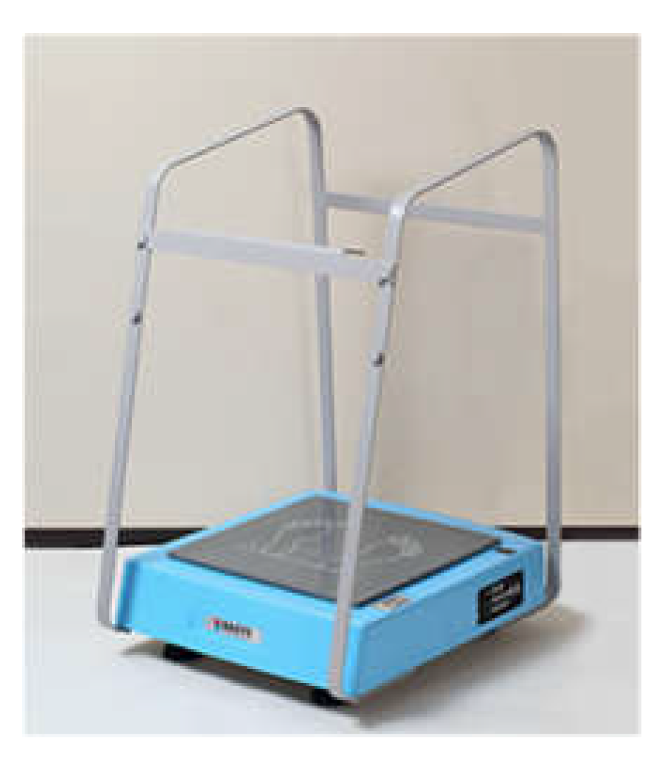
2. Wearable Sensor System

The wearable sensor system (M3D Gait Analysis system, Tec Gihan Co., Ltd., Kyoto, Japan) is shown in Figure 1. This system consists of six wearable motion sensors and four wearable force plates. The wearable force plate is installed with four three-axis compact force sensors, an inertial sensor, and a magnetometer. The force plate outputs 6-axis component forces, COP information, and motion information.

3. Analysis Method

Posture was estimated by sensor fusion and inertial sensor outputs. Most sensor fusion algorithms estimate posture information in global coordinates, and the effect of translational acceleration is compensated for by assuming white noise. However, these algorithms cannot remove the effect of dynamic acceleration. Therefore, we applied the sensor fusion algorithm focusing on a local coordinate system [5]. The sensor fusion estimates the Roll-Pitch-Yaw angles in a local coordinate using either the Extend Kalman filter or the Unscented Kalman filter. In this study, we used the Extended Kalman filter due to the characteristics of the Extended Kalman filter (EKF) that have low computation amount and sufficient sampling frequency. In the standing condition, changes in the Yaw angle are small. Therefore, the Roll and Pitch angles were estimated in this study.
The sensor fusion for estimating the 3D posture is composed of the acceleration and angular velocity of the inertial sensor in the two-link model shown in Figure 2. A nonlinear state equation and a nonlinear measurement equation are developed for the posture estimation. The nonlinear state equation is developed by the relational expression between joint angular velocity and angular velocity and the relational expression between the Roll-Pitch-Yaw angles and joint angular velocity; the nonlinear measurement equation is developed by the relational expression between the acceleration of link i and the one of link i + 1. The accelerations are the sum of translational and gravity acceleration. The relation of joint and link is shown in Figure 2. The relational expression between joint angular velocity and angular velocity is shown in Equation (1), and the relational expression between the Roll and Pitch angles and joint angular velocity is shown in Equation (2), where ωi, ωi+1 are gyro sensor outputs (angular velocity) from link i and link i+1, respectively, iRi+1 is the rotational matrix from link i + 1 to link i, ui = [uix, uiy, uiz]T is joint angular velocity, iφi+1, iθi+1 are the Roll and Pitch angles of link i + 1 in the link i coordinate system. The rotational matrix consists of the Roll and Pitch angles in local coordinates is shown in Equation (3).
The nonlinear measurement equation is developed using the relational expression between the acceleration of link i and the one of link i + 1. The accelerations are the sum of translational and gravity acceleration. The centrifugal and tangential accelerations are calculated using the gyro sensor output and the position vector from the acceleration sensor to the joint. The relational expression between the acceleration of link i and the one of link i + 1 is shown in Equation (4), where Api, Api+1 are acceleration sensor outputs from link i and link i + 1, and Acti, Acti+1 are the sums of centrifugal and tangential accelerations due to rotation of joint i from acceleration sensors of link i and link i + 1. The nonlinear state equation and the nonlinear measurement equation are shown in Equations (5) and (6).
u i + 1 = ω i + 1 R i i + 1 T ω i
[ θ ˙ i i + 1 φ ˙ i i + 1 ] = [ 0 cos φ i i + 1 sin φ i i + 1 1 sin φ i i + 1 tan θ i i + 1 cos φ i i tan θ i i + 1 ] [ u i + 1 x u i + 1 y u i + 1 z ]
R i i + 1 = [ cos θ i i + 1 0 sin θ i i + 1 0 1 0 sin θ i i + 1 0 cos θ i i + 1 ] [ 1 0 0 0 cos φ i i + 1 sin φ i i + 1 0 sin φ i i + 1 cos φ i i + 1 ] = R Y ( θ i i + 1 ) R X ( φ i i + 1 )
A i p + A i c t = R i i + 1 ( A i + 1 p A i + 1 c t )
x ( t ) + 1 = F ( x ( t ) ) + w ( t ) x ( t ) = [ φ i i + 1 θ i i + 1 ] ,   F ( x ( t ) ) = [ φ i i + 1 + ( u i + 1 x + sin φ i i + 1 tan θ i i + 1 u i + 1 y + cos φ i i + 1 tan θ i i + 1 u i + 1 z ) Ts θ i i + 1 + ( cos φ i i + 1 u i + 1 y sin φ i i + 1 u i + 1 z ) Ts ]
y ( t ) = H ( x ( t ) ) + v ( t ) y ( t ) = [ A i p + A i c t A i + 1 p A i + 1 c t ] , H ( x ( t ) ) = [ R i i + 1 ( A i + 1 p A i + 1 c t ) R i i + 1 T ( A i p + A i c t ) ]
The joint torque is calculated by inverse dynamics using the sensor outputs and the estimated posture. The inverse dynamics was conducted by using a method applied in a previous study [6], and the body was assumed to be a rigid link model with four links. The rigid link model is shown in Figure 3.

4. Experimental Conditions

The measurement experiment was conducted on a healthy subject (height: 179 cm, weight: 79 kg, age: 22), using the wearable sensor, the stabilometer installed with the function of disturbance generation (BASYS, Tec Gihan Co. Ltd., Kyoto, Japan), and the optimal motion capture system consisting of seven cameras (VENUS3D, Nobby Tech. Ltd., Tokyo, Japan). The stabilometer is shown in Figure 4, and the stabilometer is installed with an In-phase mode and an Anti-phase mode. The In-phase mode is moved by the base plate of the staiblometer through the coordinate phase of the change in the COP displacement, and the Anti-phase mode is moved by the base plate of the stabilometer through the inverse phase of the change in the COP displacement. Furthermore, the movement amount of the base plate against the COP displacement can be changed. Therefore, the generated amount of translational acceleration in the Anti-phase mode is larger than the one in the In-phase mode. In the experiment, the stabilometer was used in the Anti-phase mode, and the movement amount of the base plate was set to 15%. The sampling frequency was 500 Hz for the wearable sensor system, and the sampling frequency of the optimal motion capture system was 200 Hz. The test subject was a healthy male, the measurement time was 15 s per trial, and the experimental count was 10 times.

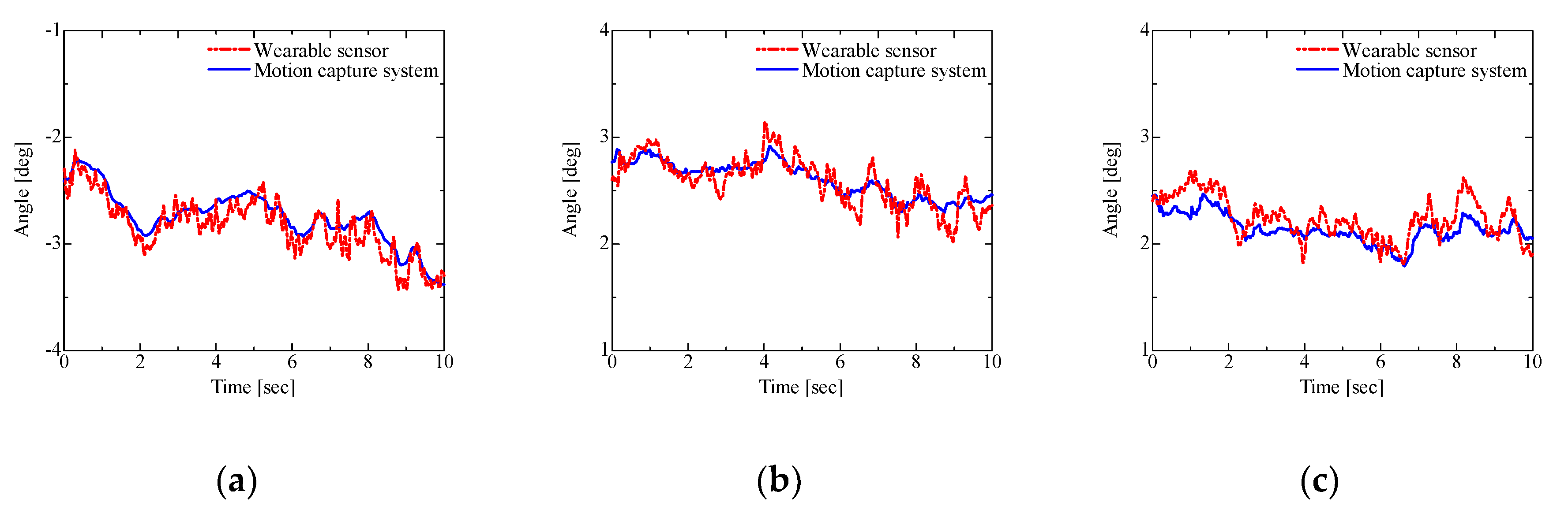
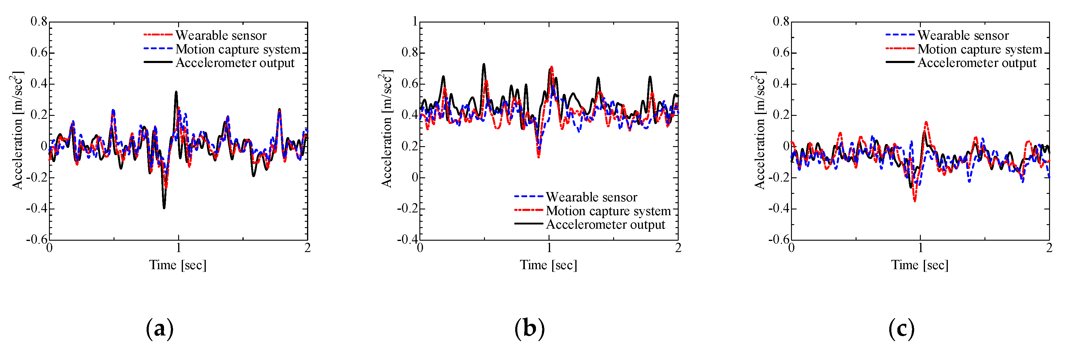
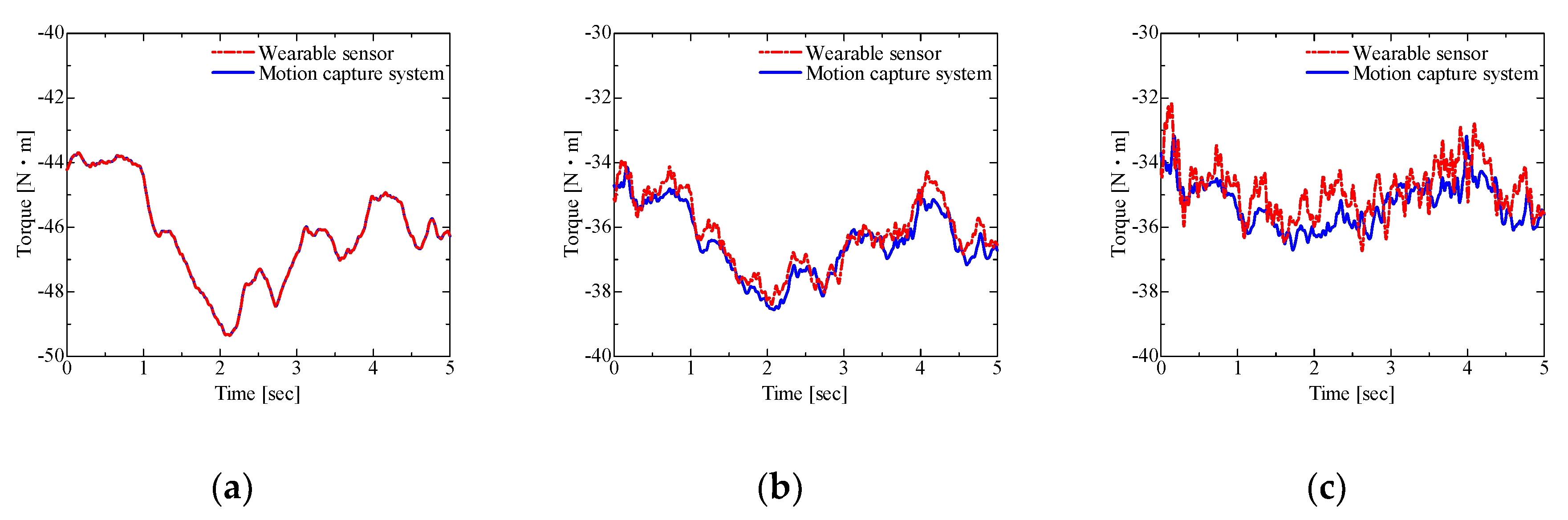
5. Results and Discussion

The results for the joint angles of ankle, knee, and hip joints are shown in Figure 5. These results are a comparison of the joint angles estimated by using the wearable sensor system and the joint angles calculated by the optimal motion capture system. In these results, the joint angles estimated by the wearable sensor system corresponded approximately with the joint angles using the optimal motion capture system. Therefore, the performance of the posture estimation method can be indicated in the evaluation of balance ability. The change in joint angle measured by the wearable sensor system was larger than the one by the optimal motion capture system. These results indicate the possibility of an estimation error in the wearable sensor system and a filtering error in the optimal motion capture. Therefore, we conducted an error analysis using the acceleration between the links. The acceleration of joint in link i + 1 can be calculated by the acceleration, angular velocity, and posture in link i. The expression is shown in Equation (7), where irjoint is the position vector from the accelerometer to the joint in the link i coordinate system.
A i + 1 = R i i + 1 T ( A i + ω i × ω i × r i j o int + ω ˙ i × r i j o int )
The results for the acceleration of the foot joint in the foot coordinate system calculated by using the accelerometer attached to the lower thigh, the acceleration of the knee joint in the lower thigh coordinate system calculated by using the accelerometer attached to the femur, and the acceleration of the hip joint in the femur coordinate system calculated by using the accelerometer attached to the lumbar are shown in Figure 6. These results were compared with the acceleration calculated using a second differential of the reactive marker position and the accelerometer outputs. The results for acceleration from the wearable sensor agreed approximately with the one from the accelerometer outputs. However, the results for acceleration from the motion capture system did not agree with the results for acceleration from accelerometer outputs. The RMSEs (Root mean square errors) from the wearable sensor system were 0.072 m/s2 (ankle joint), 0.090 m/s2 (knee joint), and 0.066 m/s2 (hip joint), and the ones in the optimal motion capture system were 0.095 m/s2 (ankle joint), 0.103 m/s2 (knee joint), and 0.089 m/s2 (hip joint). These results indicate the potential for detailed behavior changes using the wearable sensor system.
The results for the joint torque were calculated using the wearable sensor system and the motion capture system by applying the method of previous study [7]. The results for joint torque are shown in Figure 7. The results from the wearable sensor system were noisy. However, the estimated joint torque using the wearable sensor system indicated the results agree approximately with the joint torque using the motion capture system.

6. Conclusions

In this study, we established the estimation of posture and joint torque for the evaluation of balance ability. The estimated joint angles indicated performance agreeing with the results of a motion capture system. Furthermore, we conducted error analysis using the acceleration, valid results were indicated, and the calculated joint torque also indicated the validity of the results. The posture estimation and the calculation of joint angles can be conducted in a short time. The change of joint angles and torque in this experiment were small due to conduct by a healthy subject. However, the wearable sensor system and the method can indicate the characteristics of motion. Therefore, the method using the wearable sensor system can be used to give immediate feedback on balance evaluation in sports and rehabilitation.

References

  1. Fujiwara, K.; Ikegami, Y. A Study on the Relationship between the Position of the Center of Foot Pressure and the Steadiness of Standing Posture. Jpn. Soc. Phys. Educ. 1981, 26, 137–147. [Google Scholar]
  2. Suzuki, Y.; Nakata, Y.; Kato, H.; Tanabe, Y.; Iwabuchi, S.; Ishikawa, K. Association between age and dynamic balance capability assessed by use of force plates. Jpn. J. Phys. Fit. Sports Med. 2015, 64, 419–425. [Google Scholar]
  3. Murai, A. Impendance model of the interactoin between environment and human body and its modification design. In Proceedings of the 40th Annual International Conference of the IEEE Engineering in Medicine and Biology Society (EMBC-40), Honolulu, HI, USA, 17–21 July 2018; pp. 1805–1808. [Google Scholar]
  4. Adachi, W.; Tsujiuchi, N.; Koizumi, T.; Shiojima, K.; Tsuchiya, Y.; Inoue, Y. Development of Walking Analysis System Using by Motion Sensor with Mobile Force Plate. J. Syst. Des. Dyn. 2012, 6, 655–664. [Google Scholar]
  5. Hirose, K.; Doki, H.; Kondo, A. Studies on Orientation Measurement in Sports Using Inertial and Magnetic Field Sensors. J. Jpn. Soc. Sports Ind. 2012, 22, 255–262. (In Japanese) [Google Scholar] [CrossRef]
  6. Kondo, A.; Doki, H.; Hirose, K. A study on the estimation method of 3D posture in body motion measurement using inertial sensors. Trans. Jpn. Soc. Mech. Eng. Ser. C 2013, 79, 2351–2361. (In Japanese) [Google Scholar] [CrossRef]
  7. Hirose, K.; Doki, H.; Kondo, A. Dynamic analysis and motion measurement of ski turns using inertial and force sensors. Procedia Eng. 2013, 60, 355–360. [Google Scholar] [CrossRef]
Figure 1. Mounting positions of the wearable sensor system; (a) Wearable motion sensor; (b) Wearable force plate.
Proceedings 49 00164 g001
Figure 2. Two-link model for estimation of posture in local coordinates.
Proceedings 49 00164 g002
Figure 3. Rigid link model.
Proceedings 49 00164 g003
Figure 4. Stabilometer installed with the function of disturbance generation (BASYS).
Proceedings 49 00164 g004
Figure 5. Results for joint angle estimated using the wearable sensor and obtained by the motion capture system; (a) Ankle joint angle; (b) Knee joint angle; (c) Hip joint angle.
Proceedings 49 00164 g005
Figure 6. Results for acceleration calculated using the wearable sensor, the motion capture system, and the accelerometer outputs; (a) Acceleration of the ankle joint from the wearable sensor attached to the lower thigh; (b) Acceleration of the knee joint from the wearable sensor attached to the femur; (c) Acceleration of the hip joint from the wearable sensor attached to the lumbar.
Proceedings 49 00164 g006
Figure 7. Results for joint torque from the wearable sensor and the motion capture system; (a) Ankle joint torque; (b) Knee joint torque; (c) Hip joint torque.
Proceedings 49 00164 g007
Publisher’s Note: MDPI stays neutral with regard to jurisdictional claims in published maps and institutional affiliations.

