Biomimetic Design of a Planar Torsional Spring to an Active Knee Prosthesis Actuator Using FEM Analysis †

 , and
, and
Abstract
:1. Introduction
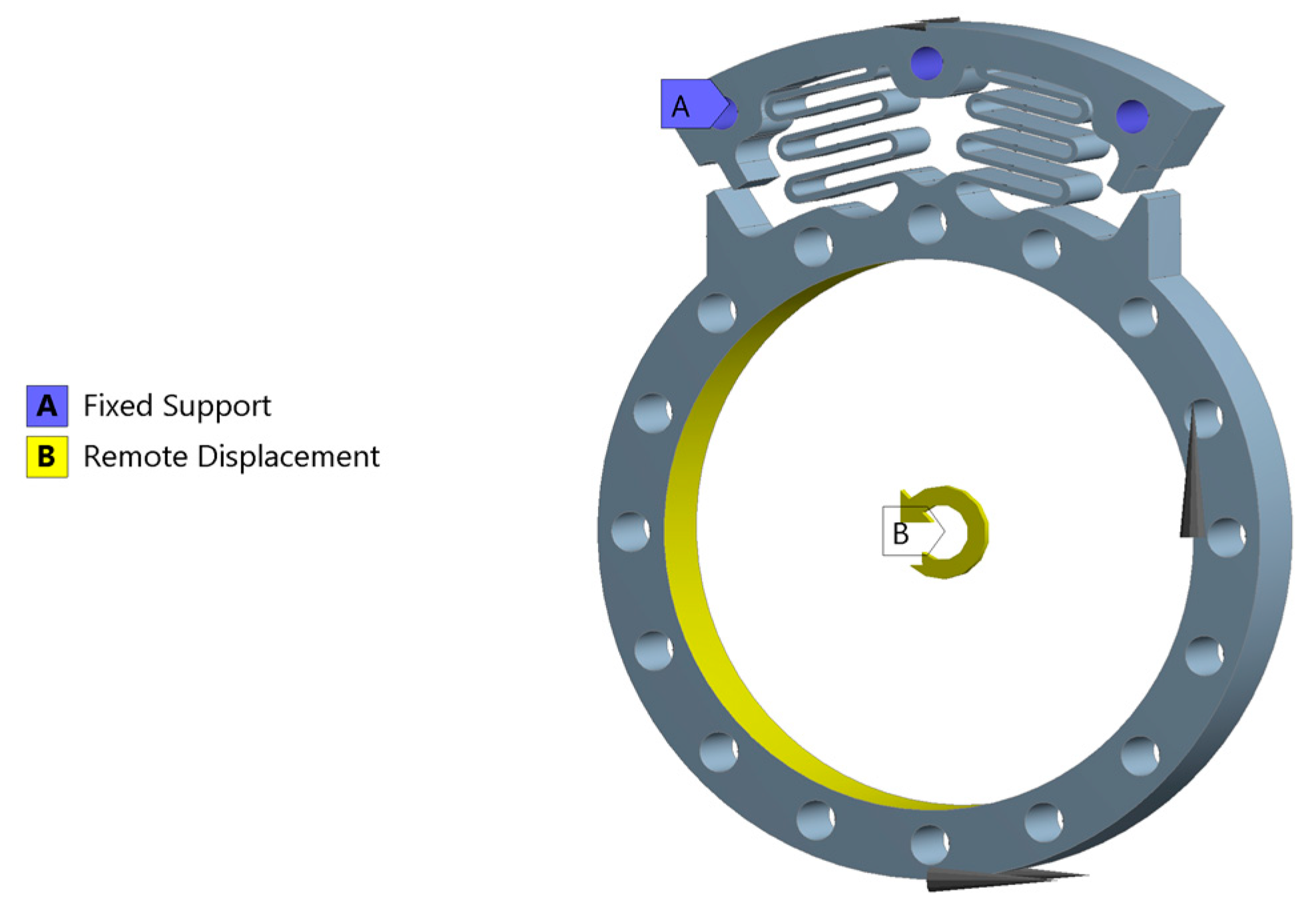
2. Mechanical Design
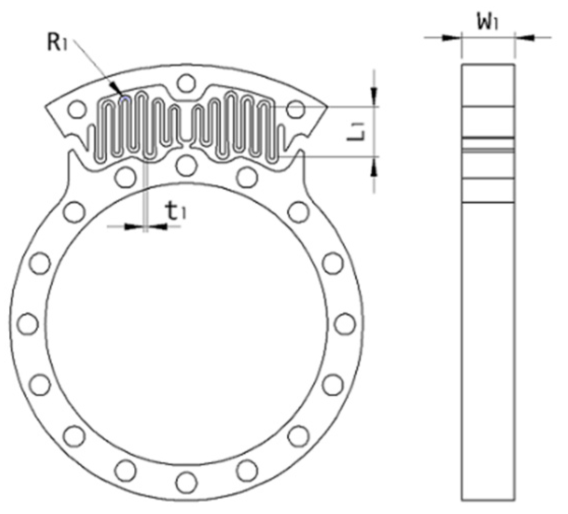
Spring Design
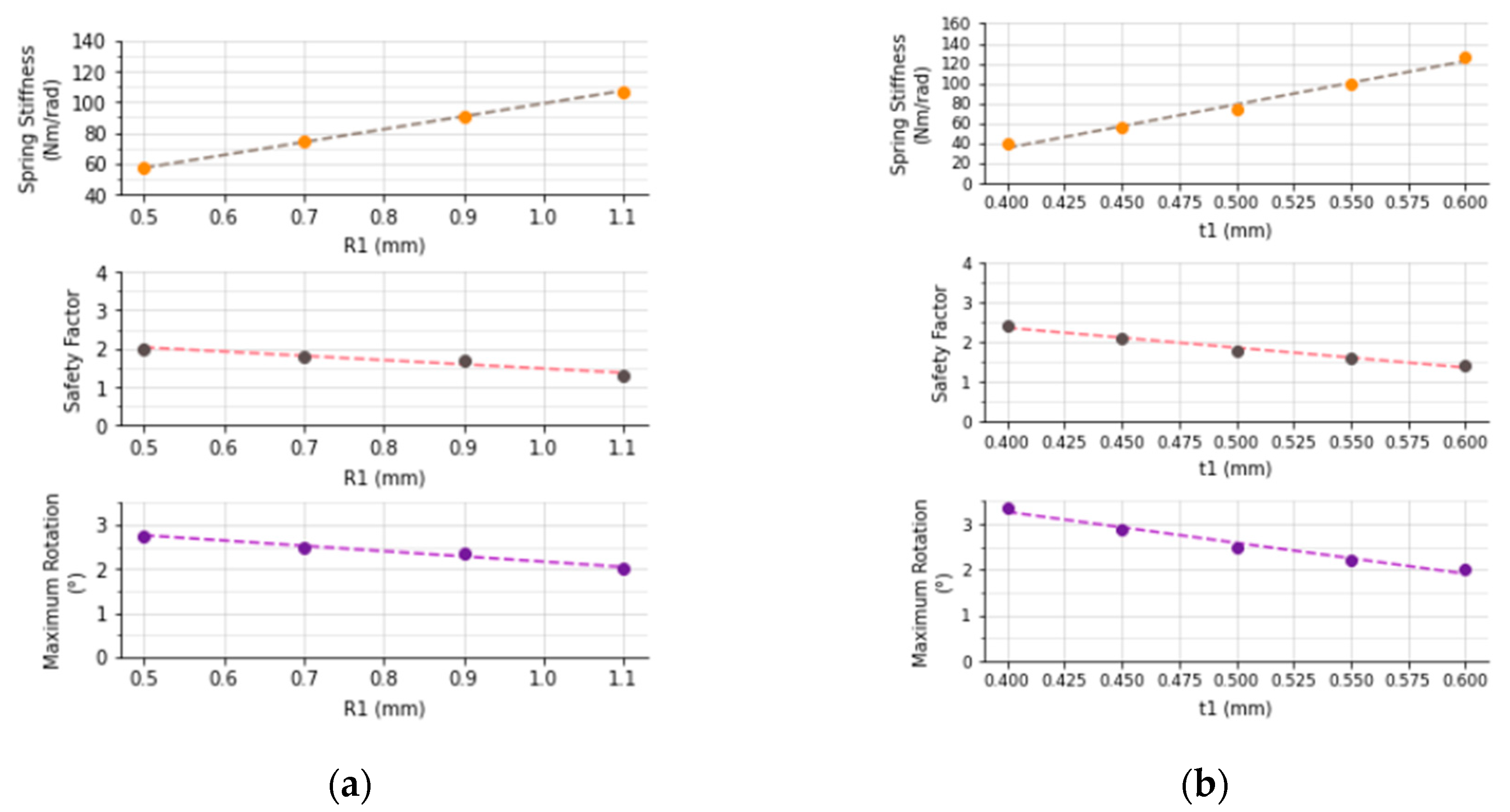
3. Results
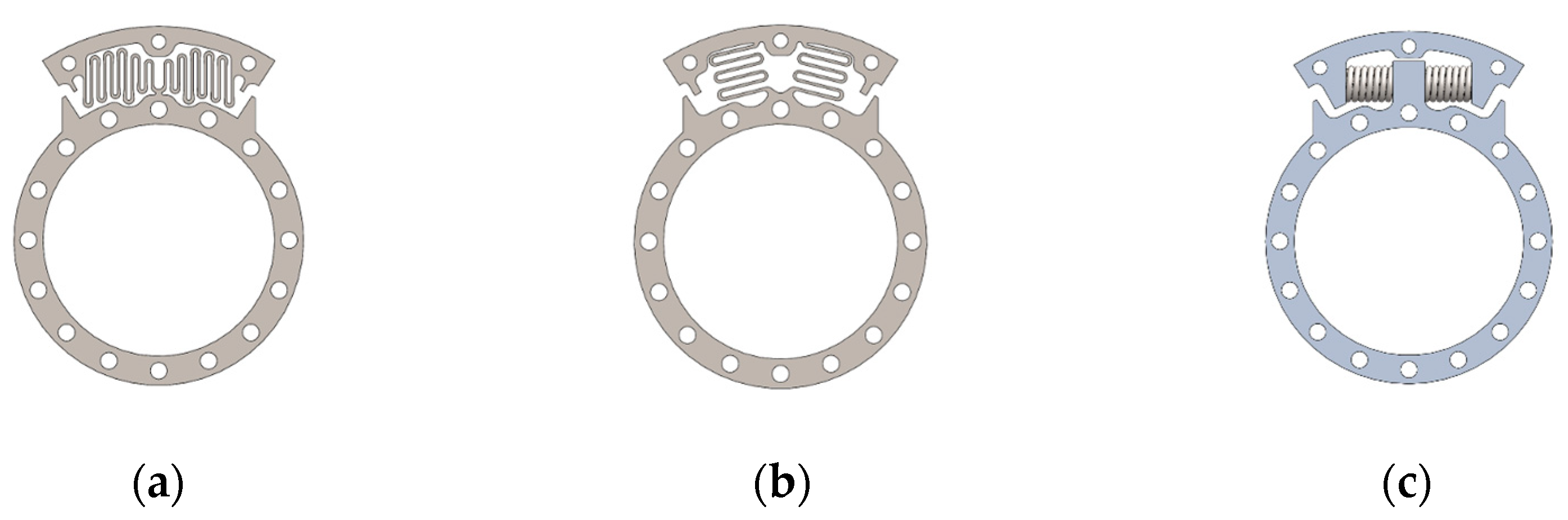
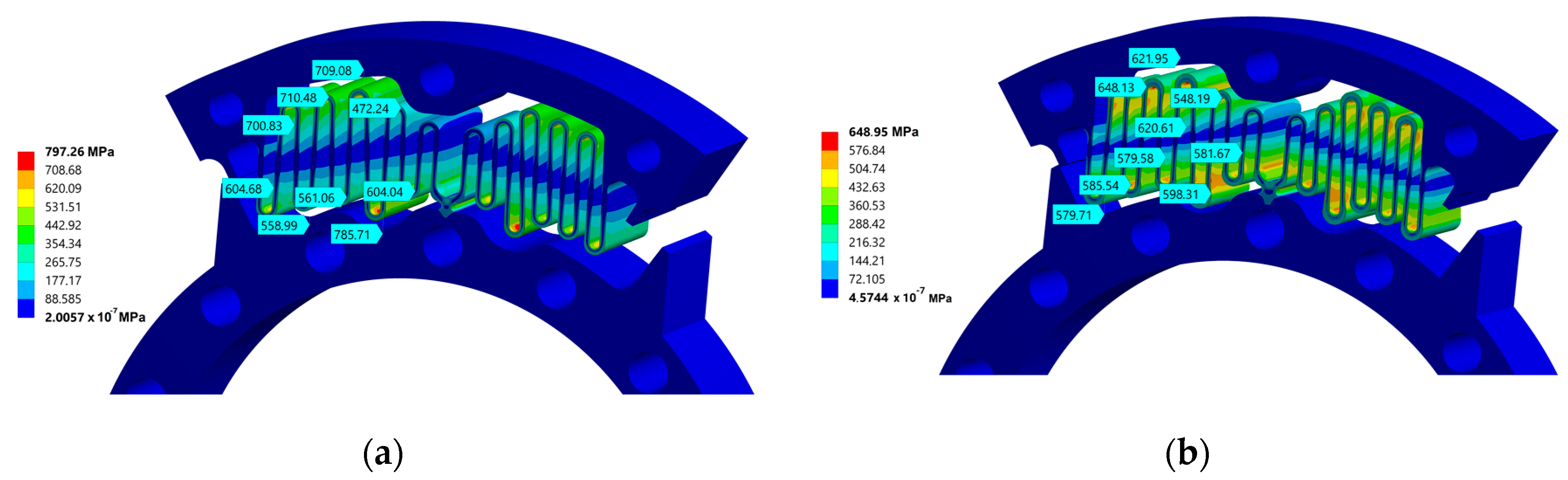
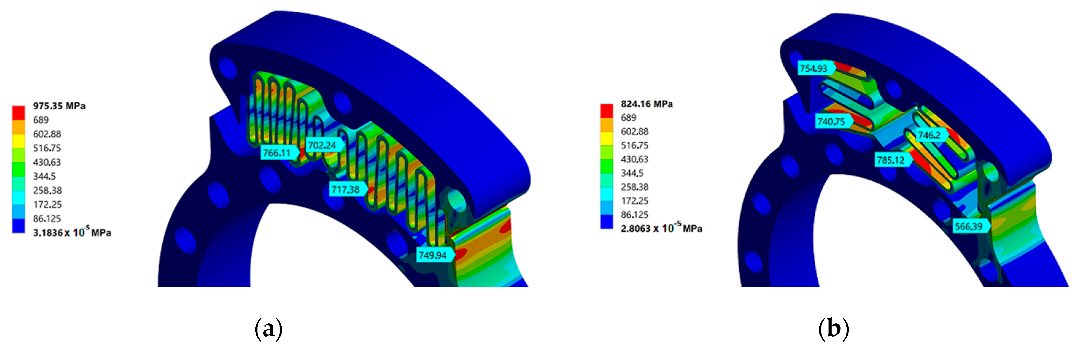
3.1. First Design
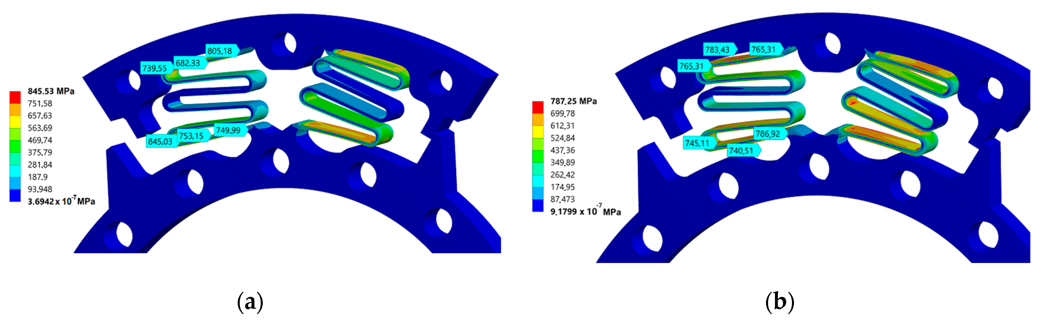
3.2. Second Design
3.3. Third Design
3.4. Mechanical End Stop
4. Discussion
5. Conclusions
Author Contributions
Acknowledgments
Conflicts of Interest
Abbreviations
| CAD | Computer Aided Design |
| FEM | Finite Element Method |
| MDPI | Multidisciplinary Digital Publishing Institute |
| SEA | Series Elastic Actuator |
References
- DATASUS. Informações de Saúde. Procedimentos Hospitalares do SUS. Available online: http://tabnet.datasus.gov.br/cgi/deftohtm.exe?sih/cnv/piuf.def (accessed on 10 July 2020).
- Andrade, R.M. Joelho Magneto-Reológico Para Próteses Transfemurais: Prototipagem Digital, Fabricação e Identificação Experimental. Ph.D. Thesis, Universidade Federal de Minas Gerais, Belo Horizonte, Brazil, 2018. [Google Scholar]
- Rouse, E.J.; Mooney, L.M.; Herr, H.M. Clutchable series-elastic actuator: Implications for prosthetic knee design. Int. J. Robot. Res. 2014, 33, 1611–1625. [Google Scholar] [CrossRef]
- Fanciullacci, C.; McKinney, Z.; Monaco, V.; Milandri, G.; Davalli, A.; Sacchetti, R.; Paternò, L. Evaluation of Human Factors for the User-centered Design of Powered Robotic Transfemoral Prostheses: A Survey of Transfemoral Amputee Experience and Priorities. J. Neuroeng. Rehabil. 2020. Available online: https://www.researchsquare.com/article/rs-68433/v1 (accessed on 10 July 2020). [CrossRef]
- Andrade, R.M.; Filho, A.B.; Vimieiro, C.B.S.; Pinotti, M. Optimal design and torque control of an active magnetorheological prosthetic knee. Smart Mater. Struct. 2018, 27, 105031. [Google Scholar] [CrossRef]
- Leal junior, A.G.; Andrade, R.M.; Filho, A.B. Series Elastic Actuator: Design, Analysis and Comparison. Recent Adv. Robot. Syst. 2016, 1, 203–234. Available online: https://www.intechopen.com/books/recent-advances-in-robotic-systems/series-elastic-actuator-design-analysis-and-comparison (accessed on 13 March 2020). [CrossRef]
- Andrade, R.M.; Filho, A.B.; Vimieiro, C.B.S.; Pinotti, M. Evaluating Energy Consumption of an Active Magnetorheological Knee Prosthesis. In Proceedings of the 19th International Conference on Advanced Robotics (ICAR), Belo Horizonte, Brazil, 2–6 December 2019; pp. 75–80. [Google Scholar] [CrossRef]
- Tsagarakis, N.G.; Laffranchi, M.; Vanderborght, B.; Caldwell, D.G. A compact soft actuator unit for small scale human friendly robots. IEEE Int. Conf. Robot. Autom. 2009, 4356–4362. Available online: https://ieeexplore.ieee.org/document/5152496 (accessed on 4 October 2020). [CrossRef]
- Carpino, G.; Accoto, D.; Sergi, F.; Tagliamonte, N.; Guglielmelli, E. A Novel Compact Torsional Spring for Series Elastic Actuators for Assistive Wearable Robots. J. Mech. Des. 2012, 134, 1–10. Available online: https://www.researchgate.net/publication/234154327_A_Novel_Compact_Torsional_Spring_for_Series_Elastic_Actuators_for_Assistive_Wearable_Robots (accessed on 7 September 2020). [CrossRef]
- Shamaei, K.; Sawicki, G.S.; Dollar, A.M. Estimation of quasi-stiffness of the human knee in the stance phase of walking. PLoS ONE 2013, 8, e59993. Available online: https://www.researchgate.net/publication/236085195_Estimation_of_Quasi-Stiffness_of_the_Human_Hip_in_the_Stance_Phase_of_Walking (accessed on 1 July 2020). [CrossRef] [PubMed]
- Wang, Y.; Chen, Y.; Chen, K.; Wu, Y.; Huang, Y. A flat torsional spring with corrugated flexible units for series elastic actuators. In Proceedings of the 2nd International Conference on Advanced Robotics and Mechatronics (ICARM), Hefei, China, 27–31 August 2017; pp. 138–143. Available online: https://ieeexplore.ieee.org/document/8273149 (accessed on 27 June 2020). [CrossRef]
- Irhke, C.A.; Parsons, A.H.; Mehling, J.S.; Griffith, B.K. Planar Torsion Spring. United States Patent Application Publication No. US 2010/0145510 A1, 10 June 2010. Available online: https://patents.google.com/patent/US20100145510A1/en (accessed on 7 October 2020).
- Doan, T.D. A Novel Torsional Spring Design for Knee Prostheses and Exoskeletons. Bachelor’s Thesis, Massachusetts Institute of Technology, Department of Mechanical Engineering, Cambridge, MA, USA, 2015. [Google Scholar]
- Dos Santos, W.M.; Caurin, G.A.P.; Siqueira, A.A.G. Design and control of an active knee orthosis driven by a rotary Series Elastic Actuator. Control Eng. Pract. 2015. Available online: http://dx.doi.org/10.1016/j.conengprac.2015.09.008 (accessed on 14 August 2020).
- IBGE. Pesquisa de Orçamentos Familiares: Tabela 2645—Estimativas Populacionais das Medianas de Altura e Peso de Crianças, Adolescentes e Adultos, por Sexo, Situação do Domicílio e Idade—Brasil e Grandes Regiões. 2010. Available online: https://sidra.ibge.gov.br/tabela/2645 (accessed on 13 May 2020).
- Andrade, R.M.; Sapienza, S.; Bonato, P. Development of a ‘transparent operation mode’ for a lower-limb exoskeleton designed for children with cerebral palsy. In Proceedings of the IEEE 16th International Conference on Rehabilitation Robotics (ICORR), Toronto, ON, Canada, 24 June 2019; pp. 512–517. [Google Scholar] [CrossRef]
- Boardman, B. Fatigue Resistance of Steels. In Properties and Selection: Irons, Steels, and High-Performance Alloys; ASM International: Almere, The Netherland, 1990; Volume 1, pp. 673–688. [Google Scholar]
- Tartaglia, J.M.; Hayrynen, K.L. A Comparison of Fatigue Properties of Austempered Versus Quenched and Tempered 4340 Steel. J. Mater. Eng Perform 2012, 21, 1008–1024. Available online: https://doi.org/10.1007/s11665-011-9951-y (accessed on 6 October 2020).
- MATWEB. Material Property Data. Available online: http://www.matweb.com/ (accessed on 6 October 2020).


| Alloy Steel | Elasticity Modulus | Poisson’s Ratio | Tensile Yield Strength | Tensile Ultimate Strength |
|---|---|---|---|---|
| AISI 4340 1,2 | 212 GPa | 0.30 | 1475 MPa | 1595 MPa |
| AISI 6150 1 | 205 GPa | 0.29 | 1225 MPa | 1240 MPa |
| External Diameter | Undeflected Length | Maximum Deflection | Stiffness (ka) | |
|---|---|---|---|---|
| Spring 1 | 8.1 mm | 17.5 mm | 7.3 mm | 16.81 N/mm |
| Spring 2 | 8.1 mm | 12.2 mm | 4.7 mm | 26.43 N/mm |
| Parameters | First Design | Second Design | Third Design |
|---|---|---|---|
| W1 | 9 mm | 8.5 mm | 8.1 mm |
| No. of springs | 2 | 2 | 2 |
| Max. rotation | 3.20° | 2.50° | 3.96° |
| Spring Mass | 0.167 kg | 0.153 kg | 0.066 kg |
| Spring Stiffness | 191 N.m/rad | 250 N.m/rad | 122 N.m/rad |
Publisher’s Note: MDPI stays neutral with regard to jurisdictional claims in published maps and institutional affiliations. |
© 2020 by the authors. Licensee MDPI, Basel, Switzerland. This article is an open access article distributed under the terms and conditions of the Creative Commons Attribution (CC BY) license (https://creativecommons.org/licenses/by/4.0/).
Share and Cite
Fiorezi, G.G.; Moraes, J.d.S.d.; Ulhoa, P.H.F.; Andrade, R.M.d. Biomimetic Design of a Planar Torsional Spring to an Active Knee Prosthesis Actuator Using FEM Analysis. Proceedings 2020, 64, 30. https://doi.org/10.3390/IeCAT2020-08505
Fiorezi GG, Moraes JdSd, Ulhoa PHF, Andrade RMd. Biomimetic Design of a Planar Torsional Spring to an Active Knee Prosthesis Actuator Using FEM Analysis. Proceedings. 2020; 64(1):30. https://doi.org/10.3390/IeCAT2020-08505
Chicago/Turabian StyleFiorezi, Guilherme Gomes, Jhonata dos Santos de Moraes, Pedro Henrique Fabriz Ulhoa, and Rafhael Milanezi de Andrade. 2020. "Biomimetic Design of a Planar Torsional Spring to an Active Knee Prosthesis Actuator Using FEM Analysis" Proceedings 64, no. 1: 30. https://doi.org/10.3390/IeCAT2020-08505