A Low-Cost Miniature Electrohydrostatic Actuator †


Department of Mechanical Engineering, University of Saskatchewan, Saskatoon, SK S7N 5A9, Canada
*
Author to whom correspondence should be addressed.
†
Presented at the First International Electronic Conference on Actuator Technology: Materials, Devices and Applications, 23–27 November 2020; Available online: https://iecat2020.sciforum.net/.
Proceedings 2020, 64(1), 35; https://doi.org/10.3390/IeCAT2020-08488
Published: 20 November 2020
(This article belongs to the Proceedings of The 1st International Electronic Conference on Actuator Technology: Materials, Devices and Applications)
Abstract
:This paper presents a low-cost, small-scale, electrohydrostatic actuator (EHA). This actuator leverages low-cost, mass-produced hydraulic components from the radio-controlled model industry, combined with a novel 3D printed valve. The system is capable of relatively high bandwidth operation, with much higher power- and force-density than comparable electrical actuators. This paper presents a dynamic system model, investigating the range of stability.
1. Introduction
There has been much recent research in the field of pump-controlled hydraulic actuators, also known as electrohydrostatic actuators (EHA) (see [1] for a recent review). These actuators promise higher efficiencies than valve-controlled actuators (with their associated losses across throttling valves). They can also offer advantages from a control point of view due to their linearity and load insensitivity. One configuration uses a variable-speed motor coupled to a fixed displacement pump (often a gear pump). If this is used to drive a single-rod cylinder, some facility for balancing the asymmetric flows must be included [2,3,4,5,6,7,8].
These actuators have commercial acceptance in the high power range, including current use for flight-control surfaces on Airbus A380 aircraft [9]. Commercial EHA units are available from a number of manufacturers [10].
In the small actuator range (i.e., displacements on the order of 50 mm and force capacity on the order of 50 N) electrical screw-driven actuators are common [11]. However, these actuators suffer from low force and power density, and high friction.
In recent years, small-scale hydraulic systems have become available, driven by radio-controlled model equipment (some would say “toys”). These systems feature small hydraulic cylinders driven by gear pumps driven by variable speed brushless DC or permanent magnet motors. The system is usually valve-controlled with the pump running at constant speed over a relief valve, resulting in an inefficient and load-sensitive circuit. This paper presents the application of these low-cost components in an EHA configuration. Previously, the lack of a suitable flow-balancing system made these systems economically impractical, so the major contribution of this project is a low-cost flow-balancing valve.
2. Materials and Methods
2.1. System Description
The prototype system is shown in Figure 1 and the schematic in Figure 2. The fixed displacement gear pump is driven by a variable-speed electric motor, in this case a permanent-magnet motor (commonly referred to as brushless DC, or BLDC). The pump and motor were purchased as a matched set, with a rated pressure of 4.5 MPa. For research purposes we drove the motor using an ODrive 24 V motor controller [12], but this could be easily replaced with a low-cost BLDC electronic speed-control (ESC) unit.
A commercially purchased hydraulic cylinder was used as the actuator, with 10 mm bore diameter, 4 mm rod diameter and 50 mm stroke. This cylinder was provided without a technical datasheet, but appears to have a hard, low-friction piston seal (perhaps polytetrafluoroethylene, PTFE) and has a soft elastomeric rod seal, likely nitrile rubber.
The single asymmetric hydraulic cylinder’s unbalanced flow is handled by the inverse shuttle valve, shown in Figure 3. This valve connects the cylinder port with the lower pressure to the low-pressure supply. For testing purposes, this low pressure was supplied by an external pump, but it is believed that it would be possible for this to be replaced with a reservoir or accumulator [13]. The valve casing was 3D-printed from polyethylene terephthalate glycol-modified (PETG) using a Prusa i3 mk3 fused filament printer, at a layer height of 0.10 mm and 100% infill. The casing was produced with optional pressure transducers forming end caps, threaded into printed threads. The captured spool was printed in place, a layout that cannot be realized without using additive manufacturing. The authors believe this is the first hydraulic valve to require neither assembly nor finish machining. This design uses two connected hemispherical poppets that seat into conical seats. The hemispherical shape allows for good sealing even with angular misalignment of the unguided poppet. Once designed, the cost to produce this valve is nearly negligible, with a material cost of less than US$ 1 and requiring less than 4 hours of unattended printing time. For those without access to a 3D printer, numerous commercial enterprises can produce this part at minimal cost. We received commercial quotes for single quantities as low as US$ 13 plus shipping and less than US$ 2 in bulk quantities.
All connecting lines are nylon tubing, rated for 4 MPa, which sets the safe working pressure of the system. Rather than physical relief valves to enforce this pressure limit, we used the measured pressure to limit the pump velocity for this prototype. This system is not entirely reliable, so rupture discs or other weak points could be included in a production version to ensure safety. Alternatively, the motor current could be limited in order to limit pressure if pressure measurement was not required.
A previous paper [13] evaluated the steady state performance of the system and found it to have a very high specific force and power when compared to electrical actuators.
2.2. Dynamic Model
This section presents a dynamic model for the system, using nomenclature shown in Figure 2.
Starting at the load, a force balance on the piston and attached mass gives
where and are the piston areas on the head and rod end, is the externally applied force, is the actuator velocity and, following an equation modified from [14], the effective friction force is given by
where is the Coulomb Friction, is the dynamic viscosity, is a pressure-dependent friction term, is a viscous damping term and is a scale for “small” velocities (this tanh term is used to avoid numerical instability around zero velocity). Fluid friction in lines and fittings is also lumped into (which should have a small effect). We investigated including a turbulent friction term (proportional to but found its value to be statistically indistinguishable from zero in experimental tests. Likewise, a friction term was considered but was also indistinguishable from zero, likely due to the hard piston seal, as compared to the deformable elastomeric rod gland seal.
Assuming constant effective bulk modulus, , in the fluid and containing passageways, continuity requires
where and are the effective compliant volumes (including valve bodies, lines, and piston chambers).
The shuttle valve spool is assumed to have laminar friction and flow forces are neglected, giving a force balance of
where is the spool’s mass, is the symmetrical piston area, and is the damping coefficient. The minimum and maximum displacement are limited by and .
This model lumps all internal leakage (i.e., pump, valve, and cylinder) into and all external leakage and valve flow into and . Laminar internal leakage is given by
where is the leakage resistance. The external leakage and valve flows are given by
where and are the resistances, with conductances linearly varying with spool position
where and are the leakage resistances with the valve closed, and and are the resistances when fully open (including both valve orifices and passageway resistances). While the orifices are likely turbulent at partial opening, the fast-responding valve spends the vast majority of its time at either extreme where the resistance is either dominated by laminar leakage flow or laminar pipe flow. The intermediate resistances are largely included as a convenience for the numerical solver and have little effect on the system dynamics.
2.3. Controller
This section presents an open-loop velocity controller for the system. This is intended to be a minimum viable controller, intended to provide an indication of the stability and controllability of the system, rather than an optimized controller that would actually be used in practice.
First, the controller estimates the valve spool state, either in mode 1 () or mode 2 (). In the ideal case this is simply
More complex realistic controllers would apply filters and/or hysteresis to prevent spurious mode switching due to measurement noise.
Based on the mode, the flow required to achieve the desired velocity, , is calculated, assuming no leakage:
As the leakage is dependent on the measured pressures and , a practical controller could improve steady state accuracy by compensating for this leakage.
2.4. Simulation Studies
The above system of equations was implemented in Matlab Simulink. A input of was applied and the system was allowed to reach steady state. A step in reference velocity was then applied and the actuator velocity and pressures were recorded for a constant load force .
3. Results
4. Discussion
As seen in Figure 4, the dynamic response is generally fast, and oscillations settle quickly. The nonlinear nature of the system can be observed as the velocity response’s shape changes with operating point, with some responses overdamped and others showing some overshoot.
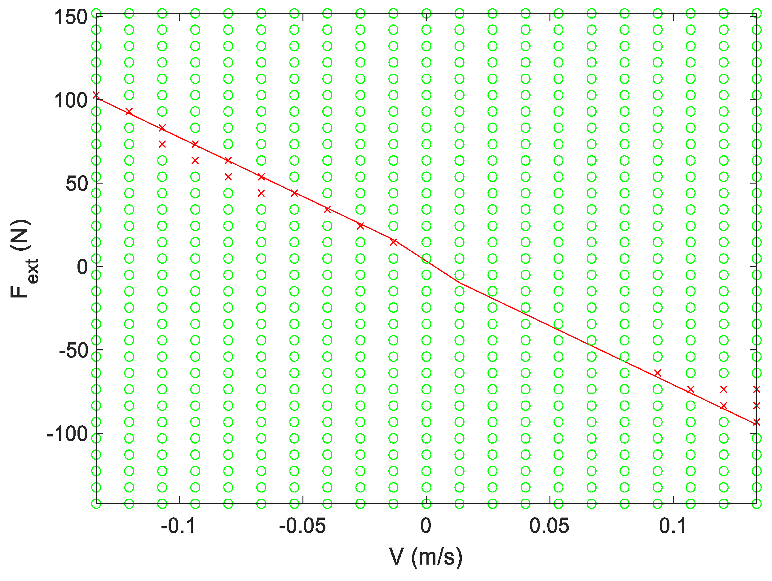
However, as shown in Figure 5, it is possible to excite a limit cycle, with the pressure continually oscillating. This instability has been identified in the literature [15,16,17] as being related to mode-switching of the shuttle valve spool around a critical external force when . In [15], it is stated that the size of the unstable region around the critical force is related to the shuttle spool centering spring and orifice geometry. Following this theory, eliminating the spring (as in this paper) would represent an infinitesimal unstable zone. However, we still observe a small unstable zone, as shown in Figure 6. Luckily, this zone is very small, and it may be possible to mitigate the effects by adding leakage or pressure feedback [17].
5. Conclusions
This paper presents a dynamic model of a single-rod electrohydrostatic actuator with a novel 3D-printed shuttle valve. These dynamic results indicate that a known issue with stability is small with this valve, but is not entirely eliminated. Future work will further develop our understanding of the causes of this limit cycle with the aim of eliminated it. The dynamic model will also be used to optimize system parameters.
Author Contributions
T.W. conceived and designed the experiments and model, and analysed the data; B.D. performed background research. Both contributed to writing the paper. All authors have read and agreed to the published version of the manuscript.
Acknowledgments
This research and APC were funded by Natural Sciences and Engineering Research Council of Canada, grant number 2017-05906. The authors wish to acknowledge Joe Murray of the Lil Giants Construction Co YouTube Channel for the donation of some preliminary equipment while international shipments were delayed during the COVID-19 pandemic.
Conflicts of Interest
The authors declare no conflict of interest.
Abbreviations
The following abbreviations are used in this manuscript:
| EHA | Electrohydrostatic Actuator |
References
- Ketelsen, S.; Padovani, D.; Andersen, T.O.; Ebbesen, M.K.; Schmidt, L. Classification and Review of Pump-Controlled Differential Cylinder Drives. Energies 2019, 12, 1293. [Google Scholar] [CrossRef]
- Merritt, H.E. Hydraulic control systems. J. Wiley 1967. [Google Scholar] [CrossRef]
- Ketelsen, S.; Kolks, G.; Andersen, T.O.; Schmidt, L.; Weber, J. Bootstrap Reservoir Concepts for Electro-Hydraulic Compact Cylinder Drives. 12th International Fluid Power Conference (12. IFK), Dresden, 12–14 October 2020. [Google Scholar]
- Zhang, S.; A Minav, T.; Pietola, M. Decentralized Hydraulics for Micro Excavator. In Proceedings of the 13th International Modelica Conference, Regensburg, Germany, 4–6 March 2019. [Google Scholar] [CrossRef]
- Wiens, T.; Bitner, D. An Efficient, High Performance and Low-Cost Energy Recovering Hydrostatic Linear Actuator Concept. In BATH/ASME 2016 Symposium on Fluid Power and Motion Control; Univeristy of Bath: Bath, UK, 2016. [Google Scholar]
- Wiens, T. An efficient, compact and low-cost Dual Cylinder Hydrostatic Actuator (DCHA). Int. J. Fluid Power 2018, 19, 80–90. [Google Scholar] [CrossRef]
- Achten, P.J.; Palmberg, J.O. What a difference a hole makes: The commercial value of the Innas hydraulic transformer. In The Sixth Scandinavian International Conference on Fluid Power (Tampere, May 26-28 1999, Proceedings); University of Tampere: Tampere, Finland, 1999; pp. 873–886. [Google Scholar]
- Costa, G.K.; Sepehri, N. Four-Quadrant Analysis and System Design for Single-Rod Hydrostatic Actuators. J. Dyn. Syst. Meas. Control. 2018, 141, 021011. [Google Scholar] [CrossRef]
- Adams, C. A380: ‘More Electric’ Aircraft. Aviation Today, October 2001. [Google Scholar]
- Parker. Compact Electro-Hydraulic Actuator (EHA). 2020. Available online: https://www.parker.com/Literature/Hydraulic%20Pump%20Division/Oildyne%20EHA/Compact-EHA-Catalog-HY22-3101E-7-13.pdf (accessed on 16 November 2020).
- Actuonix Motion Devices. Miniature Linear Motion Series-L16. 2019. Available online: https://s3.amazonaws.com/actuonix/Actuonix+L16+Datasheet.pdf (accessed on 27 October 2020).
- Odrive Robotics. Odrive High Performance Motor Control. Available online: https://odriverobotics.com/ (accessed on 27 October 2020).
- Wiens, T.; Deibert, B. A Low-cost Miniature Electrohydrostatic Actuator System. Actutors 2020, 9, 130. [Google Scholar] [CrossRef]
- Bonchis, A.; Corke, P.I.; Rye, D.C. A pressure-based, velocity independent, friction model for asymmetric hydraulic cylinders. In Proceedings of the 1999 IEEE International Conference on Robotics and Automation (Cat. No.99CH36288C), Detroit, Michigan, 10–15 May 1999. [Google Scholar] [CrossRef]
- Caliskan, H.; Balkan, T.; Platin, B.E. A Complete Analysis and a Novel Solution for Instability in Pump Controlled Asymmetric Actuators. J. Dyn. Syst. Meas. Control. 2015, 137, 091008. [Google Scholar] [CrossRef]
- Wang, L.; Book, W.J.; Huggins, J.D. A Hydraulic Circuit for Single Rod Cylinders. J. Dyn. Syst. Meas. Control. 2011, 134, 011019. [Google Scholar] [CrossRef]
- Wang, L.; Book, W.J. Using Leakage to Stabilize a Hydraulic Circuit for Pump Controlled Actuators. J. Dyn. Syst. Meas. Control. 2013, 135, 061007. [Google Scholar] [CrossRef]
Figure 1.
Photos of system, including (1) hydraulic cylinder, (2) pressure transducers, (3) 3D printed valve, (4) mounting plate, (5) pump, (6) charge pump line, and (7) motor. A cm ruler is included for scale. (Note that this photo was taken before bleeding air from the system.).
Figure 1.
Photos of system, including (1) hydraulic cylinder, (2) pressure transducers, (3) 3D printed valve, (4) mounting plate, (5) pump, (6) charge pump line, and (7) motor. A cm ruler is included for scale. (Note that this photo was taken before bleeding air from the system.).

Figure 2.
System schematic and nomenclature.

Figure 3.
Cutaway view of the 3D-printed PETG valve. The conical structure at the bottom is a support required during printing and is removed by gripping the hexagonal shape on the top of the spool and twisting. For both valves, pressures and are connected via passageways through the casing (not clearly visible here) to the top and bottom chambers, and the charge pressure is connected to the center of the casing between the two hemispherical sealing surfaces. 3D-printed threads at the top and bottom accommodate pressure transducers for the prototype valve, which may be eliminated if not required.

Figure 4.
Example step responses, for a range of external load forces (different rows) and commanded velocities (different colors). Colors represent the same command velocity in each plot. Velocities are shown in (a), (c), (e) and pressures in (b), (d), (f).
Figure 4.
Example step responses, for a range of external load forces (different rows) and commanded velocities (different colors). Colors represent the same command velocity in each plot. Velocities are shown in (a), (c), (e) and pressures in (b), (d), (f).


Figure 5.
An example of a pressure limit cycle for = −148.5 mm/s and (a), enlarged in Frame (b).
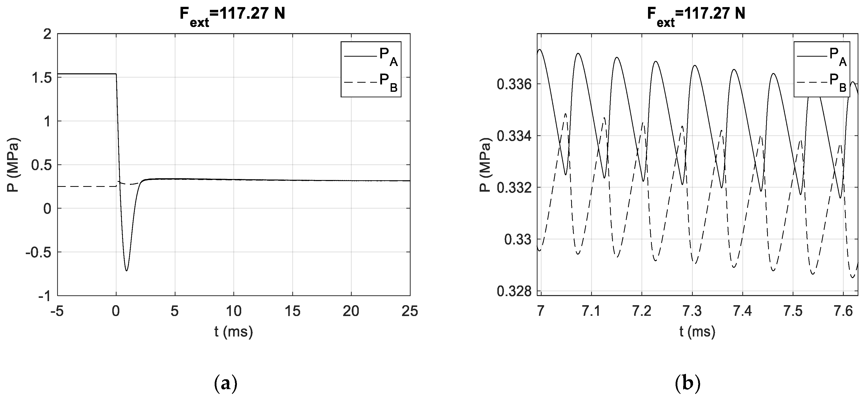
Figure 6.
An oscillating pressure-limit cycle exists for the points denoted by a red x, while no oscillations exist for green circles. The red line denotes the critical load force where at equilibrium.
Figure 6.
An oscillating pressure-limit cycle exists for the points denoted by a red x, while no oscillations exist for green circles. The red line denotes the critical load force where at equilibrium.

Table 1.
Model Parameters.
| Parameter | Value |
|---|---|
| 78.5 mm2 | |
| 66.0 mm2 | |
| 28.3 cP | |
| 1.0 GPa | |
| 2.50 × 10⁴ N/(m/s)/(Pa s) | |
| 3.41 N | |
| 5.27 × 10⁻⁶ N/(m/s)/Pa | |
| 0.01 mm/s | |
| 1.25 kg | |
| 1.23 × 10¹² Pa/(m3/s) | |
| 6.83 × 10¹⁴ Pa/(m3/s) | |
| 2.41 × 10¹² Pa/(m3/s) | |
| 1.11 × 10¹¹ Pa/(m3/s) | |
| 5.29 × 10⁹ Pa/(m3/s) | |
| 50.3 mm2 | |
| 12.2 N/(m/s) | |
| 1.2 g | |
| 2 mm | |
| −2 mm | |
| 2.55 mL | |
| 2.24 mL | |
| 250 kPa | |
| 0.7 L/min |
Publisher’s Note: MDPI stays neutral with regard to jurisdictional claims in published maps and institutional affiliations. |
© 2021 by the authors. Licensee MDPI, Basel, Switzerland. This article is an open access article distributed under the terms and conditions of the Creative Commons Attribution (CC BY) license (https://creativecommons.org/licenses/by/4.0/).
Share and Cite
MDPI and ACS Style
Wiens, T.; Deibert, B. A Low-Cost Miniature Electrohydrostatic Actuator. Proceedings 2020, 64, 35. https://doi.org/10.3390/IeCAT2020-08488
AMA Style
Wiens T, Deibert B. A Low-Cost Miniature Electrohydrostatic Actuator. Proceedings. 2020; 64(1):35. https://doi.org/10.3390/IeCAT2020-08488
Chicago/Turabian StyleWiens, Travis, and Brendan Deibert. 2020. "A Low-Cost Miniature Electrohydrostatic Actuator" Proceedings 64, no. 1: 35. https://doi.org/10.3390/IeCAT2020-08488