
Development of Triboelectric Devices for Human–Machine Interface Applications †


Institute of Nanoscience and Nanotechnology (INN), NCSR ‘Demokritos’, 15310 Athens, Greece
*
Author to whom correspondence should be addressed.
†
Presented at the XXXV EUROSENSORS Conference, Lecce, Italy, 10–13 September 2023.
Proceedings 2024, 97(1), 7; https://doi.org/10.3390/proceedings2024097007
Published: 13 March 2024
Abstract
:Haptic feedback, also known as tactile sensing, plays a vital role in human interactions with the external environment. The artificial replication of tactile sensations using triboelectric sensors has sparked the attention of the scientific community by developing advanced electronic skins with haptic perception. In this work, we design and fabricate different flexible tactile sensors based on the triboelectric effect. The triboelectric sensors were evaluated in respect of their ability to identify different materials that were in contact with the sensor. Our results show that the triboelectric signal depends on the nature of the substrate, and a clear distinction among different substrates could be obtained.
1. Introduction
The sense of touch allows individuals to gather information about objects in their surroundings and perceive their textures, playing a pivotal role in emotional and social interactions as well as in everyday tasks. The artificial replication of tactile sensation using triboelectric sensors has sparked the attention of the scientific community by developing advanced electronic skins with haptic perception [1,2,3]. In this work, we present the design, fabrication and characterization of a flexible and wearable tactile sensor, based on the triboelectric effect, in the form of electronic skin.
2. Materials and Methods
The sensor is designed to follow the contour of the fingertip, enabling the detection of the material and texture of an object through contact triboelectrification. The fabrication of the sensor was facilitated by the deposition of metal thin-films on flexible substrates using standard thin-film deposition methods. For the fabrication of the tactile sensor, two electrodes were used in a braided form (parallel metal conductors with an alternating pattern). Various geometries were evaluated. The dimensions of the electrodes were chosen based on the surface of the finger where the sensor is placed (Figure 1a). The sensors were fabricated (Figure 1a,b) by metal deposition (Al and Cu) on Kapton® (75 μm) and on a flexible printed circuit board (FPCB) (100 μm).
Electrical characterization was performed using an oscilloscope (Figure 2a). To limit the effects of charging and the exchange of the electrical charges of human skin with the sensor, the finger was covered with a nitrile glove and the substrates were adhered to it with biocompatible double-sided tape. The contact material of the sensor with the different surfaces of materials studied in the experimental procedures was placed on top of the electrodes, covering them, and adhered to the substrate with non-conductive Kapton tape (Figure 1c).
3. Discussion
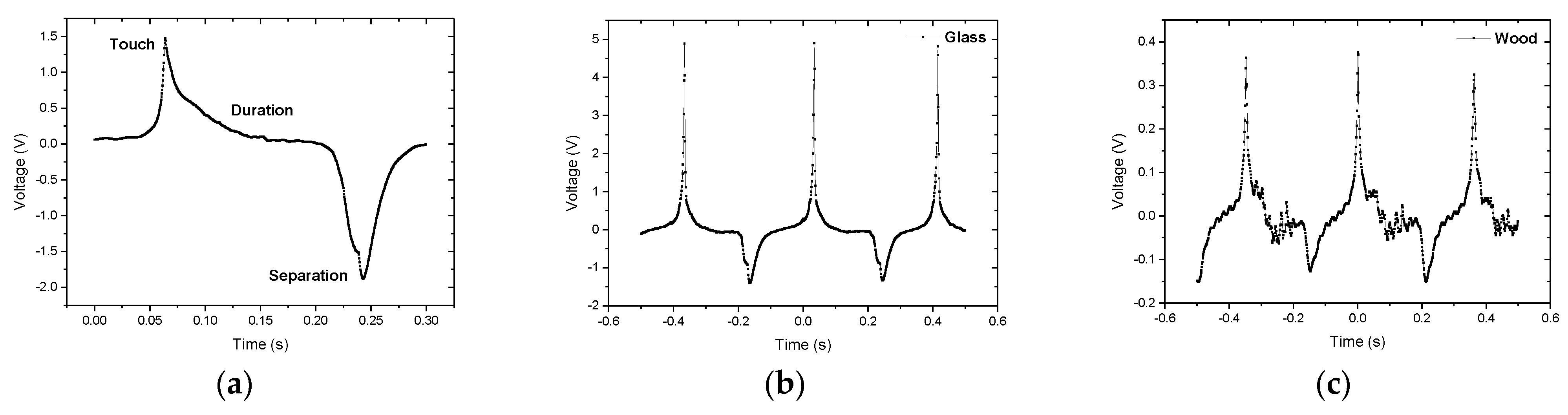
To assess the sensor’s ability to recognize different materials, experiments were conducted on surfaces such as wood, glass and human skin. The triboelectric tactile sensor detects changes in the electrical charge of its surface due to a mechanical movement that causes two materials to come into contact. The electrical output signal (Figure 2a) contains information about the type of material, its roughness and the pressure exerted on it and works without the need for an external power source. Ιn the electrical signal, there is a unique surface depiction of unevenness for each material (Figure 2b,c).
Author Contributions
Conceptualization, A.A., V.Z. and C.T.; methodology, A.A., V.Z. and A.B.; writing—original draft preparation, A.A. and V.Z.; writing—review and editing, all authors; supervision, C.T. All authors have read and agreed to the published version of the manuscript.
Funding
This research received no external funding.
Institutional Review Board Statement
Not applicable.
Informed Consent Statement
Not applicable.
Data Availability Statement
Data are contained within the article.
Acknowledgments
The authors acknowledge the technical support from the Nanotechnology and Microsystems Laboratory at the Institute of Nanoscience and Nanotechnology, NCSR “Demokritos”.
Conflicts of Interest
The authors declare no conflict of interest.
References
- Zhu, P.; Peng, H.; Rwei, A.Y. Flexible, wearable biosensors for digital health. Med. Nov. Technol. Devices 2022, 14, 100118. [Google Scholar] [CrossRef]
- Nan, X.; Wang, X.; Kang, T.; Zhang, J.; Dong, L.; Dong, J.; Xia, P.; Wei, D. Review of Flexible Wearable Sensor Devices for Biomedical Application. Micromachines 2022, 13, 1395. [Google Scholar] [CrossRef] [PubMed]
- Prajapati, S.; Padhan, B.; Amulyasai, B.; Sarkar, A. Nanotechnology-based sensors. In Biopolymer-Based Formulations: Biomedical and Food Applications; Elsevier: Amsterdam, The Netherlands, 2020; pp. 237–262. [Google Scholar] [CrossRef]
Figure 1.
(a) Sensor fabricated by aluminum deposition on Kapton® substrate. (b) Sensors on printed circuit board. (c) Sensor stuck with biocompatible double-sided tape on a human finger covered with a nitrile glove.
Figure 1.
(a) Sensor fabricated by aluminum deposition on Kapton® substrate. (b) Sensors on printed circuit board. (c) Sensor stuck with biocompatible double-sided tape on a human finger covered with a nitrile glove.
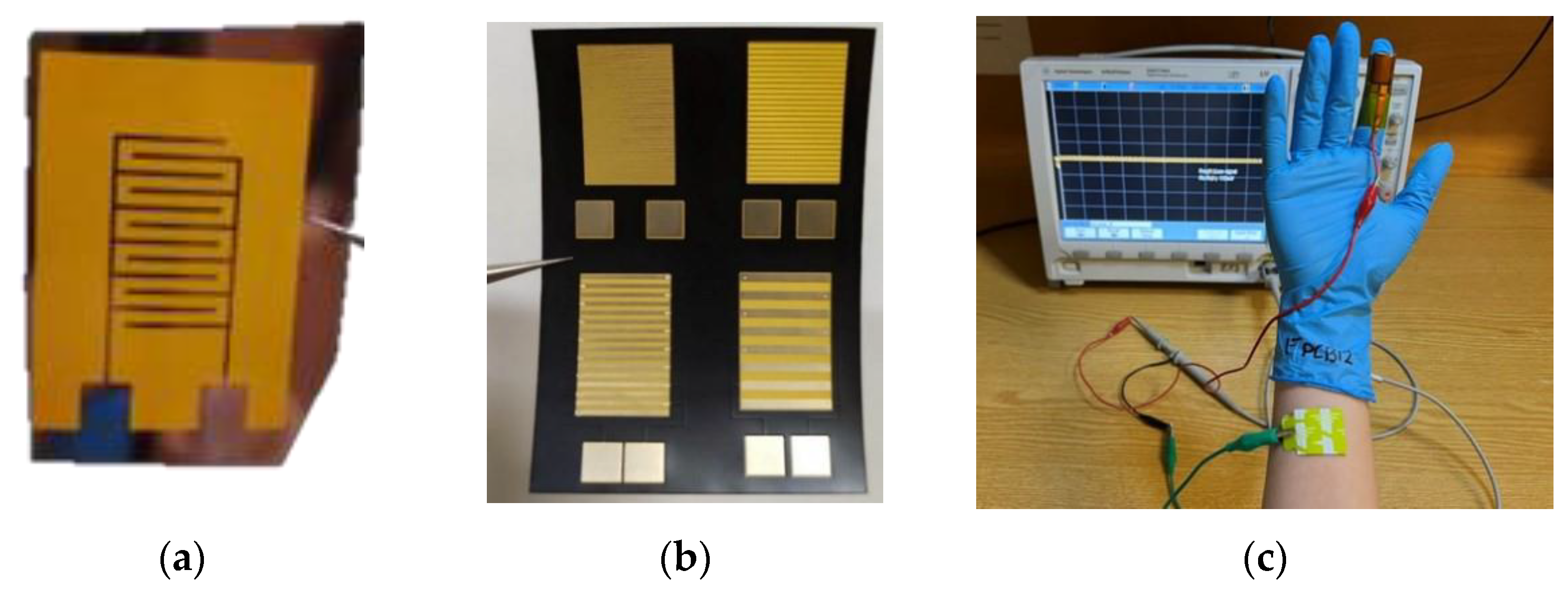
Figure 2.
(a) Connecting the sensor to the oscilloscope; (b) output electric signal. (c) Representative signals for each material in contact with a sensor (glass).
Figure 2.
(a) Connecting the sensor to the oscilloscope; (b) output electric signal. (c) Representative signals for each material in contact with a sensor (glass).
Disclaimer/Publisher’s Note: The statements, opinions and data contained in all publications are solely those of the individual author(s) and contributor(s) and not of MDPI and/or the editor(s). MDPI and/or the editor(s) disclaim responsibility for any injury to people or property resulting from any ideas, methods, instructions or products referred to in the content. |
© 2024 by the authors. Licensee MDPI, Basel, Switzerland. This article is an open access article distributed under the terms and conditions of the Creative Commons Attribution (CC BY) license (https://creativecommons.org/licenses/by/4.0/).
Share and Cite
MDPI and ACS Style
Anastasopoulos, A.; Zacharia, V.; Bardakas, A.; Tsamis, C. Development of Triboelectric Devices for Human–Machine Interface Applications. Proceedings 2024, 97, 7. https://doi.org/10.3390/proceedings2024097007
AMA Style
Anastasopoulos A, Zacharia V, Bardakas A, Tsamis C. Development of Triboelectric Devices for Human–Machine Interface Applications. Proceedings. 2024; 97(1):7. https://doi.org/10.3390/proceedings2024097007
Chicago/Turabian StyleAnastasopoulos, Andreas, Vasiliki Zacharia, Achilleas Bardakas, and Christos Tsamis. 2024. "Development of Triboelectric Devices for Human–Machine Interface Applications" Proceedings 97, no. 1: 7. https://doi.org/10.3390/proceedings2024097007