Numerical Study of a Direct Injection Internal Combustion Engine Burning a Blend of Hydrogen and Dimethyl Ether


1
CFDLAB, Technion—Israel Institute of Technology, Faculty of Mechanical Engineering, Haifa 3200002, Israel
2
TICEL, Technion—Israel Institute of Technology, Faculty of Mechanical Engineering, Haifa 3200002, Israel
*
Author to whom correspondence should be addressed.
Drones 2018, 2(3), 23; https://doi.org/10.3390/drones2030023
Submission received: 24 June 2018
/
Revised: 17 July 2018
/
Accepted: 19 July 2018
/
Published: 24 July 2018
(This article belongs to the Special Issue UAV Propulsion)
Abstract
:In the reported study, various aspects of dimethyl ether/hydrogen combustion in a Reactivity Controlled Compression Ignition (RCCI) engine are numerically evaluated using Reynolds Averaged Navier-Stokes (RANS) and Large Eddy Simulation (LES). Early direct injection and mixture propagation were also explored, along with peculiaritis of dimethyl ether combustion modeling. The numerical models are validated using available experimental results of a partially premixed dimethyl ether jet flames and an optically accessible internal combustion engine with direct hydrogen injection. LES showed more predictive results in modeling both combustion and mixture propagation. The same models were applied to a full engine cycle of an RCCI engine with stratified reactivity, to gain phenomenological insight into the physical processes involved in stratified reactivity combustion. We showed that 3D and turbulence considerations had a great impact on simulation results, and the LES was able to capture the pressure oscillations typical for this type of combustion.
1. Introduction
While powertrain technologies are becoming increasingly hybridized and electrified, internal combustion engine (ICEs) are expected to keep playing a dominant role in heavy-duty road transport, maritime propulsion and other applications [1]. In order to meet the increasingly stringent emission standards, both for pollutants and greenhouse emissions, new combustion concepts are being developed [2].
These combustion concepts could also lend themselves to drone propulsion, as they are able to extend the operating conditions for drones, especially for drones classified as HALE (high altitude, long endurance). Hydrogen can be used as an alternative fuel in order to increase flight altitude, as its stoichiometric combustion requires smaller amounts of air when compared to iso-octane [3]. This improvement is achievable without the added weight of a turbocharger, thus enabling the drone to remain airborne for longer periods of time, at high altitudes. This work establishes the first steps in developing a reforming controlled compression ignition (RefCCI) engine which could burn hydrogen rich reforming products, paving the way to improve HALE drones capabilities.
Low temperature combustion (LTC) aims to combine the high operating efficiency which allows ICEs to minimize CO emissions, and the low NO and particulate matter (PM) formation. The homogeneous charge compression ignition (HCCI) engine is an implementation of LTC, operating with a homogeneous fuel-air mixture, typically prepared by port fuel injection (PFI) or early direct injection (DI). The mixture is ignited by compression, so high compression ratios are preferable, and, in some cases, highly reactive fuels. HCCI is a kinetically-controlled combustion process, thus presenting a great challenge for engineering applications. The power output in HCCI is controlled by the fuel input, while maintaining an air-to-fuel equivalence ratio of .
Inagaki et al. [4] investigated dual-fuel premixed compression ignition, and Kokjohn et al. [5] named this type of combustion RCCI and further developed the method. The RCCI concept uses two or more fuels, each with a different reactivity, blended to adjust the overall reactivity for each operating range. This allows for combustion to take place in stages, combining direct injection strategies to create stratified fuel mixtures, for example, by using an early DI of the lower reactivity fuel to create a homogeneous mixture. The RCCI concept had shown better control capabilities than other HCCI implementations together with thermal efficiencies reaching [6].
RCCI was extensively researched in recent years, with most of the efforts focusing either on Reynolds-Averaged Navier Stoked (RANS) CFD simulations, or in single-cylinder research engine experiments [1]. In a review by Reitz and Duraisamy [6], experimental and modeling work focusing on RCCI was summarized. The effects of fuel, injection pressure and timing, piston geometry and other engine parameters were discussed in detail. Simulations and modeling studies (3D RANS simulations and 1D modeling studies) were very effective in guiding experimental studies, achieving high efficiency and high load operation. Main findings showed RCCI to be a promising strategy for HCCI combustion: demonstrating an ability to meet emission regulations of NO and PM without aftertreatment; high thermal efficiency over a variety of operating conditions, with a peak of 56%; exhaust gas recirculation (EGR) effectively lowered NO emissions by two orders of magnitude and soot by a factor of ten; low reactivity fuels and mass split injection strategies were effective in extending load limits, decreasing PRR and ringing intensity. The scope for future work was also outlined, emphasizing the role of optimization and improving performance. This will be achieved by researching fuel injection strategies, different fuel blends and further studies at higher speeds and loads.
A review on the subject by Li et al. [7] showed recent progress in management of RCCI combustion. The effects of fuel ratios, injection strategies, EGR rates and piston bowl shapes were studied, in addition to different fuel combinations. The use of two injectors, one for each fuel, was found to be able to extend the engine’s load limits. The important role renewable and oxygenated fuels have in improving combustion processes has been pointed out, with further research required. The control and timing of HRR remains one of the biggest challenges to RCCI combustion, especially at high loads. Simulation studies mentioned in the review used a sector mesh, assuming homogeneously distributed low reactivity fuel and not including intake and exhaust valves in the simulation. Further efforts should include a fuller geometry, and no assumptions of homogeneity. Other simulations studies from recent years used RANS turbulence modeling (such as Nazemi and Shahbakhti [8] or Rahnama et al. [9]).
While RANS models can reproduce some of the associated phenomena in ICEs, LES offers significant advantages when studying phenomena that lead to cycle-to-cycle variability (CCV), such as combustion instabilities, ringing, misfires or flame quenching. In [10,11], LES was applied and shown to capture fine flow structures, and thus describe unsteady, spatially anisotropic phenomena such as temperature and fuel mixture stratification, autoignition and flame propagation in IC engines. RANS simulations are limited in their abilities to capture the intrinsically time-dependent phenomena of flame propagation and flame-turbulence interaction, unlike LES simulations which resolve local and transient features [12].
A novel waste heat recovery and onboard hydrogen production technology called High-Pressure Thermochemical Recuperation (HP-TCR) is developed at the Technion [13,14,15]. It can be combined with RCCI combustion, thus multiplying great benefits of both technologies and providing an excellent method of HCCI control. The Reforming-Controlled Compression Ignition based on the onboard production of hydrogen and controlled combustion of H2 and DME is being studied at the Technion using HP-TCR [16,17]. A primary fuel DME is reformed onboard to hydrogen-rich reformate using waste heat of exhaust gases. Varying ratios of DME and H are used to control ignition timing and combustion phasing at different loads and speeds, improving energy efficiency and reducing pollutants over a wide range of operating regimes. This study is focused on recognizing and analyzing the modeling challenges specific to an RCCI engine and H and DME combustion. By comparing 1D and 3D modeling approaches, the effects of reactivity variability and stratification in the RCCI engine, such as turbulence, temperature stratification and mixing in the engine cylinder are evaluated.
2. Numerical Models and Validation
2.1. Computational Model
Numerical simulations were performed using the commercial software CONVERGE [18]. CONVERGE uses a modified cut-cell Cartesian grid generation method which is generated during runtime, along with adaptive mesh refinement (AMR) which refines the grid based on fluctuating and moving scalars or velocities. The governing equations are discretized using a finite-volume approach and are solved with a second-order accurate spatial scheme. Time integration is solved implicitly with first order accuracy, and the time step is calculated at each cycle based on a maximum CFL number for velocity and Mach number.
Two different turbulent modeling approaches were applied. The first was Reynolds Averaged Navier-Stokes (RANS) with the re-normalization group (RNG) model. The second was Large eddy simulation (LES) with the zero-equation dynamic Smagorinsky model. Chemistry modeling is done using a detailed chemistry model, SAGE [19], with the Fischer/Kaiser [20] reaction mechanism, composed of 78 species and 351 reactions.
2.2. Validation of Model
Two test cases were studied in order to estimate solver accuracy. The first, gauging the chemistry model and reaction mechanism, was of a partially premixed DME/air jet flame. Pilot stabilized turbulent DME/air jet flames were investigated in the Sydney/Sandia burner configuration [21,22]. The main DME/air jet flame series has a volumetric air-to-fuel ratio of 4:1, so that the stoichiometric mixture fraction is 0.35, same as for the 3:1 ratio in the methane/air Sandia flame series.
Two combustion modeling approaches were applied to the jet flame case. In addition to the RANS and LES simulations using the SAGE combustion model, a flamelet generated manifold (FGM) model was also used. The FGM model is not practical for modeling the dual fuel combustion of the RCCI engine, as it required a pre-definition of the mixture’s composition. However, the FGM model includes turbulence-chemistry interaction (TCI) modeling that does not exist in the SAGE model, which is important for an anchored flame with mixing-controlled combustion. The jet flame provides information about the intermediate species that are created in each stage of DME combustion, reflecting the two-stage ignition behavior that creates temperature stratification in the RCCI engine.
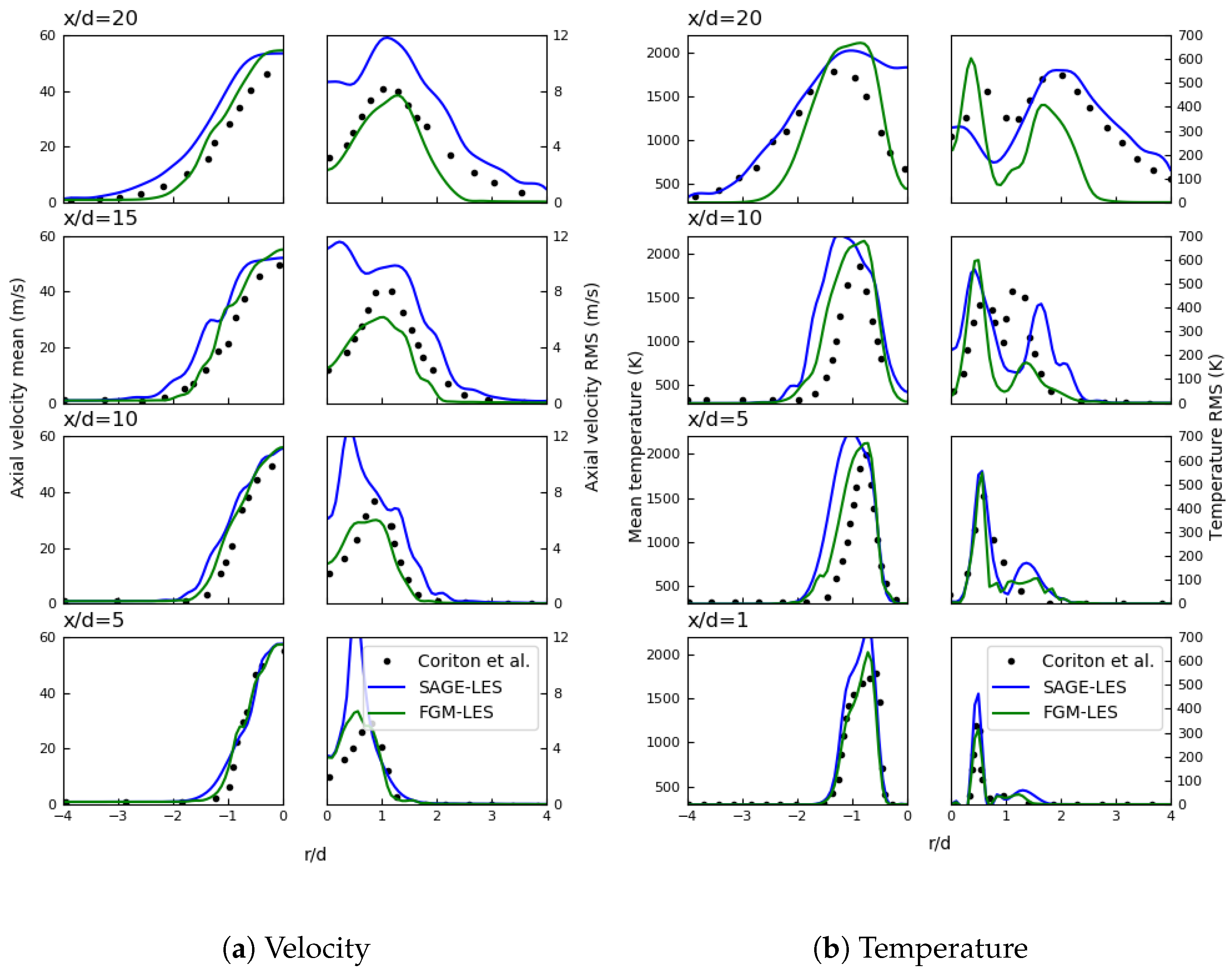
Figure 1 shows a comparison of computed LES and experimental radial profiles of the mean and RMS of axial velocity and temperature. The FGM simulations showed an overall good agreement with measured data, replicating the velocity field while slightly over predicting the flame temperature. The SAGE combustion model was able to capture trends and major species in DME combustion, however the lack of a TCI model led to large errors in the overall results. In combustion applications which exhibit more homogeneous conditions, the error stemming from the lack of TCI modeling has a smaller effect on both flow and combustion.
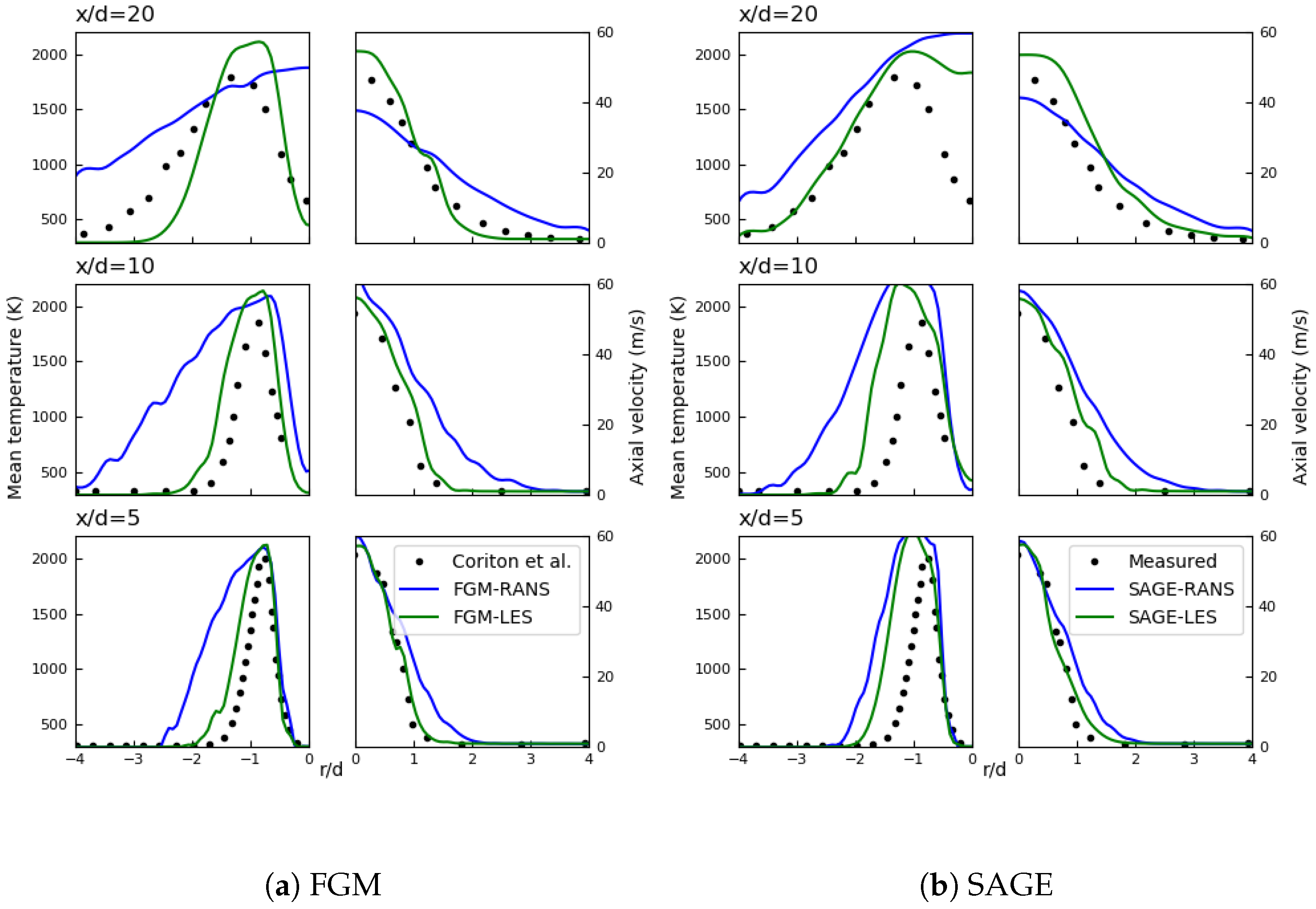
When comparing RANS simulations to LES (Figure 2), it is apparent that temperatures are higher than LES and experimental data. Because RANS simulations do not capture transient phenomena such as local extinction, the fuel consumption near the inlet is over predicted and so are the temperatures. This leads to an overall shorter flame.
The second case used for validation was of a hydrogen fueled IC engine with direct injection of hydrogen (DI-H2ICE) at motoring conditions. This engine was chosen due to its similarity in size and injection strategy to the RCCI engine, and the availability of velocity and scalar measurements done using PIV and PLIF [23,24]. Table 1 summarizes the engine specifications.
A base grid of mm was generated, with additional refinements of the grid in the cylinder region, where the grid before AMR is of mm. Embedded refinement around the injector nozzle and in the injected jet is used to capture the high velocity jet accurately, along with AMR based on velocity and temperature.
A comparison of LES and RANS simulation results to the experimental data from [25] (Figure 3) shows that near the end of the injection and the compression stroke the mixture vary between the simulations. At CA, maximum fuel concentrations in the cylinder can be considered to be an indication of fuel mixing. While the LES showed a maximum value of , similar to experimental results, the RANS simulation showed a maximum concentrations reaching . The RANS results shows more regions of higher concentration alongside areas to which the fuel has not reached. In contrast, the mixture that forms in the LES is more well-spread and similar to that observed in experiments. When considering combustion modeling the distribution of fuel is essential, and RANS will yield significantly different results, so that correct prediction of the fuel mixture propagation is essential for reacting flow simulations.
3. Reforming Controlled Compression Ignition (RefCCI) Engine Simulations
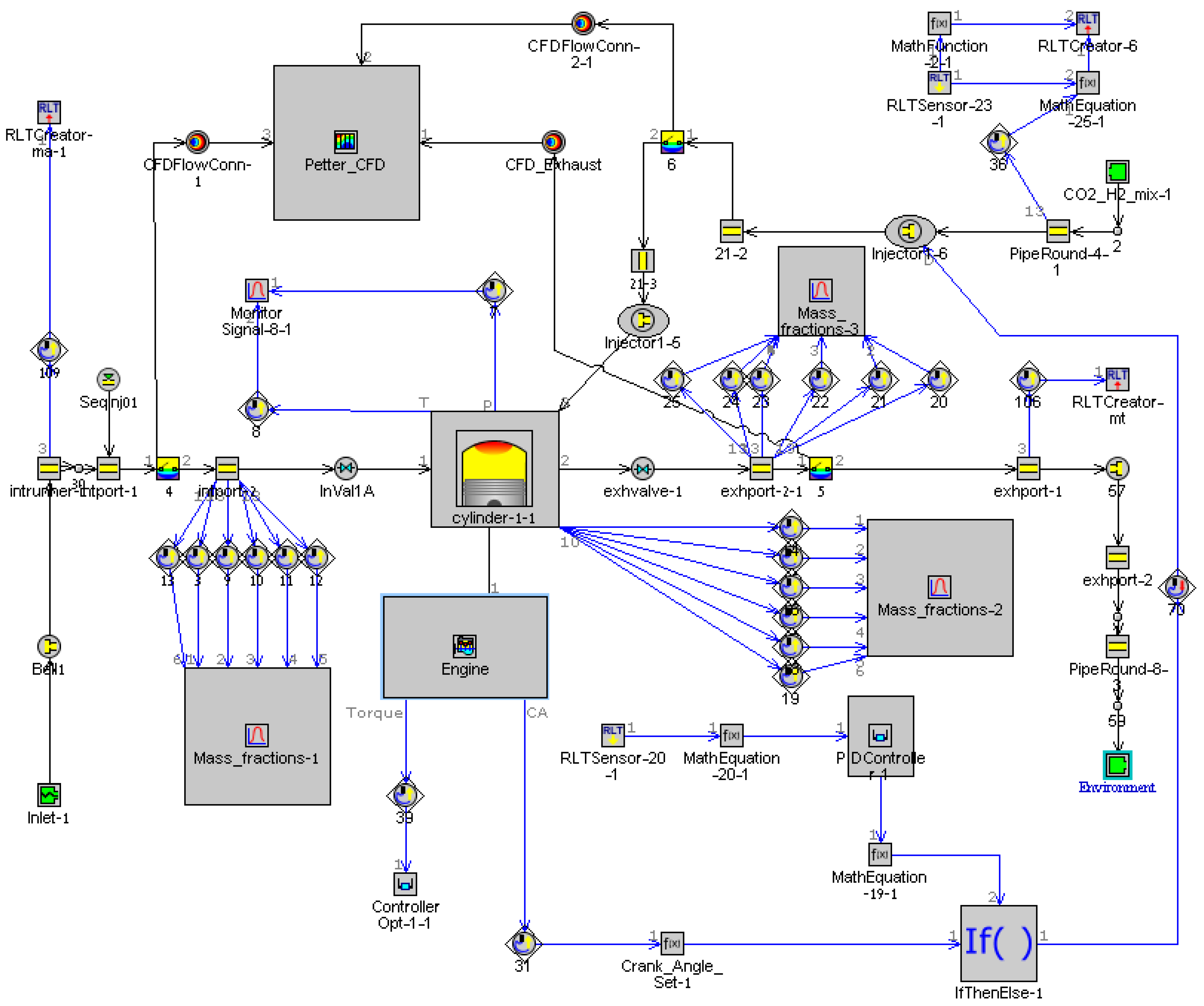
The RefCCI engine is based on a two-valve Lister-Petter AD1 diesel engine, converted to directly inject reformate—H and CO—with a port injection of DME. 1D simulations using GT-Power were used to calculate boundary and initial conditions for 3D RANS and LES computations. The CFD model was developed based on a 1D model of the engine built by Eyal and Tartakovsky [16] using the commercial software GT-Power, and engine specifications are given in Table 2. A PID controller is used to maintain a constant throughout the simulation. Combustion rates are predicted using the Fischer/Kaiser [20] kinetic reaction mechanism in a single-zone combustion model. The Woschni correlation for in-cylinder heat transfer modeling [26] is applied, and injected reformate composition is set to contain molar concentrations of H and CO. Engine load is set by choosing , and different ratios of DME to reformate are investigated. The complete GT-Power model of the engine, including the CFD coupling, is given in Figure 4.
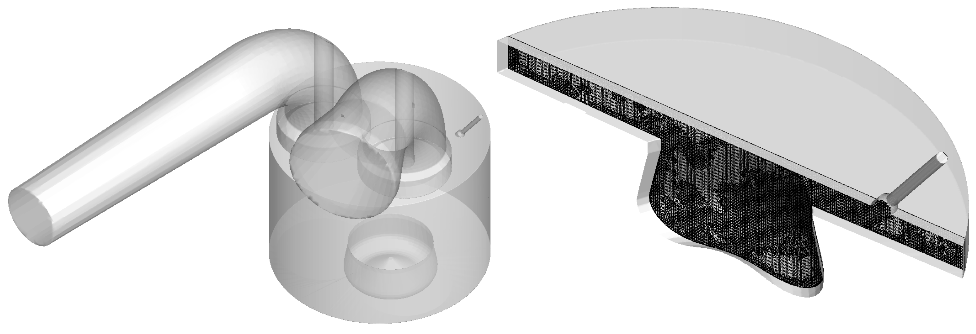
A CFD simulation was coupled with the 1D model and ran for one additional cycle after the GT-Power simulation has converged. Figure 5 shows the geometry and a slice of the mesh during injection. Turbulence was modeled using zero-equation dynamic Smagorinsky LES and RANS with the RNG model. Combustion was modeled using the detailed chemistry SAGE model. A mesh with a base grid size of 2.25 mm was generated for the LES and 4mm for RANS, with AMR based on temperature and velocity and limited to 10 M cells. Additional embedding is added in the cylinder, around intake and exhaust valves, as well as the injector nozzle.
The boundary conditions of the intake and exhaust ports are calculated in GT-Power to determine temperature and pressure, as well as the injection duration and composition of DME and reformate. The O’Rourke and Amsden heat transfer sub-model [27] is used to model heat loss through the cylinder wall. Initial conditions at the cylinder at BDC were also taken from the 1D simulation.
4. Results and Discussion
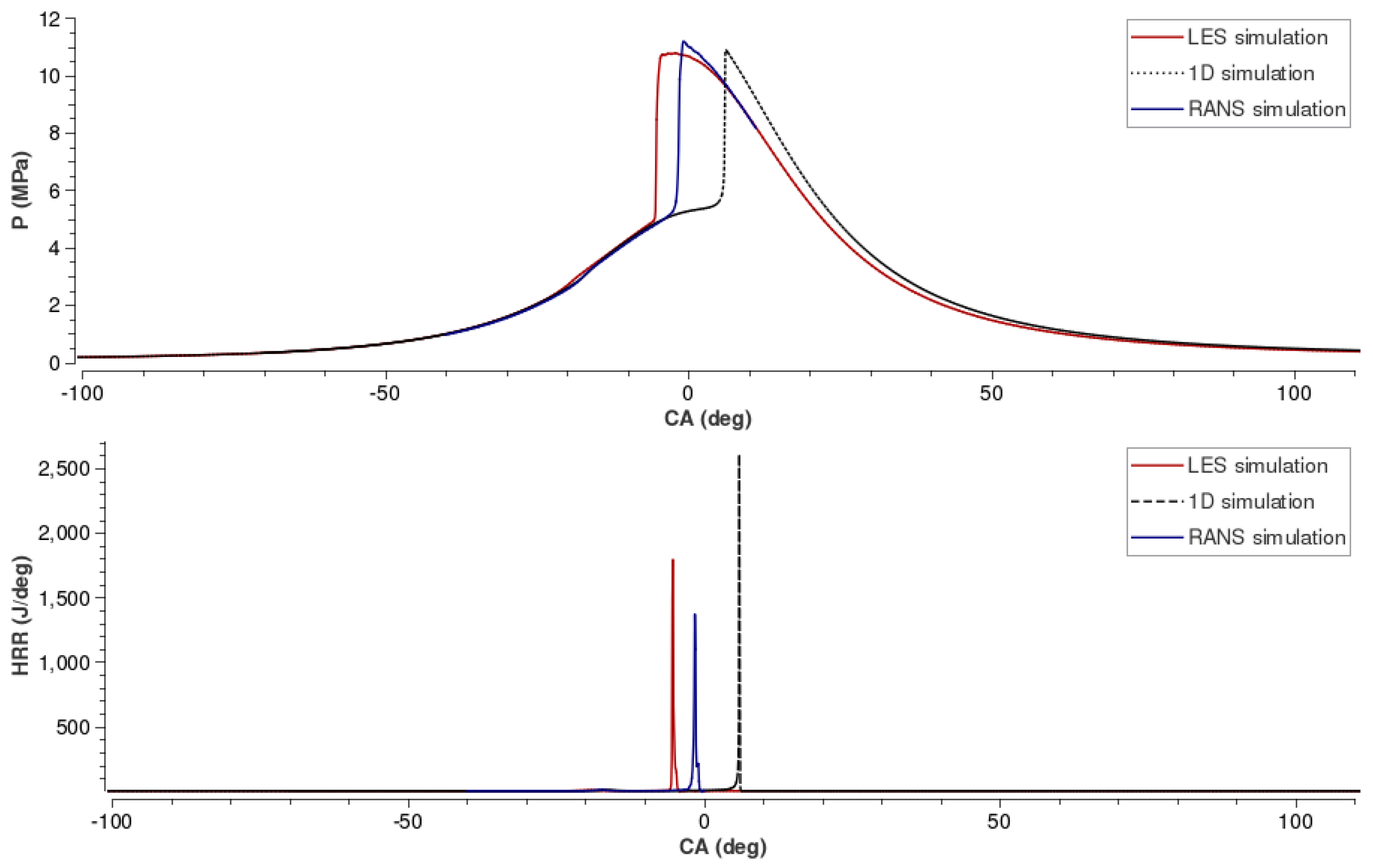
The case we examine is one with a H to DME molar ratio of 4.2. Figure 6 is a comparison of the pressure traces and heat release rates obtained with a 1D simulation in GT-Power and 3D-CFD simulations. The effects of flow modeling shift the ignition timing forward by 5CA in the case of the RANS simulation, and an additional 5 in the LES. The pressure trace of the LES simulation has a more rounded peak, and shows some weak oscillations after the initial pressure rise. When compared to the 1D, single zone simulations, the peak of HRR is significantly higher than the peak in the LES and RANS simulations. Heat release occurs more gradually with the addition of volumetric considerations—temperature and reactivity stratification—and turbulence modeling. Correct estimation of HRR is important for predicting ringing phenomena, which causes engine noise and, in some cases, mechanical damage [1].
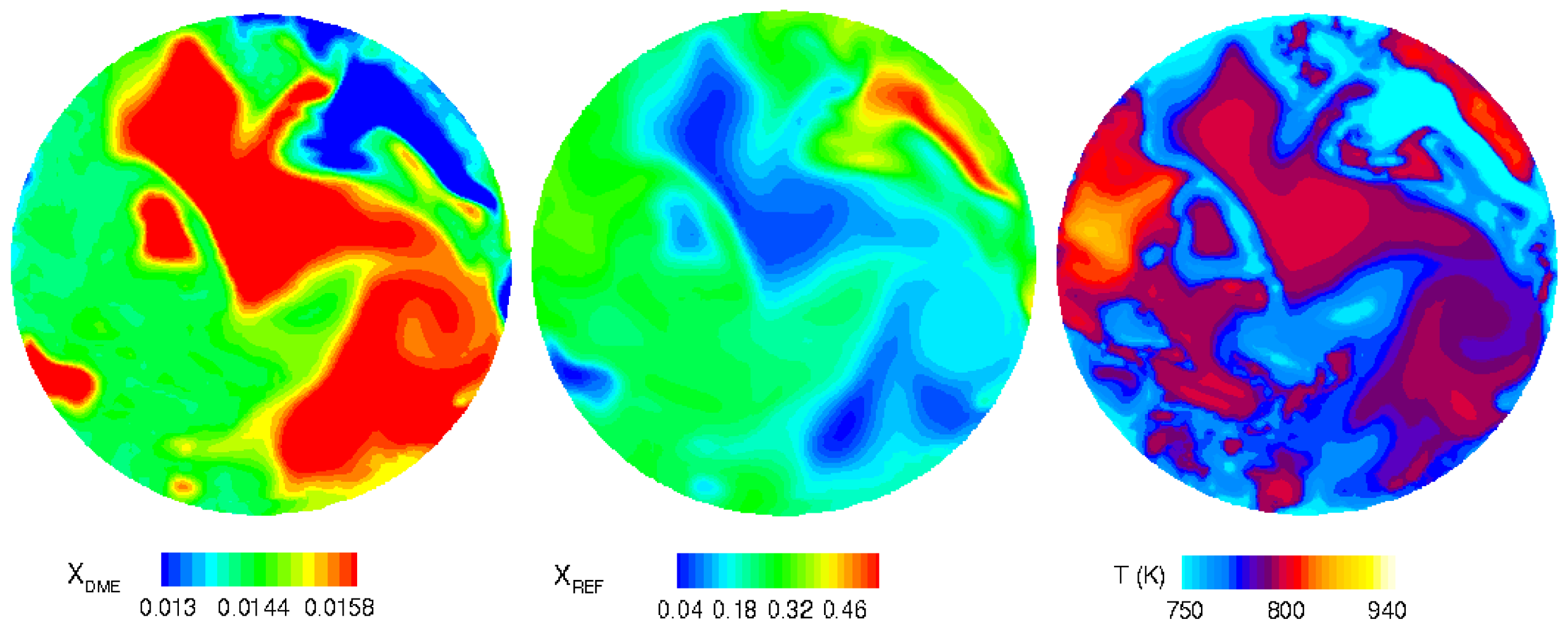
Figure 7 shows the temperature conditions and different fuel compositions right before the early heat release stage at t = −24CA. At this stage, temperatures in the cylinder vary by about 100 K, from 750 to 850 K. The DME-rich regions are warmer, where pre-combustion reactions are beginning to take place. The regions which are rich in reformate have a lower temperature, due to the high levels of CO and lower reactivity. These regions are not yet reacting, with the CO in the reformate further delaying ignition by lowering the peak temperature of the first stage of ignition (the CHO rich stage) [28].
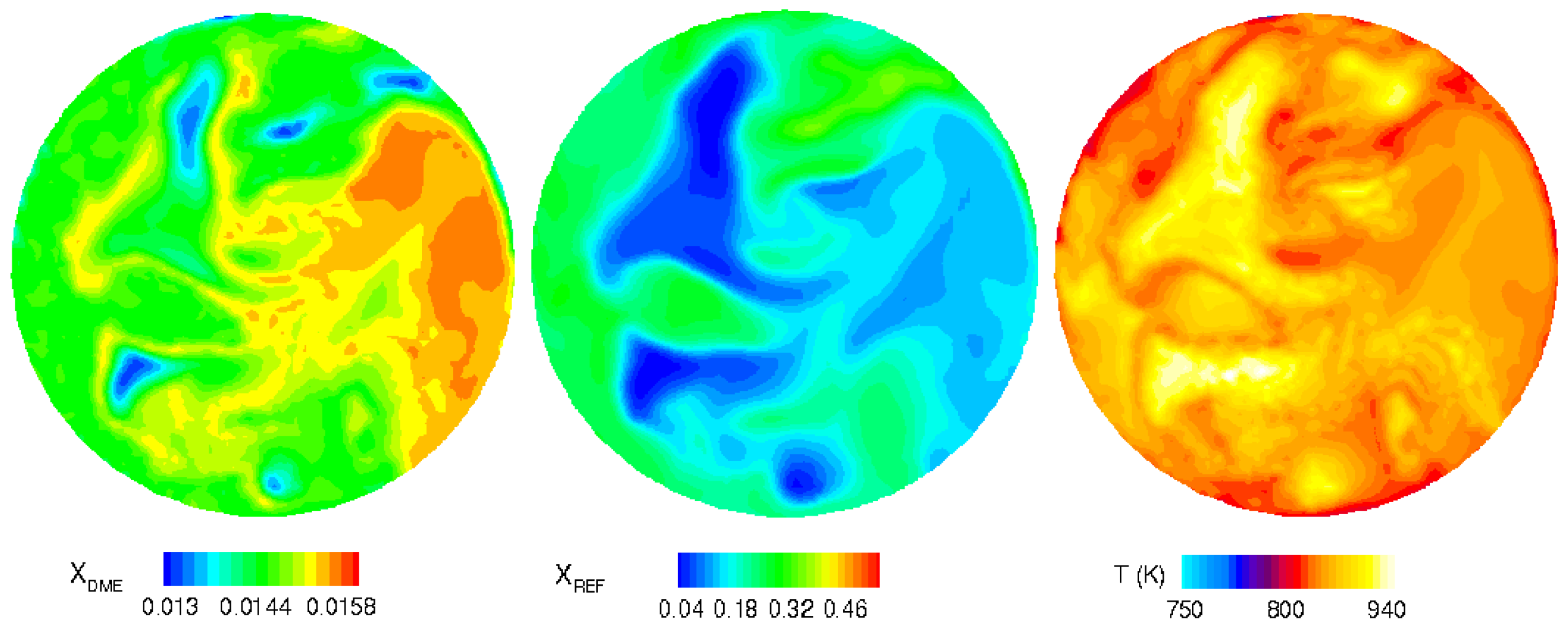
In Figure 8, the pre-ignition stage in the cylinder is shown. The regions that were rich in DME in Figure 7 are now the warmest, as the lower energy C-O bonds are broken before C-H bonds, releasing some energy at this stage and creating the intermediate species [29]. Peak temperatures in the cylinder are reach 1000 K, and vary in range of 200 K which creates temperature stratification in addition to the reactivity stratification of the different fuels.
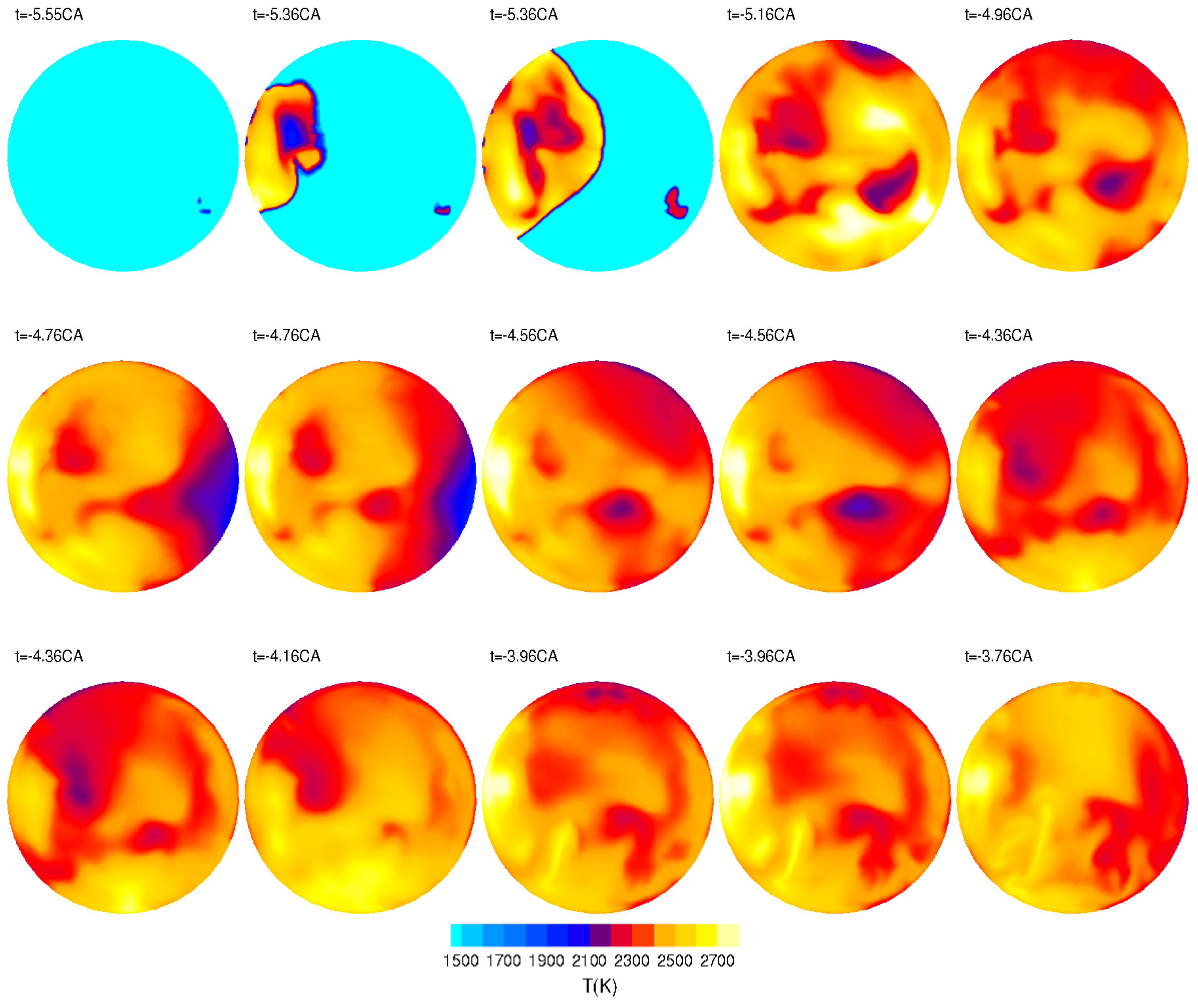
Figure 9 shows the flame propagation during ignition stage. Initially, there are two flame fronts which develop simultaneously (it should be noted that the temperature scale is different to the one in Figure 8). Within less than 0.5CA the flame fronts are joined and temperatures rise above 2200 K everywhere in the piston bowl as reactions take place.
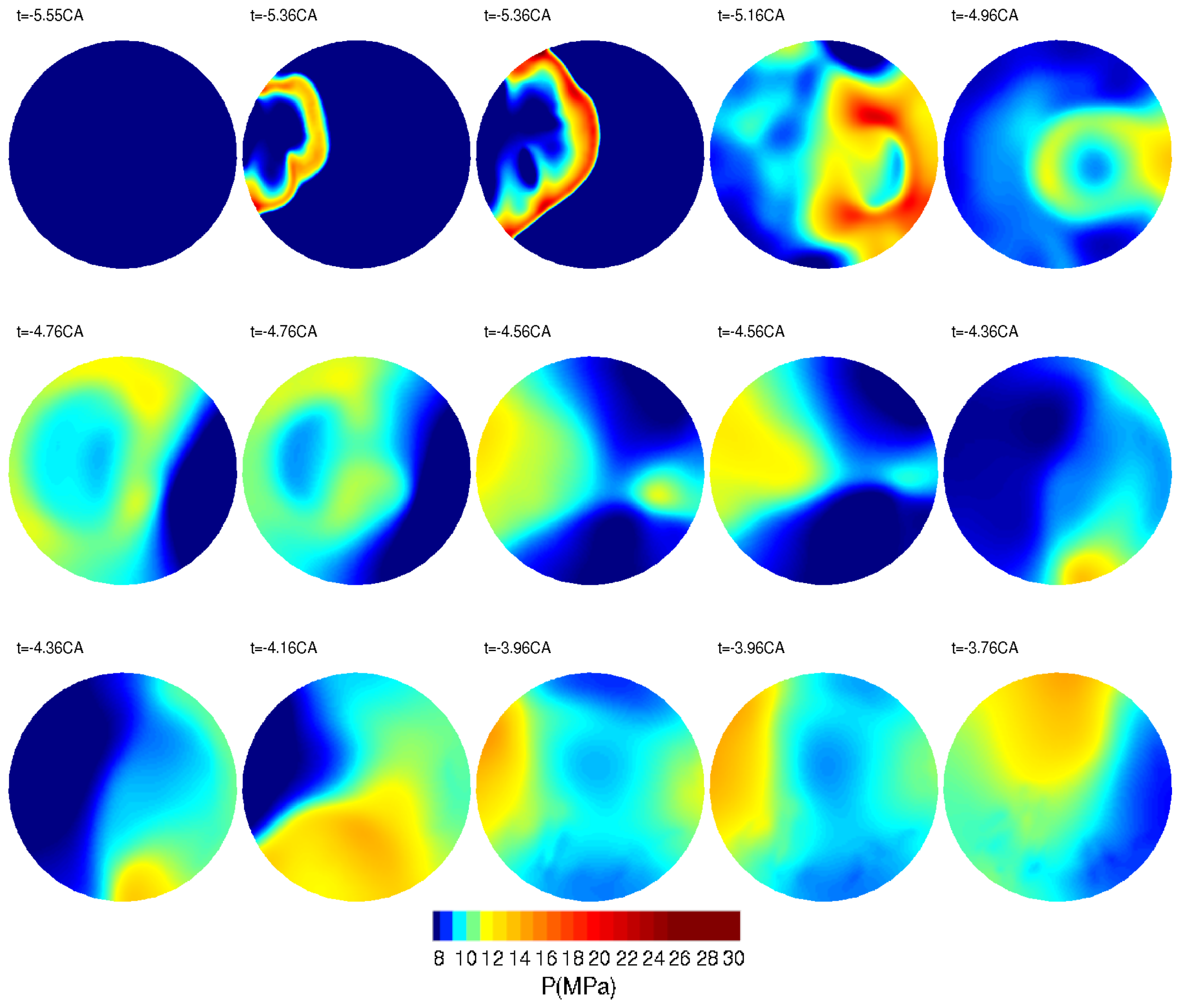
Figure 10 shows the pressure contours corresponding to the temperatures in Figure 9. In the first three frames, there is one clear pressure wave which is created by the dominant flame front in Figure 9. As the reaction spreads to the rest of the cylinder, the pressure peaks are no longer located where the temperature peaks are, indicating an interaction between waves emanating from different reaction zones.
5. Summary and Conclusions
The current study shows the early stages in developing a novel combustion technology which could be used in HALE drones, using hydrogen rich reforming products in order to reach higher altitudes without significant added weight. This in addition to the improved efficiency and combustion control possible with RefCCI engines.
RANS and LES simulations were performed coupled with GT-Power on an RefCCI engine. The engine configuration and operating conditions were set using GT-Power, and the 1D simulation results were also compared to the CFD predictions. The additional 3D considerations significantly change the outcome of the simulations. In the LES, heat release occurs first, followed by the RANS simulation and then the 1D model. This demonstrates the importance of stratification both of temperature and fuel composition to accurately predict ignition timing, which affect PRR and HRR as well. The LES results captured in some detail the interaction of pressure waves during combustion and their relation to the flame, a phenomena which cannot be predicted using RANS modeling.
The SAGE model used in the CFD simulations is especially suitable to HCCI combustion [6], since the combustion regime is close to homogeneous combustion, unlike the validation case of a partially premixed flame. The effects of stratification of temperature which control combustion in the RefCCI engine are different than those which occur on the sub-grid scales of the partially premixed flame. The SAGE combustion model is able to capture the species and flame structure of DME combustion, and is suitable for simulating homogeneous combustion. The additional effects of 3D modeling and turbulence considerations in the RefCCI engine resulted in different pressure and heat release traces, and should be considered when wanting to achieve predictive modeling. Comparing LES to RANS results in the engine flow validation section and the RefCCI showed the advantage of LES when simulating mixture propagation, which is important when modeling stratified charge combustion.
6. Further Research
Further research of RefCCI will include experimental validation of the numerical setup, currently being done at the Technion. LES results require statistics over several cycles, to evaluate combustion instabilities and cycle to cycle variation. Using the validation, optimal piston geometries, injector configurations, EGR levels and more can be determined. The 3D simulations can provide insights to the effects of flow and turbulence, as well as complex chemical processes in DME/H combustion.
An important aspect of engine development which was not included in the scope of this study is emissions, specifically formaldehyde from DME combustion [28]. A predictive simulation of emissions will require separate, validated models or very high-resolution simulations with large chemical kinetic mechanisms [30].
Author Contributions
Conceptualization, L.T. and S.H.F.; Methodology, S.H.F.; Validation, G.F.; Resources, S.H.F.; Writing—Original Draft Preparation, G.F.; Writing—Review & Editing, L.T.; Visualization, G.F.; Supervision, S.H.F. and L.T.; Funding Acquisition, L.T.
Funding
This research was funded by the Israel Science Foundation, grant number 2054/17.
Conflicts of Interest
The authors declare no conflict of interest.
References
- Mikulski, M.; Bekdemir, C. Understanding the role of low reactivity fuel stratification in a dual fuel RCCI engine—A simulation study. Appl. Energy 2017, 191, 689–708. [Google Scholar] [CrossRef]
- Tartakovsky, L.; Gutman, M.; Mosyak, A. Energy Efficiency: Methods, Limitations and Challenges. In Energy Efficiency of Road Vehicles—Trends and Challenges; Nova Science Publishers: New York, NY, USA, 2012; pp. 63–90. [Google Scholar]
- Verhelst, S.; Wallner, T. Hydrogen-fueled internal combustion engines. Prog. Energy Combust. Sci. 2009, 35, 490–527. [Google Scholar] [CrossRef]
- Inagaki, K.; Fuyuto, T.; Nishikawa, K.; Nakakita, K.; Sakata, I. Dual-Fuel PCI Combustion Controlled by in-Cylinder Stratification of Ignitability; SAE Technical Paper 2006-01-0028; SAE International: Warrendale, PA, USA, 2006. [Google Scholar]
- Kokjohn, S.L.; Hanson, R.M.; Splitter, D.; Reitz, R. Fuel reactivity controlled compression ignition (RCCI): A pathway to controlled high-efficiency clean combustion. Int. J. Engine Res. 2011, 12, 209–226. [Google Scholar] [CrossRef]
- Reitz, R.D.; Duraisamy, G. Review of high efficiency and clean reactivity controlled compression ignition (RCCI) combustion in internal combustion engines. Prog. Energy Combust. Sci. 2015, 46, 12–71. [Google Scholar] [CrossRef]
- Li, J.; Yang, W.; Zhou, D. Review on the management of RCCI engines. Renew. Sustain. Energy Rev. 2017, 69, 65–79. [Google Scholar] [CrossRef]
- Nazemi, M.; Shahbakhti, M. Modeling and analysis of fuel injection parameters for combustion and performance of an RCCI engine. Appl. Energy 2016, 165, 135–150. [Google Scholar] [CrossRef]
- Rahnama, P.; Paykani, A.; Reitz, R.D. A numerical study of the effects of using hydrogen, reformer gas and nitrogen on combustion, emissions and load limits of a heavy duty natural gas/diesel RCCI engine. Appl. Energy 2017, 193, 182–198. [Google Scholar] [CrossRef]
- Haworth, D.; Jansen, K. LES on Unstructured Deforming Meshes: Towards Reciprocating IC Engines; General Motors Research Labs.: Warren, MI, USA, 1996. [Google Scholar]
- He, C.; Leudesdorff, W.; di Mare, F.; Sadiki, A.; Janicka, J. Analysis of In-cylinder Flow Field Anisotropy in IC Engine using Large Eddy Simulation. Flow Turbul. Combust. 2017, 99, 353–383. [Google Scholar] [CrossRef]
- Di Sarli, V.; Benedetto, A.D. Sensitivity to the presence of the combustion submodel for large eddy simulation of transient premixed flame—Vortex interactions. Ind. Eng. Chem. Res. 2012, 51, 7704–7712. [Google Scholar] [CrossRef]
- Tartakovsky, L.; Sheintuch, M. Fuel reforming in internal combustion engines. Prog. Energy Combust. Sci. 2018, 67, 88–114. [Google Scholar] [CrossRef]
- Poran, A.; Tartakovsky, L. Performance and emissions of a direct injection internal combustion engine devised for joint operation with a high-pressure thermochemical recuperation system. Energy 2017, 124, 214–226. [Google Scholar] [CrossRef]
- Poran, A.; Thawko, A.; Eyal, A.; Tartakovsky, L. Direct injection internal combustion engine with high-pressure thermochemical recuperation—Experimental study of the first prototype. Int. J. Hydrogen Energy 2018, 43, 11969–11980. [Google Scholar] [CrossRef]
- Eyal, A.; Tartakovsky, L. Reforming Controlled Homogenous Charge Compression Ignition—Simulation Results; SAE Technical Paper 2016-32-0014; SAE International: Warrendale, PA, USA, 2016. [Google Scholar]
- Eyal, A. Reforming-controlled HCCI process. In Proceedings of the 6th International Conference on UAV Propulsion Technologies, Haifa, Israel, 26 January 2017. [Google Scholar]
- Richards, K.J.; Pomraning, E. CONVERGE (v2.4); Convergent Science: Madison, WI, USA, 2017. [Google Scholar]
- Senecal, P.K.; Pomraning, E.; Richards, K.J.; Briggs, T.E.; Choi, C.Y.; McDavid, R.M.; Patterson, M.A. Multi-Dimensional Modeling of Direct-Injection Diesel Spray Liquid Length and Flame Lift-Off Length Using CFD and Parallel Detailed Chemistry; SAE Technical Paper 2003-01-1043; SAE International: Warrendale, PA, USA, 2003. [Google Scholar]
- Curran, H.J.; Fisher, E.M.; Glaude, P.A.; Marinov, N.M.; Pitz, W.J.; Westbrook, C.K.; Layton, D.W.; Flynn, P.F.; Durrett, R.P.; zur Loye, A.O.; et al. Detailed Chemical Kinetic Modeling of Diesel Combustion with Oxygenated Fuels; SAE Technical Paper 2001-01-0653; SAE International: Warrendale, PA, USA, 2001. [Google Scholar]
- Fuest, F.; Magnotti, G.; Barlow, R.; Sutton, J. Scalar structure of turbulent partially-premixed dimethyl ether/air jet flames. Proc. Combust. Inst. 2015, 35, 1235–1242. [Google Scholar] [CrossRef] [Green Version]
- Coriton, B.; Zendehdel, M.; Ukai, S.; Kronenburg, A.; Stein, O.T.; Im, S.K.; Gamba, M.; Frank, J.H. Imaging measurements and LES-CMC modeling of a partially-premixed turbulent dimethyl ether/air jet flame. Proc. Combust. Inst. 2015, 35, 1251–1258. [Google Scholar] [CrossRef] [Green Version]
- Salazar, V.M.; Kaiser, S.A. An optical study of mixture preparation in a hydrogen-fueled engine with direct injection using different nozzle designs. SAE Int. J. Engines 2009, 2, 119–131. [Google Scholar] [CrossRef]
- Salazar, V.; Kaiser, S. Influence of the flow field on flame propagation in a hydrogen-fueled internal combustion engine. SAE Int. J. Engines 2011, 4, 2376–2394. [Google Scholar] [CrossRef]
- Scarcelli, R.; Wallner, T.; Matthias, N.; Salazar, V.; Kaiser, S. Mixture formation in direct injection hydrogen engines: CFD and optical analysis of single-and multi-hole nozzles. SAE Int. J. Engines 2011, 4, 2361–2375. [Google Scholar] [CrossRef]
- Woschni, G. A Universally Applicable Equation for the Instantaneous Heat Transfer Coefficient in the Internal Combustion Engine; SAE Technical Paper 670931; SAE International: Warrendale, PA, USA, 1967. [Google Scholar]
- O’Rourke, P.; Amsden, A. Implementation of a Conjugate Residual Iteration in the KIVA Computer Program; Technical Report; Los Alamos National Lab.: Santa Fe, NM, USA, 1986. [Google Scholar]
- Cung, K.; Moiz, A.A.; Zhu, X.; Lee, S.Y. Ignition and formaldehyde formation in dimethyl ether (DME) reacting spray under various EGR levels. Proc. Combust. Inst. 2017, 36, 3605–3612. [Google Scholar] [CrossRef]
- Arcoumanis, C.; Bae, C.; Crookes, R.; Kinoshita, E. The potential of di-methyl ether (DME) as an alternative fuel for compression-ignition engines: A review. Fuel 2008, 87, 1014–1030. [Google Scholar] [CrossRef] [Green Version]
- Gao, J.; Grover, R.O.; Gopalakrishnan, V.; Diwakar, R.; Elwasif, W.; Edwards, K.D.; Finney, C.E.; Whitesides, R. Steady-state Calibration of a Diesel Engine in CFD using a GPU-based Chemistry Solver. In Proceedings of the ASME 2017 Internal Combustion Engine Division Fall Technical Conference, Seattle, WA, USA, 15–18 October 2017; p. V002T06A025. [Google Scholar]
Figure 1.
Comparison of LES/FGM and LES/SAGE computed and experimental radial profiles of the mean and RMS of axial velocity and temperature.
Figure 1.
Comparison of LES/FGM and LES/SAGE computed and experimental radial profiles of the mean and RMS of axial velocity and temperature.

Figure 2.
Comparison of mean velocity and temperature results from RANS and LES simulations for SAGE and FGM combustion models.
Figure 2.
Comparison of mean velocity and temperature results from RANS and LES simulations for SAGE and FGM combustion models.

Figure 3.
mass fraction distribution at CA, .
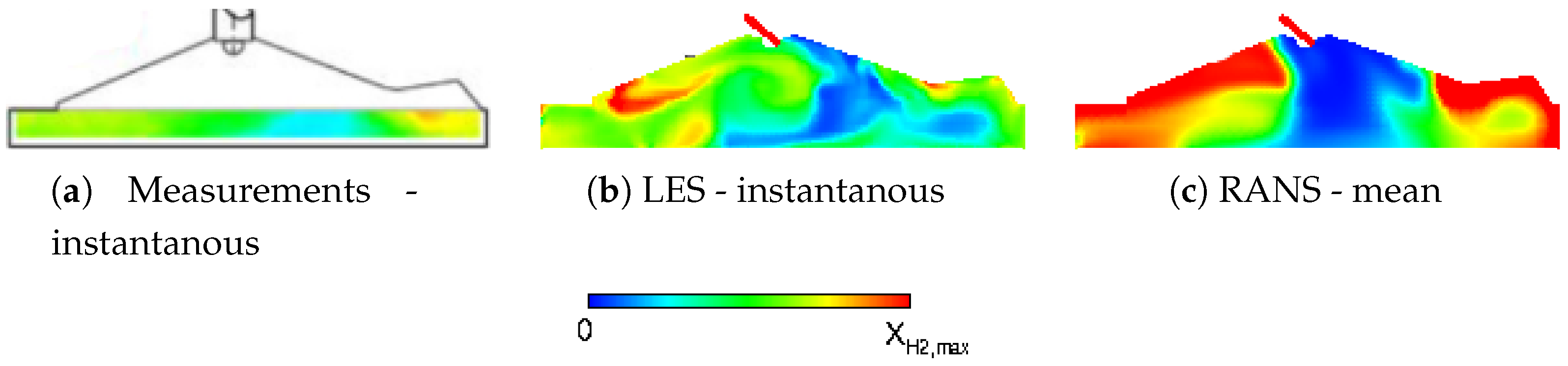
Figure 4.
The RefCCI engine model in GT-Power [17].
Figure 4.
The RefCCI engine model in GT-Power [17].

Figure 5.
(Left) geometry of the RefCCI engine used in the CFD simulation. (Right) slice rendition of the mesh during injection.
Figure 5.
(Left) geometry of the RefCCI engine used in the CFD simulation. (Right) slice rendition of the mesh during injection.

Figure 6.
Pressure trace and heat release rate (HRR) comparison of 1D GT-Power model to 3D CFD simulations.
Figure 6.
Pressure trace and heat release rate (HRR) comparison of 1D GT-Power model to 3D CFD simulations.

Figure 7.
Temperature and fuel stratification before the early heat release stage (t = −24CA), left to right: DME mass fraction, reformate mass fraction and temperature distributions in a slice view of the piston bowl.
Figure 7.
Temperature and fuel stratification before the early heat release stage (t = −24CA), left to right: DME mass fraction, reformate mass fraction and temperature distributions in a slice view of the piston bowl.

Figure 8.
Temperature and fuel stratification in the early heat release stage (t = −18CA), left to right: DME mass fraction, reformate mass fraction and temperature distributions in a slice view of the piston bowl.
Figure 8.
Temperature and fuel stratification in the early heat release stage (t = −18CA), left to right: DME mass fraction, reformate mass fraction and temperature distributions in a slice view of the piston bowl.

Figure 9.
Temperature contours during ignition in a slice of the piston bowl.

Figure 10.
Pressure contours during ignition in a slice of the piston bowl.


Table 1.
DI-H2ICE Engine Specifications.
| Bore | 92 mm |
| Stroke | 85 mm |
| Displacement | 565 cm |
| Compression ratio | 11 |
| Speed | 1500 rpm |
| Intake pressure/Temperature | 1 bar/36 C |
| Intake valve timing | open: 346CA / close: −140CA |
| Exhaust valve timing | open: 130CA/ close: −356CA |
| High pressure direct injection | |
| Injection pressure | 25 bar |
| Nominal Start of injection | −137CA |
| Actual Start of injection | −134CA |
| Injection duration | 74.5CA |
| Maximum mass flow rate | 5 × 10 kg/s |
Table 2.
RefCCI Engine Specifications.
| Bore | 80 mm |
| Stroke | 73 mm |
| Displacement | 367 cm |
| Compression ratio | 16 |
| Speed | 2500 rpm |
| Intake pressure/Temperature | 1 bar/36 C |
| Intake valve timing | open: 28BTDC / close: 4BBDC |
| Exhaust valve timing | open: 38BBDC/ close: 4ATDC |
© 2018 by the authors. Licensee MDPI, Basel, Switzerland. This article is an open access article distributed under the terms and conditions of the Creative Commons Attribution (CC BY) license (http://creativecommons.org/licenses/by/4.0/).
Share and Cite
MDPI and ACS Style
Faingold, G.; Tartakovsky, L.; Frankel, S.H. Numerical Study of a Direct Injection Internal Combustion Engine Burning a Blend of Hydrogen and Dimethyl Ether. Drones 2018, 2, 23. https://doi.org/10.3390/drones2030023
AMA Style
Faingold G, Tartakovsky L, Frankel SH. Numerical Study of a Direct Injection Internal Combustion Engine Burning a Blend of Hydrogen and Dimethyl Ether. Drones. 2018; 2(3):23. https://doi.org/10.3390/drones2030023
Chicago/Turabian StyleFaingold, Galia, Leonid Tartakovsky, and Steven H. Frankel. 2018. "Numerical Study of a Direct Injection Internal Combustion Engine Burning a Blend of Hydrogen and Dimethyl Ether" Drones 2, no. 3: 23. https://doi.org/10.3390/drones2030023