
Spherical Indoor Coandă Effect Drone (SpICED): A Spherical Blimp sUAS for Safe Indoor Use

Engineering Product Development Pillar, Singapore University of Technology and Design (SUTD), 8 Somapah Road, Singapore 487372, Singapore
*
Author to whom correspondence should be addressed.
Drones 2022, 6(9), 260; https://doi.org/10.3390/drones6090260
Submission received: 29 July 2022
/
Revised: 9 September 2022
/
Accepted: 12 September 2022
/
Published: 18 September 2022
(This article belongs to the Section Drone Design and Development)
Abstract
:Even as human–robot interactions become increasingly common, conventional small Unmanned Aircraft Systems (sUAS), typically multicopters, can still be unsafe for deployment in an indoor environment in close proximity to humans without significant safety precautions. This is due to their fast-spinning propellers, and lack of a fail-safe mechanism in the event of a loss of power. A blimp, a non-rigid airship filled with lighter-than-air gases is inherently safer as it ’floats’ in the air and is generally incapable of high-speed motion. The Spherical Indoor Coandă Effect Drone (SpICED), is a novel, safe spherical blimp design propelled by closed impellers utilizing the Coandă effect. Unlike a multicopter or conventional propeller blimp, the closed impellers reduce safety risks to the surrounding people and objects, allowing for SpICED to be operated in close proximity with humans and opening up the possibility of novel human–drone interactions. The design implements multiple closed-impeller rotors as propulsion units to accelerate airflow along the the surface of the spherical blimp and produce thrust by utilising the Coandă effect. A cube configuration with eight uni-directional propulsion units is presented, together with the closed-loop Proportional–Integral–Derivative (PID) controllers, and custom control mixing algorithm for position and attitude control in all three axes. A physical prototype of the propulsion unit and blimp sUAS was constructed to experimentally validate the dynamic behavior and controls in a motion-captured environment, with the experimental results compared to the side-tetra configuration with four bi-directional propulsion units as presented in our previously published conference paper. An up to 40% reduction in trajectory control error was observed in the new cube configuration, which is also capable of motion control in all six Degrees of Freedom (DoF) with additional pitch and roll control when compared to the side-tetra configuration.
1. Introduction
The advancement of consumer sUAS technology in recent years has enabled many applications in indoor environments, such as inspections, surveillance, advertising, etc. Many of these applications utilised multicopter sUAS, mainly due to their high payload capacity, high manoeuvrability and simple mechanical construction. There are many sources of external disturbances for sUAS flights in an outdoor environment, such as strong wind gusts; therefore, in such an operating environment, a multicopter’s high manoeuvrability is essential for its stable and reliable operation. However, in an indoor environment, this high manoeuvrability is often unnecessary, while the other characteristics of a multicopter, such as its low flight endurance, high noise signature and high safety risks, are often undesirable as it is operating in close proximity with obstacles and humans. For example, according to an article by Airborne Drones [1], a consumer drone, such as the DJI Phantom 4 Pro [2], can produce noise levels of as high as 81 decibel, which is equivalent to loud highway traffic noise at a close range. Such high levels of noise can impede effective voice communications between nearby humans and cause significant annoyance and noise pollution, especially in an indoor environment, where the noise may be amplified due to reflections and echo.
Multicopter sUAS also present significant safety risks when operating in close proximity with humans due to their fast rotating propellers, as propeller injuries are the leading mechanism of drone-related injuries according to a study by Johnson et al. [3]. The safety risks associated with the use of a multicopter sUAS often lead to the deployment of safety measures through the physical isolation of nearby humans from the sUAS in operation. This causes inefficiencies in the workspace usage and the low concurrency in applications where the workers may have to wait to carry out work in the same workspace. The safety risks, together with the low flight endurance of multicopter sUAS, also necessitate the employment of dedicated personnel for the operation of the sUAS, which increases the deployment costs of sUAS technology for various indoor applications.
Due to the dangerous nature of the multicopter sUAS when operating in close proximity with humans, there has been a lack of development and applications involving drone–human interactions or cooperation, except for very lightweight drones of around 20 g in mass. As such, the development of a new type of sUAS suitable for operation around humans in an indoor environment may create opportunities in novel applications such as advertising, entertainment, inspection, security, etc.
A blimp is a type of airship that relies on lifting gases such as helium to maintain its shape and buoyancy in air. Its lighter-than-air nature allows for it to ’float’ in the air, even in the case of total loss of propulsion power, and its gas-filled body, which takes up a large volume, has large aerodynamic drag, which makes its flight less dynamic and more predictable. These inherent properties of a blimp makes it significantly less dangerous for surrounding people compared to a multicopter sUAS with fast-spinning propellers, especially in an indoor environment.
1.1. Literature Review
Skye, a spherical omnidirectional blimp, introduced by M. Burri et al. [4], is capable of performing six Degrees of Freedom (DoF) motion with its four tetrahedral-arranged actuation units, which consists of a servomotor for rotation and a motor-driven propeller with a propeller guard. The mechanical complexity and design of the actuation units may suffer from damage upon impact and its 2.7 m diameter size is too large to be deployed in more confined spaces. The propeller guard may also be insufficient for reducing safety risks around people; for example, long hairs may be tangled in the fast spinning propellers if they happen to come into contact.
Similarly, the Halo drone from startup Spacial [5] is a blimp powered by side-mounted propellers that is designed for indoor aerial filming applications. Aerobots developed by I. Sharf et al. [6], a spherical blimp prototype for satellite emulation purposes, are powered by side-mounted electric ducted fans and capable of six DoF motion control. BalloonCam™ from Panasonic [7] was designed to have its quadcopter propellers hidden in the four vertical cutouts of its blimp envelope structure. All these designs are relatively large in size and the partially exposed propellers may pose cutting and entanglement hazards to nearby humans.
Festo has developed an extensive variety of lighter-than-air aerial robots over the years. The eMotionSpheres project [8] showcased multiple spherical blimps, propelled by side-mounted propellers, performing a precise and synchronized flight performance in an indoor environment. While FreeMotionHandling [9], another spherical blimp, has a pneumatic actuated gripper integrated into its helium gas envelope, both of these project showcased the versatility of a blimp platform in an indoor environment. However the utilisation of fast-spinning propellers on these blimps still poses some safety risks to surrounding humans and objects.
Inspired by various animals, such as penguin, manta ray, and jellyfish, Festo has also designed a series of aerial robots with a mechanical propulsion method through biomimicry. The AirPenguins [10] ’swims’ in the sea of air through the use of flapping wing mechanisms attached to the sides of the elongated spheroid envelope. The Air_ray [11] is shaped as a manta ray and mimics its movement through a flapping mechanism that is built into the blimp’s envelope, which allows for it to glide through the air, much like how manta rays swim in the sea. The AirJelly [12] is made up of a spherical envelope of 1.3 meter diameter, with eight mechanically actuated fins connected to the body through a tentacle-like flexible structure. Similar to how a jellyfish moves in water, the AirJelly propels itself upward by pushing air downwards through the mechanical flapping motion of the eight connected fins, while the lateral direction of the movement is controlled by a pendulum, which displaces the AirJelly’s center of mass. These mechanical propulsion methods based on biomimicry are fascinating to look at and generally safe to operate near humans due to the relatively slow motion of the flapping mechanisms. However, these flapping mechanisms are complex and built into the design of the blimp’s envelope, which may increase the costs of maintenance for such systems if deployed as an sUAS in an indoor environment. The ’swimming’ movement of these aerial blimps may also be less maneuverable, requiring a large turning radius to alter their direction of flight, which may make then unsuitable for applications with smaller flying spaces and one that requires precision flight control.
Aside from producing thrust using mechanical means, Poon et al. [13] have developed a noiseless and vibration-free propulsion technology for indoor surveillance blimps that utilized the ionic wind produced by an onboard ionic flyer for thrust. While a silent indoor blimp system is desirable, the high voltage nature of an ionic propulsion system makes it unsafe to be operated around human beings and objects that are sensitive to electrical discharge.
In the pursuit of a perfectly safe sUAS platform for close-proximity indoor use, Wataru et al. [14] have developed ZeRONE, a spherical blimp that utilizes piezoelectric microblowers to circumvent the use of a propeller for propulsion. The propulsion system constructed using arrays of piezoelectric microblowers is safe, silent and efficient; however, the generated thrust is weak and insufficient to propel the blimp to walking speed.
S-CLOUD, a torus-shaped blimp designed by Song et al. [15], has coaxial propellers placed in the hole of the torus envelope to produce vertical thrust. A two-axis, servomotor-controlled flap is placed below the propellers to deflect the downwards airflow to the side. The deflected airflow then attaches and follows the bottom curved surface of the torus envelope due to the Coandă effect, which results in lateral thrust. This approach is innovative in how it utilizes the curved surface on the torus-shaped helium gas envelope as a means to redirect airflow through the Coandă effect.
1.2. Contributions of This Work
In this paper, a novel propulsion and control method for indoor miniature spherical blimps called Spherical Indoor Coandă Effect Drone (SpiCED) is presented. The aim of the research is to develop a small unmanned aircraft system (sUAS) that is safe to operate in close proximity with humans in indoor spaces by replacing the propellers typically employed on blimps, sUAS [4,5,6,7,15], with a closed impeller design, which insulates the sharp and fast-spinning edges from the surroundings. Compared to Festo’s biomimicry aerial robots [10,11,12], the SpICED design is more maneuverable and can translate in any direction without a large turning radius. It is also safer than high-voltage ionic wind propulsion [13] and provides more thrust for higher moving speeds when compared to piezoelectric-microblowers-based propulsion [14]. The low-profile propulsion system on SpICED is made up of multiple Propulsion Units (PUs) with closed impellers that are directly driven by brushless DC motors, which provides a thrust force through the Coandă effect on the spherical body of the blimp.
The SpICED design is inherently safe as it is typically weightless due to the buoyancy of the helium gas. Even in a total loss of power, SpICED remains suspended in the air, as opposed to a crash, which can happen to a multicopter in such a scenario. The Blunt Criterion [16,17,18,19] calculated for a human adult male impacted at the chest by SpICED prototype at 1 m/s speed is -8.9; hence, there is zero probability of a minor injury in this case. The highest speed component of SpICED is the closed impeller, which has a very low profile with concealed sharp edges, minimizing any risk of injury.
In a previously published conference paper [20], we introduced a version of this indoor blimp sUAS with four bi-directional PUs and proved the controllability of the sUAS with experimental results. In this paper, we are exploring a new configuration of the design, with eight uni-directional PUs, for better maneuverability and control response.
Our contributions in this paper are as follows:
- The introduction of a uni-directional Propulsion Unit (PU) made up of a closed impeller with curved vanes, and eacomparison between the uni-directional PU and the bi-directional PU with straight vanes, as presented in the previous paper [20].
- The introduction of the cube configuration propulsion system with eight PUs, which eliminates the need for bi-directional PU as compared to the other configurations.
- Experimental results of both the uni-directional PU’s performance and the closed-loop flight control of the blimp sUAS prototype with cube configuration, with a comparison to the prebiously explored side-tetra configuration.
2. Design of SpICED
2.1. Design of the Propulsion Unit (PU)
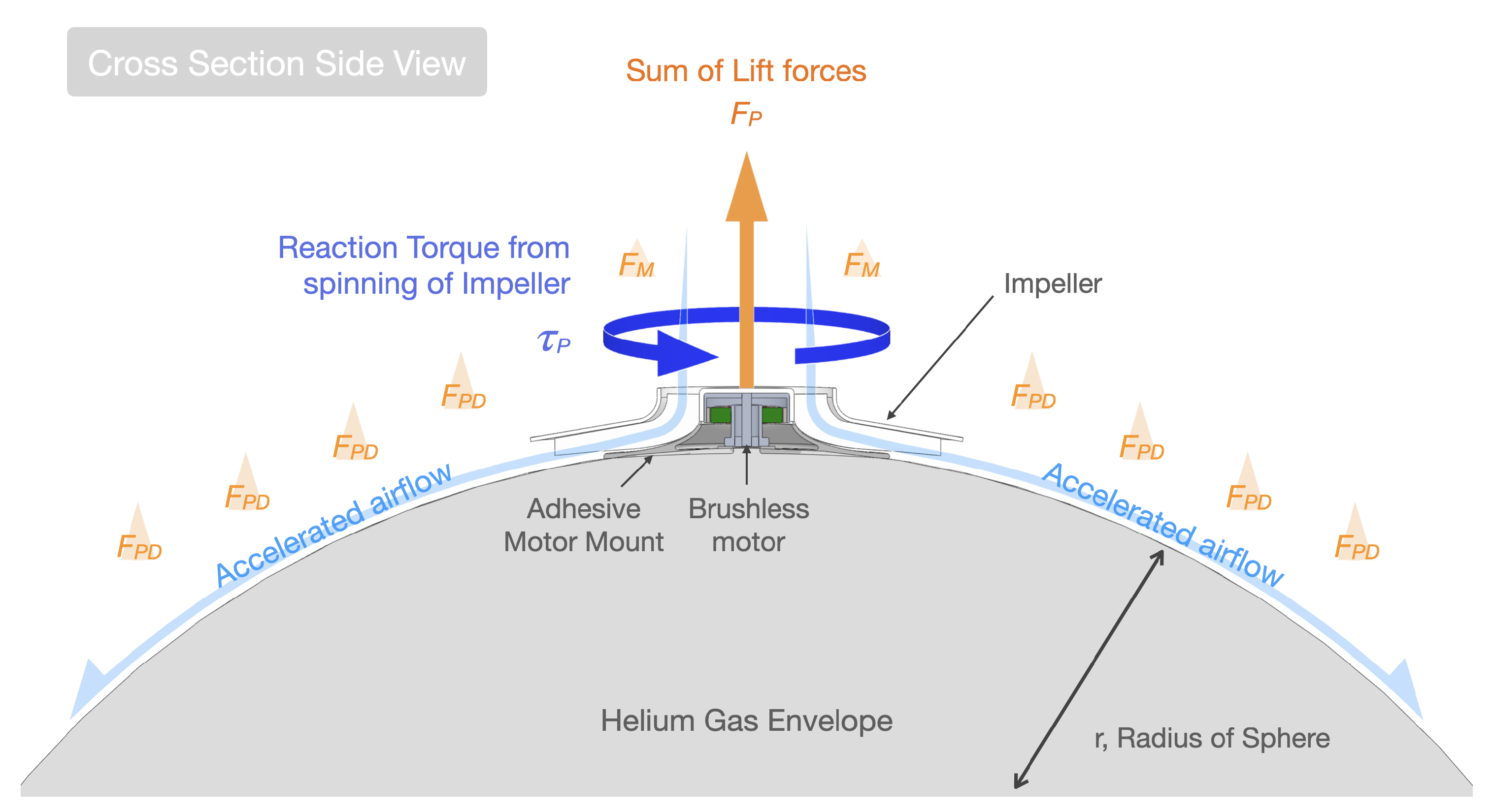
The proposed blimp design is propelled by PUs on the blimp’s surface, which directly accelerate airflow along the surface of the spherical blimp. The accelerated airflow sticks to the curved surface of the spherical body due to the Coandă effect. This creates a lower air pressure above the surface and produces aerodynamic lift on the blimp body. The spherical shape of the blimp envelope is chosen so that Coandă effect is equally produced in all radial directions.
As illustrated in Figure 1, each PU is made up of a closed impeller, attached to the rotor of a DC electric brushless motor, with the motor’s base attached to a mounting plate that allows for the PU to be affixed to the surface of the blimp with the use of adhesive. The electric brushless motor spins up the impeller, which, in turn, draws in air from the inlet of the impeller and ejects the accelerated airflow radially outwards over the surface of the blimp. Aside from the lift forces produced by the accelerated airflow, the rotation of the rotor and impeller produces a reaction torque on the blimp body to which the motor’s base is attached. This reaction torque can be utilised to manipulate the orientation of the blimp in flight.
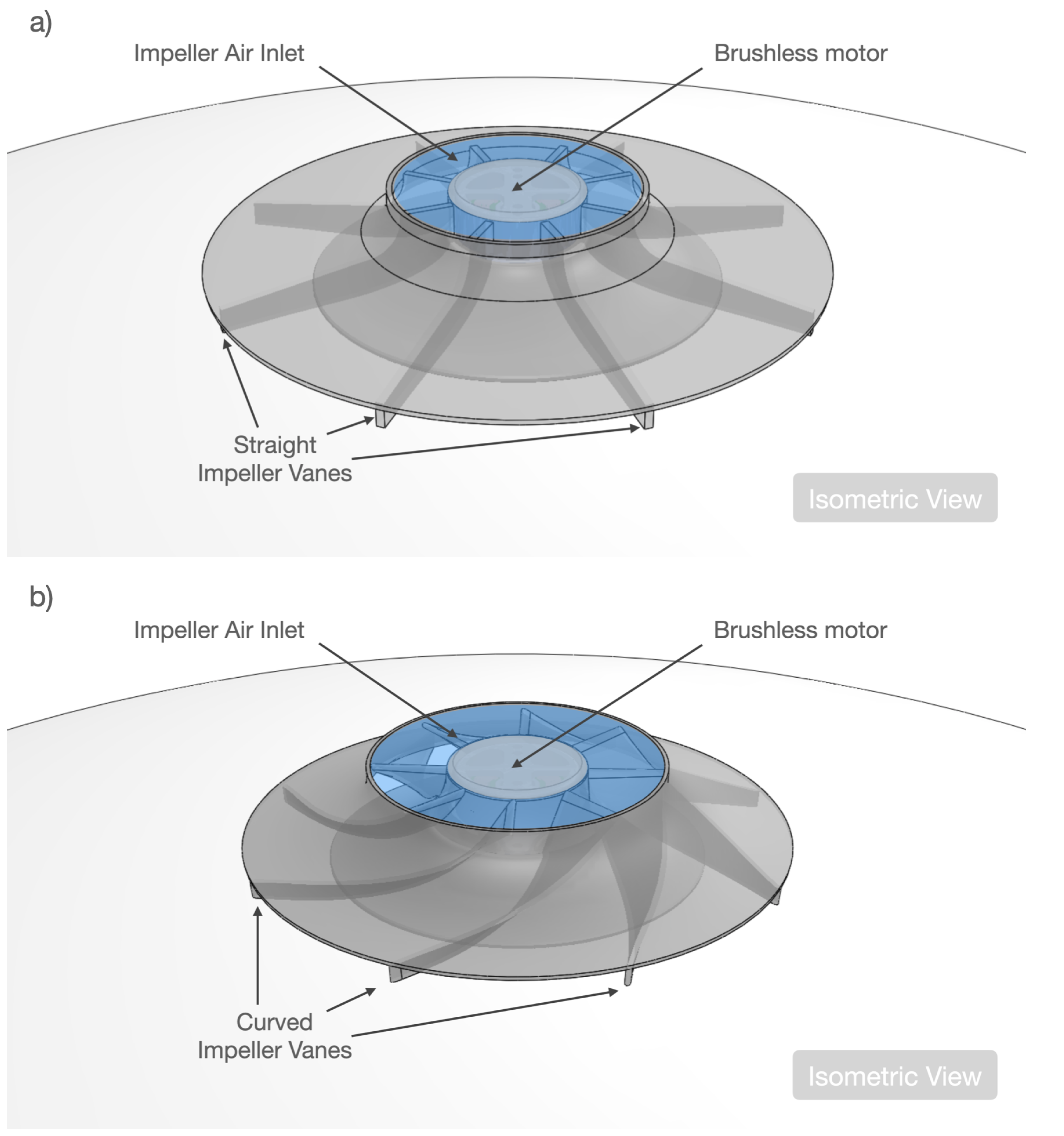
Figure 2a shows an impeller design with symmetrical straight radial vanes; although this is less efficient compared to a backward-curved vane impeller, it has an identical performance in both directions of rotation. This allows for the reaction torque from the spinning impeller to be utilized to control the blimp’s orientation, without placing the PUs in a counter-rotating pair arrangement. In a straight vane impeller, the thrust direction remains the same regardless of the direction of rotation. This PU with a straight vane impeller will be called the bi-directional PU.
Figure 2b shows an impeller design with curved impeller vanes. The design is modelled with the assistance of turbomachinery software, with parameters to improve efficiency and performance compared to the straight vane impeller; however, the non-symmetrical nature of this impeller design does not produce the same amount of thrust if rotated in the opposite direction. Thus, it is designed to only spin and produce torque in a single direction, and more PUs with this impeller may be required for orientation control of the blimp in flight. A PU with this curved vane impeller will be called a uni-directional PU.
As stated by R. I. Ahmed et al. [21] in their investigation into the aerodynamics of a Coandă effect Micro Aerial Vehicle (MAV), the total lift forces generated by the Coandă effect blanket on a semi-spherical Coandă effect MAV is as follows:
where stands for the net thrust, stands for vertical lift forces due to the momentum balance of the Coandă blanket and stands for the lift forces due to pressure difference on the MAV body subject to the Coandă blanket, as shown in Figure 1. In our aerodynamics considerations in this work, we assume that the thrust and torque produced by the PU, and , are proportional to the square of rotational speed, . and , are approximated as follows for our dynamic model, with reference to [22]:
where is the impeller thrust coefficient and is the impeller drag coefficient, both of which are empirically found in the experimental investigations in Section 3.3. The assumption that and are proportional to is also validated with empirical findings, as shown in Section 4.1.1.
2.2. Multi-Unit Propulsion System Configurations
As each PU is only capable of producing thrust and torque along a single axis, it is necessary to deploy multiple PUs to achieve the necessary flight control for the blimp. The minimum flight control requirement for a typical blimp is the ability to translate in three-dimensional space and rotate about the yaw axis.
Several configurations for the placement of the PUs were considered and compared in Figure 3. It is generally better to choose a configuration that utilizes fewer PUs, as this reduces the total mass of the propulsion system, which, in turn, allows for a bigger portion of the mass budget to be allocated to the battery and payload. For translational motion in three-dimensional space, only the thrust component from the PU is necessary, while the reaction torque from the PU is required for the control of yaw; therefore, it will be favourable to position the PU to counter the reaction torques and avoid introducing unintended rotation when only thrust is required.
In the cube configuration shown in Figure 3a, there are eight PUs, the most in all of the considered configurations, and they are placed on the surface of the blimp at an equal distance from each other, with the position of the PUs forming a n internal cube. This configuration allows for the use of a non-symmetrical impeller design, as there are two counter-rotating PUs in all direction, so the unintended torque produced by a spinning impeller can be cancelled out by another adjacent impeller spinning in the opposite direction with the same speed. The large number of actuators also allows for this configuration to be controlled in all six DoFs with the addition of pitch and roll angle control. The extra controllable degree of freedom may allow for new use-cases, for example, control of the field of vision of a fixed mounted camera on the blimp. Out of all the considered configurations, this is the only one that does not contain any coupling between movements in all six DoF. However, a propulsion system with such a configuration will also be heavier and reduce the mass budget for other components, such as the battery.
In the prism configuration shown in Figure 3b, there are six PUs mounted in a counter-rotating manner, with the mounting position of the impellers forming an internal prism shape. The top and bottom group of PUs are mounted with an angle offset from the horizontal XY plane. The adjacent top and bottom PU pairs may work together in counter-rotation to cancel the net yaw moment while translating in a particular direction. However, it may be at a disadvantage as its yaw and altitude motions are coupled due to the odd number of PUs on the top and bottom.
In the pyramid configuration shown in Figure 3c, there are five PUs in total, with four of the PUs mounted on the bottom hemisphere of the blimp, facing to the sides and slightly downwards by the angle . The four bottom PUs form the base of the pyramid shape and the fifth PU is placed on top and aligned with the Z axis of the blimp body, to form the peak in the pyramid shape. This configuration has an odd number of PUs on the top and an even number on the bottom. This means that its ascending motion is coupled with yaw, whereas the descending motion is decoupled from yaw. Its lateral translational motions are mildly coupled with both altitude and yaw, but this can easily be solved by the use of a feedback controller.
The tetrahedron configuration shown in Figure 3d is similar to the pyramid configuration in Figure 3c, except that it has four PUs in total, with only three PUs forming the internal base of the tetrahedron shape. This configuration utilizes the lowest number of PUs, with ab odd number of PUs for both the top and bottom, coupling the vertical motion with yaw. It has one less PU for lateral motion as compared to the pyramid configuration, which couples lateral motion with yaw control. Similarly, this coupling between lateral motion and yaw can be solved by the use of a feedback controller.
Lastly, a side-tetrahedron configuration with four PUs shown in Figure 3e is explored. The difference between the side-tetrahedron and tetrahedron configuration is the internal orientation of the shape, where the tetrahedron configuration has a horizontally aligned base, and the side-tetrahedron configuration has its edge on the bottom. This configuration has pairs of PUs mounted on both the top and bottom hemisphere and completely decouples vertical motion from yaw. It is mildly coupled for lateral motion and yaw, which can also be solved using a feedback controller.
The position coordinate of the PUs for each configuration can be found in Table 1.
2.3. System Dynamics and Control of Multi-Unit Propulsion Blimp
Out of the five propulsion system configurations described in Section 2.2, the side-tetrahedron configuration was investigated in our previous paper [20], with experimental results showing controllability, with only four PUs. In this paper, the cube configuration with the excess eight PUs is selected for analysis and comparison with the side-tetrahedron configuration.
As identified in our previous paper [20], the bi-directional PU requires the reversal of the rotational direction in flight for torque control in the side-tetrahedron configuration. However this reversal cannot be accomplished rapidly due to the rotational inertia of the impeller, which results in a lag time during rotational reversal that affects the control performance of the side-tetrahedron configuration. The arrangement of the PUs on the side-tetrahedron configuration also introduces coupling between different control axes; for example, when horizontal translation is required, only a single PU is activated, which produces torque that results in yaw deviation, which has to be corrected with other PUs. This complicates the control algorithm of the system and resulted in a prototype with a less-than-ideal control performance.
To address these control issues, the cube configuration utilizes uni-directional PUs, which do not required rotational reversal with the additional benefits of the higher thrust and efficiency of the curved-vane impeller. With two times the number of PUs compared to side-tetrahedron configuration, the cube arrangement of the PUs on the cube configuration allows for the PUs to work in counter-rotating pairs to cancel out each other’s torque, which eliminates the control coupling issue on the side-tetrahedron configuration. The additional number of PUs in the cube configuration also enable extra pitch and roll axes control, which was not present on the side-tetrahedron configuration.
The following subsections describes the blimp’s dynamic model for the cube configurations.
Dynamic Model of Cube Configuration
The cube configuration’s free body diagram is illustrated in Figure 4; the world frame is denoted as and the body frame . The PUs are mounted on the surface of the spherical blimp with the coordinates internally forming a cube with equal length edges, which means that each PU is mounted at an equal distance from adjacent PUs. The direction of rotation for each PU is the opposite of its adjacent PUs, meaning that, as P1 rotates counter-clockwise, its adjacent PUs (P2, P4 and P5) rotates in the clockwise direction. The blue rotation arrow on each of the PU shown in Figure 4 indicates its direction of rotation. Each of the PUs is capable of producing thrust and torque , as given in Equations (2) and (3), respectively.
As illustrated in Figure 4, P1, P3, P6 and P8 rotate in the counter-clockwise direction, and P2, P4, P5 and P7 rotate in the clockwise direction.
The batteries and electronics are mounted on both the top and bottom of the blimp’s body; thus, the CG of the blimp coincides with the geometric center of the blimp’s spherical body, with the lifting force of the helium gas directly acting on the CG, cancelling out the gravity force due to its neutral buoyancy. As there is no offset distance between the lifting force and gravity force, there is no restoring moment on the pitch and roll axes that are present in the side-tetrahedron configuration, and the blimp is free to rotate in all three axes. This is the property that allows for the pitch and roll angle to be controlled in this configuration. However, due to the mounting of heavy batteries on the top and bottom of the blimp, the moments of inertia for pitch and roll axes are significantly higher than the yaw axis.
The sum of forces and moments acting on the model can be summarized as follows:
Using Newton–Euler equations, the translational and rotational dynamics of the blimp can be written as follows:
where m is the mass of the blimp, is the moment of inertia of the blimp about its CG, and is the angular velocity of the blimp.
Compared to the side-tetrahedron configuration, the cube configuration differs in the position of its CG. The CG in the side-tetrahedron configuration is below the geometric center of its spherical blimp envelope due to the placement of its battery and electronics. The distance between the points of helium gases’ lifting force and gravity force causes a self-righting moment around the pitch and roll axes of the blimp. This difference is intentional, as the side-tetrahedron configuration is designed to be controllable in four DoF while the cube configuration is controllable in six DoF.
2.4. Closed Loop Control System
For the side-tetrahedron configuration, Proportional–Integral–Derivative (PID) controllers are only applied for each of the four controllable degrees of freedom, namely, X, Y, Z positions and yaw angle (), while the cube configuration has two additional controllable DoF, namely, the pitch () and roll () angle, as shown in Figure 5. The output from the controllers are fed into a unique control output mixer that maps the controller output to an actuator signal for each PU, .
2.5. Control Output Mixing for Cube Configuration
While the side-tetrahedron configuration utilizes PUs with a straight impeller, which is designed to rotate in both directions, for the cube configuration, it utilizes PUs with a curved vanes impeller, which, as mentioned in Section 2.1, is designed to only rotate in a single direction. Therefore, the rotation directions of the PUs are fixed, which simplifies the mixing algorithm as there is no need for PUs to switch their rotation direction. The mixing algorithm detailed below maps the controller output into different sets of PUs, depending on the control direction.
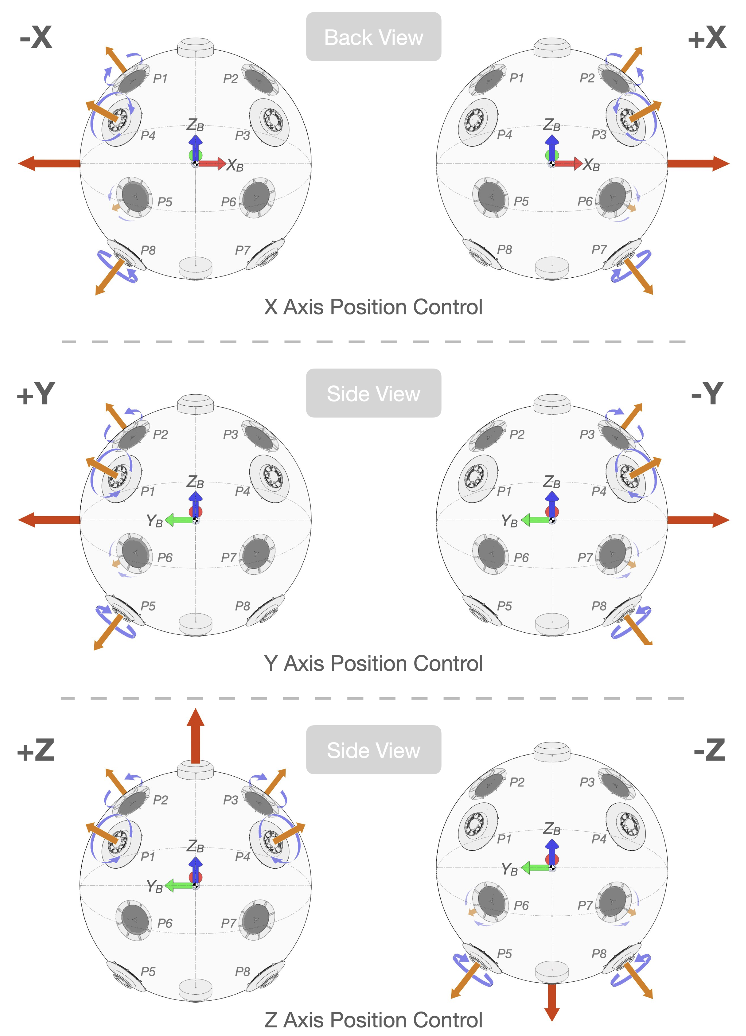
Figure 6 illustrates the specific PUs used to activate position control in the X, Y and Z axes. For movement in X, Y and Z axes, the four PUs on the hemisphere facing the direction of movement are simultaneously activated, with two sets of PUs each spinning in clockwise and counter-clockwise directions. For example, to move in the direction, P2 and P7 will spin in the clockwise direction while P3 and P6 will spin in the counter-clockwise direction. As a result, the PUs produced torques and forces, which are not aligned to the direction. These are cancelled out, leaving only the combined force vector in the direction.
Therefore, the X, Y and Z position control mixing is defined as follows:
where is the mixing gain for translational motion. max() and min() functions check whether the control signal is positive or negative. For example, if is negative, this indicates that the controller intends to go towards the negative Y direction, resulting in the activation of , , and . Note that the actuator signals are absolute values due to the fixed rotation direction of the PUs mentioned in Section 2.3.
Figure 7 illustrates the specific PUs used to activate attitude control in the Pitch (), Roll () and Yaw () axes. For attitude control, PUs with a torque direction that aligns with the intended direction of rotation in attitude are simultaneously activated. For example, to rotate the blimp in the direction around the Yaw axis, P2, P4, P6 and P8 are simultaneously activated to produce torque. Due to the location of these PUs, the thrust forces produced by the PUs cancel each other out. In this case, thrust produced by P2 is cancelled out by thrust produced by P8, and thrust produced by P4 is cancelled out by thrust produced by P6. Thus, only the torque produced from the PUs remains and rotates the blimp’s body around the Yaw axis.
Therefore, the Pitch (), Roll () and Yaw () position control mixing is defined as follows:
where is the mixing gain for rotational motion.
Finally, the control outputs from all the mixing algorithms are combined and sent as actuator commands to the eight PUs, as follows:
where .
The mixing gains and PID gains for the cube configuration are given in Table 2.
3. Prototype and Experimental Design
3.1. Propulsion Unit Prototype
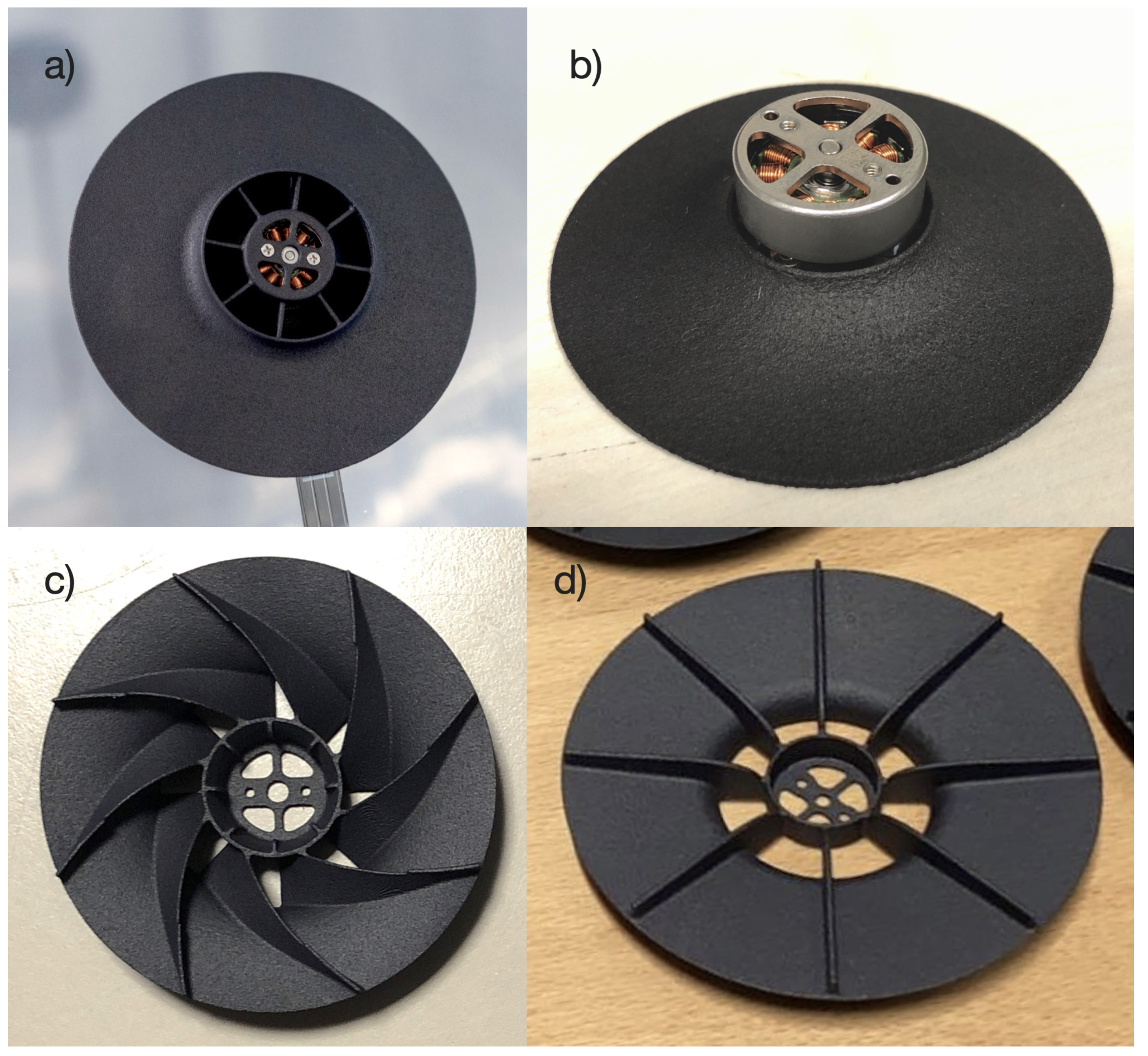
Figure 8 shows the prototype of the PU and its components. The DC brushless motor used in the construction of the PU prototype was an 18 mm diameter, 2900 rpm/V, outrunner DC brushless motor used in DJI’s Mavic Mini [23], a miniature quadcopter under 250 g weight. The motor was chosen due to its low mass of only 6.7 g; however, it is designed for spinning small, lightweight and fast spinning propellers, meaning that there is not enough torque to spin objects with a higher moment of inertia. This limitation means that the impeller design for the PU has to be lightweight and small in diameter to reduce its moment of inertia around the rotation axis. Figure 8c shows the curved vane impeller prototype with a diameter of 80 mm and Figure 8d shows the straight vane impeller prototype with a diameter of 90 mm. The impeller and motor mount prototypes were 3D-printed using HP’s Multi Jet Fusion [24] technology, with the PA12GB, a glass-bead-filled thermoplastic material, in order to reduce the thickness of the impeller shell to 0.6 mm while ensuring the rigidity of the parts.
The DC brushless motor in the PU was powered through a Flexible Printed Circuit (FPC) cable that contained the three wires for the three-phase power of the brushless motor. The FPC was routed under the base of the motor mount and adhered to the surface of the blimp’s envelope using double-sided adhesives. The use of a FPC is necessary to reduce the thickness of the wires coming out from the PU, which may disrupt the accelerated airflow along the surface produced by the spinning impellers.
3.2. Cube Prototype
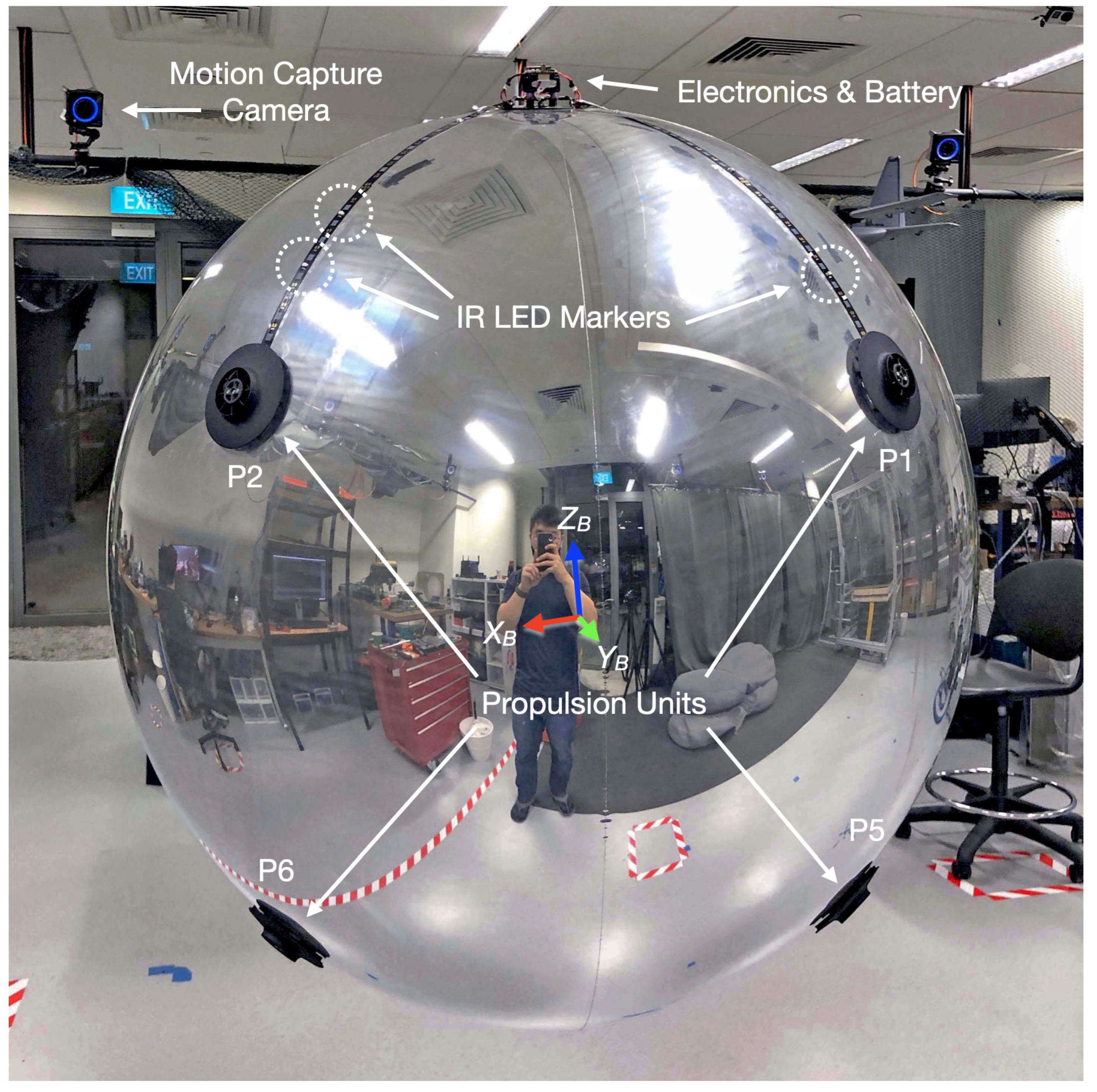
Figure 9 shows the SpICED prototype with the cube propulsion configuration. The foil balloon envelope used was the same as the side-tetrahedron prototype, which was fully inflated with helium gas into a spherical shape of around 80 cm in diameter, which contained around 0.268 m volume of helium gas. As helium gas’ lifting capability at sea level is 1.114 kg/m, the volume of helium gas contained in the envelope was capable of lifting around 298 g.
Two sets of identical propulsion systems were mounted on the top and bottom of the spherical blimp envelope, each set with four PUs, connected to the 4-in-1 Electronic Speed Controller (ESC) through a new FPC cable with integrated InfraRed (IR) LEDs as active IR motion tracking markers, as shown in Figure 10, as active markers for the motion capture system. Each propulsion system set also had its own custom-designed, flight-control Printed Circuit Board (PCB) unit and its own battery. The positioning of the PUs, with their connection to the electronics and battery, was in accordance with the coordinates mentioned in Table 1, and the layout illustrated in the free body diagram in Figure 4.
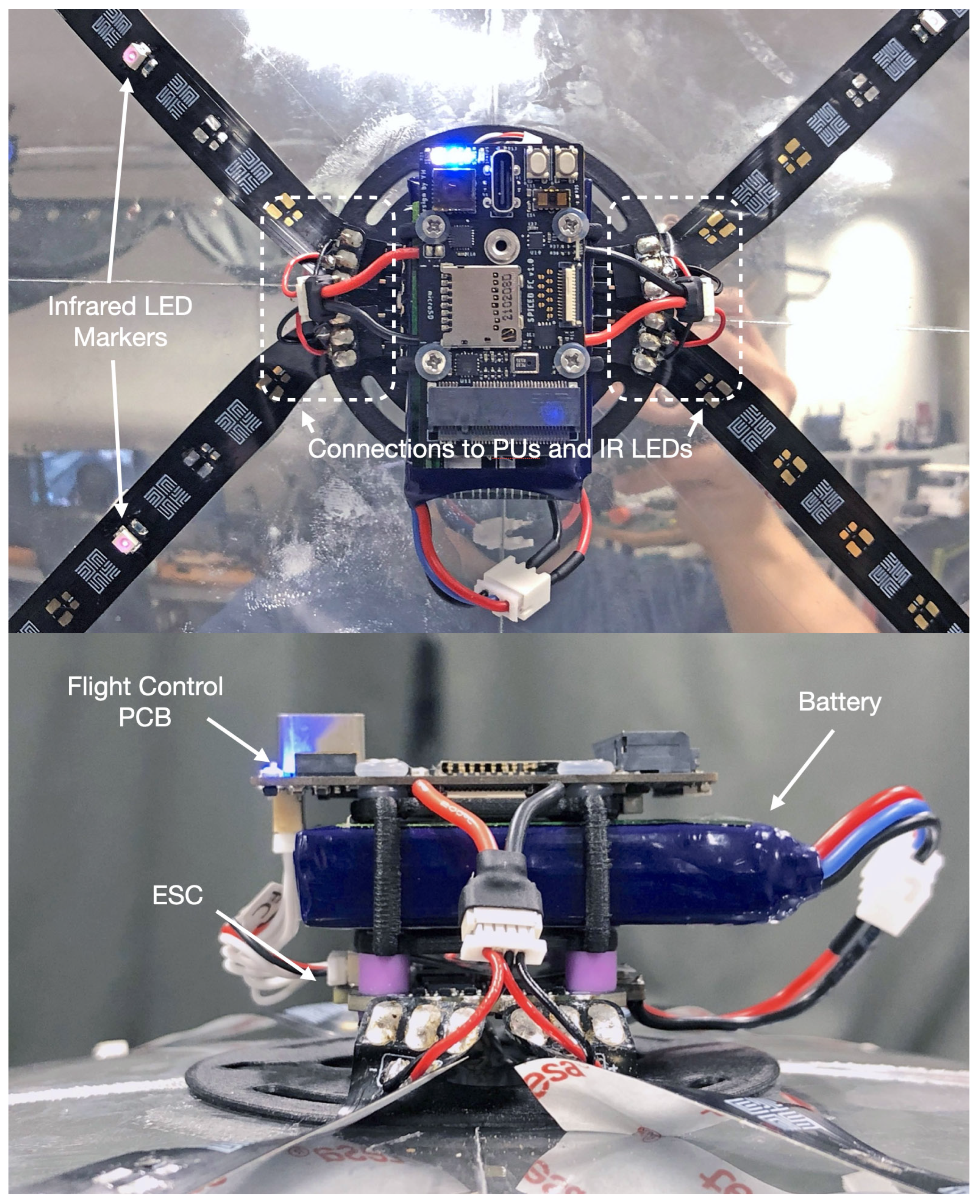
Figure 11 shows a custom, six-layer flight-control PCB that was designed to integrate power electronics, sensors and a WiFi-capable microcontroller for wireless communications and to process sensor data for flight control algorithms onboard the SpICED prototype.
Figure 12 shows the electronics system mounted on the SpICED prototype, together with the location of main components, such as the battery, ESC, and their connection to the PUs through the FPC cables, with the infrared LEDs used as active markers for the motion capture system. Table 3 shows the breakdown of the weights of different systems and components onboard the SpICED (Cube) prototype.
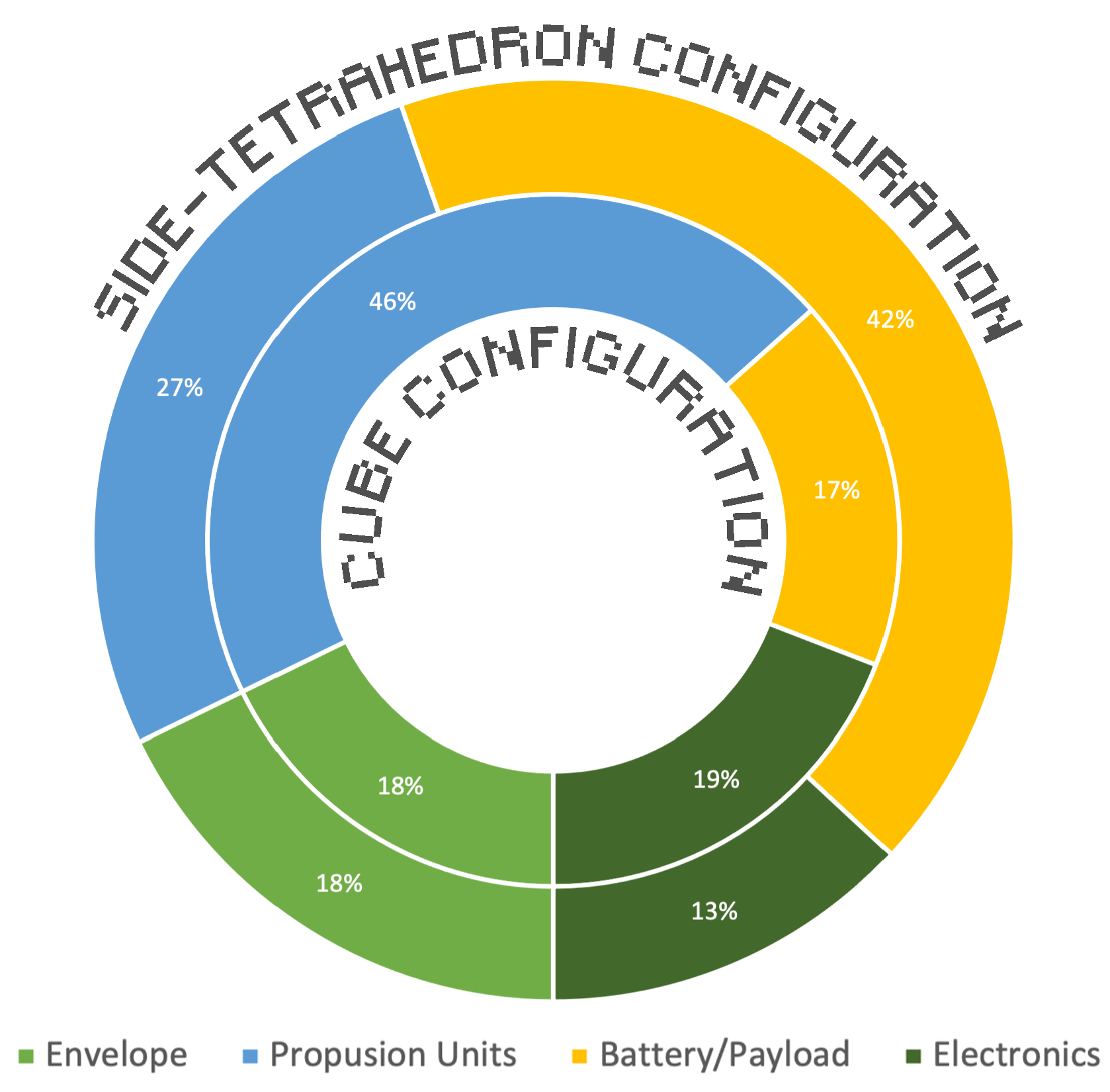
A comparison of the mass distribution to the side-tetrahedron prototype is shown in Figure 13. Due to the lower number of PUs in the side-tetrahedron configuration, the mass proportion of PUs and electronics was 19% and 6% less compared to the cube configuration, while the battery/payload capacity was 25% more compared to the cube configuration.
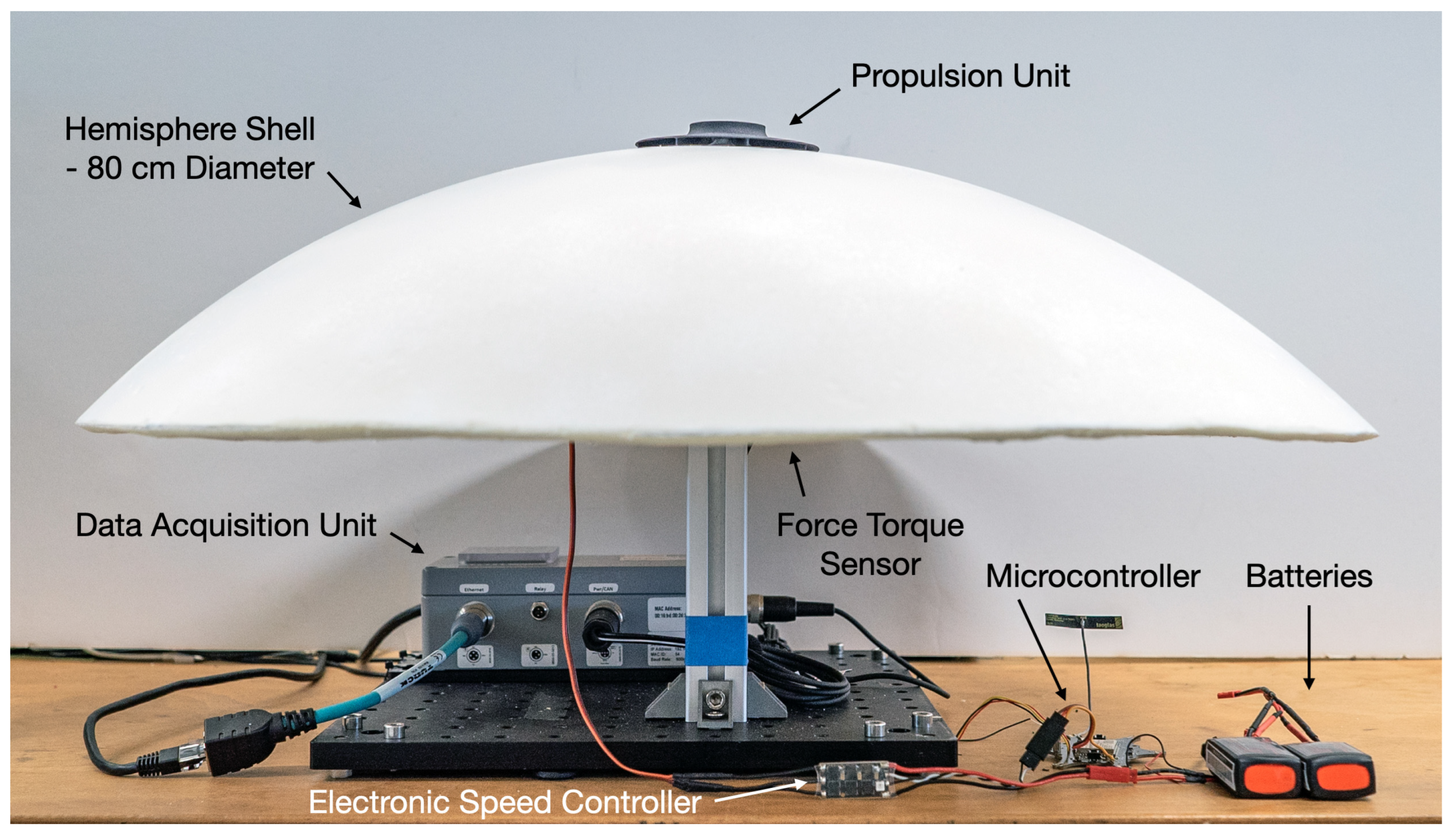
3.3. Propulsion Unit Performance Measurement Setup
The performance of the PU was measured using the set-up shown in Figure 14, with the RPM, force and torque of the PU being measured and recorded. The hemisphere shell utilised in the setup was produced by filling an acrylic hemisphere mold with polyurethane self-expanding foam. An ATI Nano43 force-torque sensor was attached under the hemisphere shell using double-sided adhesive to measure the force and torque produced by the PU. The rotational speed of the impeller was measured using the ESC by measuring the back electromotive force produced by the spinning of the DC brushless motor. The first test consisted of a program that cycles between 10 levels of throttle from 0–100% in order to measure the relationship between the the rotational speed of the impeller and the force and torque produced by the PU.
3.4. Closed-Loop Control Experiment Setup
Figure 15 shows the electronics and control system diagram implemented on the SpICED prototype system. The onboard electronics and control system consisted of four sets of DC brushless motors in the PUs, each controlled by an ESC that receives power from a two-cell Lithium Polymer battery, with throttle signals directly received from an onboard radio control receiver/WiFi. For the SpICED prototype with the cube configuration, there were two identical sets of onboard electronics and power systems, as mentioned in Section 3.2.
The position of the blimp was captured using an infrared motion capture system, and fed into the control loop code in Figure 5 running on MATLAB on an external PC connected to the motion capture cameras. The computed output of the PID controllers was then passed through a mixer algorithm, which converts it to the throttle value for each of the PU. Finally, the throttle signal was sent to the SpICED prototype through the radio control transmitter module/WiFi. Subsequently, the throttle signals that were received were sent to the individual ESCs, which control the rotation speed of the individual PUs.
4. Experiment Results
4.1. Performance Results of Propulsion Unit Prototypes
As we discovered in the previous paper, the bi-directional PUs with straight vane impellers used on the side-tetrahedron prototype produce symmetrical thrust and torque in both clockwise and counter-clockwise rotations. However they had a poor transient response when their rotational direction was reversed due to the low-torque DC brushless motor that was utilized and the increased moment of inertia of the impeller as compared to the lightweight propeller that the motor was designed to drive. Therefore, by utilizing more PUs with fixed rotation directions on the cube configuration, we are interested in comparing the performance of the bi-directional PUs and the uni-directional PUs.
4.1.1. Uni-Directional Propulsion Unit with Curved Vane Impeller
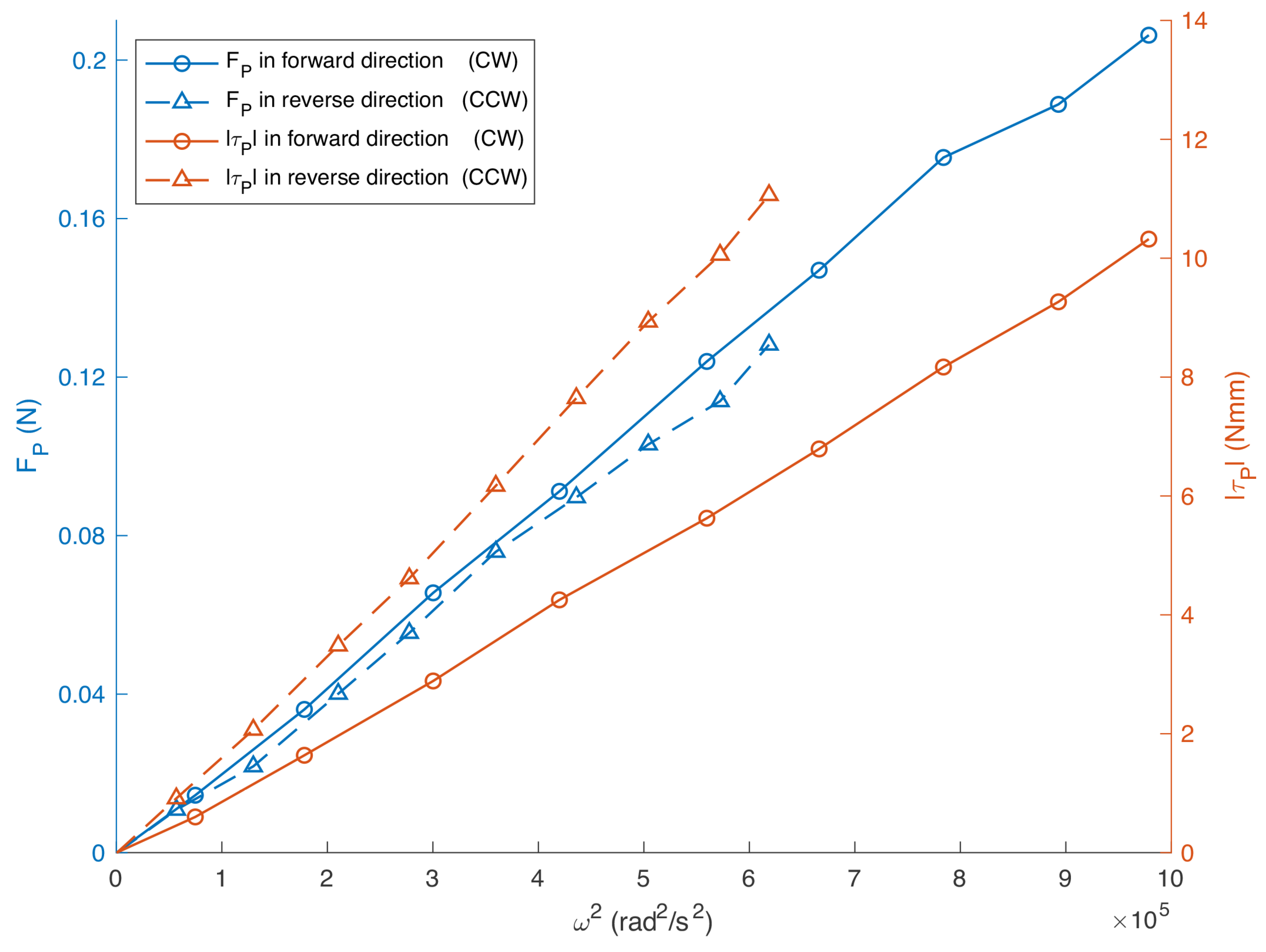
As the uni-directional PU is equipped with a curved vane impeller, the thrust and torque performance of forward and reverse rotation directions differed.
Figure 16 shows the measured thrust and torque of the uni-directional PU against the rotation speed , as captured by the performance measurement setup in Figure 14 with the curved hemisphere surface. The ESC providesan actuator signal with 10 equal steps from 0% to 100%, with 2 s of steady state , and measurements collected at each step, which awee then averaged to produce the datapoints shown in Figure 16. In the forward rotation direction, the curved vane impeller is capable of reaching a higher rotation speed, together with a higher thrust and lower torque. In the reverse rotation direction, the impeller rotates more slowly, with a similar actuator input, producing less thrust and more torque. The maximum thrust produced in the forward rotation direction is around 60.9% more than the maximum thrust produced in reverse rotation direction.
4.1.2. Comparison between Bi-Directional and Uni-Directional PUs
Figure 17 shows the measured thrust and torque of the bi-directional and uni-directional PUs against the actuator signal level sent to the ESC driving the PU. The ESC was given an actuator signal with 10 equal steps from 0% to 100%, with 2 s of steady-state and measurements collected at each step, which were then averaged to produce the datapoints shown in Figure 17. This experiment was repeated for both the straight-vane impeller and curved-vane impeller in the clockwise spinning direction. The uni-directional PU with a curved impeller is capable of producing around a 27.7% higher maximum thrust with less torque as compared with the bi-directional PU with a straight impeller.
Figure 18 shows the measured power and efficiency of the bi-directional and uni-directional PUs against the level of actuator signal sent to the ESC driving the PU. The ESC was given an actuator signal with 10 equal steps from 0% to 100%, with 2 s of steady state power, and measurements were collected at each step, which were then averaged to calculate the efficiency shown in Figure 18. This experiment was repeated for both straight-vane and curved-vane impellers in the clockwise spinning direction. Comparing the electrical power draw and efficiency of the PUs, Figure 18 shows that the uni-directional PU with a curved impeller consumes less electrical power and is more power-efficient compared to the bi-directional PU with a straight impeller, which was once above 20% range of the actuator signal. As the actuator signal is increased by more than 30%, the power consumption of the PUs drastically increased, while the efficiency was significantly reduced. This suggests that the PUs operate with the best efficiency at around 20–30% of the range of the actuator signal.
4.2. Step Control Response for Altitude, Pitch, Roll and Yaw Control
A step response experiment was performed to ascertain the performance of the altitude, pitch, roll and yaw controller on the SpICED (Cube) prototype. The step response performance of altitude control can be seen in Figure 19, which shows a section of the experimental data for better visualisation. A total of 14 alternating step inputs with Z setpoints alternating between 1.0 m and 1.5 m every 20 s was given for altitude control, and the average rise time from 0–90% was 7.23 s, which indicates a similar altitude step response performance when compared to the 7.2 s rise time on the SpICED (Side-tetra.) prototype in our previous paper [20].
The step response performance of yaw control can be seen in Figure 20, which shows a section of the experimental data for better visualisation. A total of 15 alternating step inputs with yaw setpoints alternating between 0 and 90 every 30 s were provided for yaw control, and an average rise time ranging from 0%–90% is 6.39 s, which indicates similar yaw step response performance when compared to the 6.38 s rise time on the SpICED (Side-tetra.) prototype in our previous paper [20].
The step response performance of pitch and roll control can be seen in Figure 21 and Figure 22, which shows a section of the experimental data for better visualisation. A total of 14 alternating step inputs with pitch and roll setpoints alternating between +45 and −45 every 30 s were given for pitch and roll control. The average rise time from 0%–90% for the pitch control was 7.25 s, and 6.15 s for roll control. A compiled video of the step response experiment can be found at: https://youtu.be/-26HgRGj5Zc (accessed on 28 July 2022).
Based on the step response result of the SpICED (Cube) prototype, the deviations were relatively smaller when compared to the step response of the SpICED (Side-tetra.) prototype in our previous paper [20], except for the pitch and roll axes due to the self-stabilizing nature of the side-tetrahedron configuration with a lower CG. This may be due to the use of uni-directional PUs, which eliminates the need to switch the PUs’ rotation direction for attitude control. This removes the lag time for rotation reversal, as mentioned in our previous paper [20], which allows for more responsive and precise control of the position and attitude.
The pitch and roll controller, with the same PID gains as the yaw controller, produced a step response that is different from the yaw control. This is due to the difference in the moment of inertia between pitch/roll and yaw axes, with the pitch and roll axes having a much higher moment of inertia due to the placement of batteries and control electronics on the top and bottom of the blimp’s spherical body.
From the result of this step control response experiment, we can determine a few performance parameters, which can be compared to ZeRONE [14] with its piezoelectric microblower array propulsion system. The ZeRONE prototype managed a vertical ascend and descend acceleration of approximately 0.01275 m/s, while the SpICED (Cube) prototype achieved 0.05339 m/s. In terms of rotational acceleration, the ZeRONE managed approximately 4 /s, while the SpICED (Cube) prototype achieved 21.23 /s. This result shows that the propulsion system on SpICED is capable of producing a higher lateral and rotaional acceleration when compared to ZeRONE.
4.3. 2D Waypoint Tracking Performance
For a direct comparison of the control performance between the SpICED (Side-tetra.) and SpICED (Cube) configurations, a 2D waypoint experiment was conducted for both prototypes, which tests the prototypes’ ability to horizontally translate the axes.
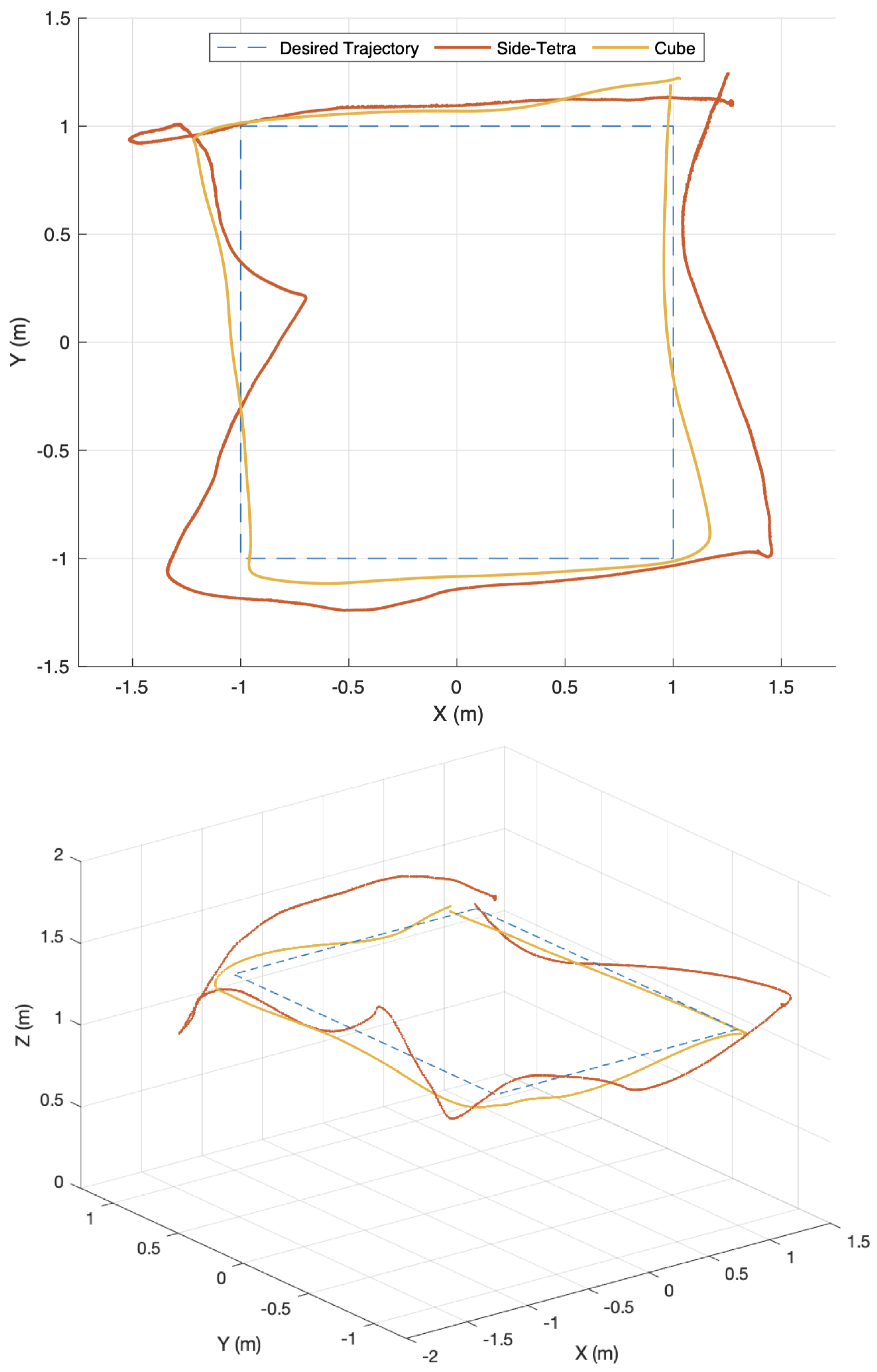
The SpICED prototypes were tasked to follow a series of changing waypoint targets at 30 s interval, using four waypoints with coordinates of [1.0, 1.0], [−1.0, 1.0], [−1.0, −1.0], [1.0, −1.0]. Throughout the experiment, the desired altitude was set to 1.2 m with the desired heading set to 90 degrees. The SpICED prototypes followed the four waypoints targets for three rounds with a consistent performance, and the experimental result of one of the three rounds is shown in Figure 23, with the top plot showing a 2D trajectory of the flights conducted on the plane, and the bottom plot showing the trajectory in 3D. Figure 24 shows the flight data with respect to time, including altitude and yaw with setpoints, which remained constant throughout this experiment. A video of this experiment can be found at: https://youtu.be/PGb66QrO0ik (accessed on 28 July 2022).
Table 4 is the computed Root Mean Square (RMS) error of the trajectory of the two prototypes in each axis from the waypoint experiment. As can be seen, the SpICED (Cube) prototype has significantly fewer errors when compared to the SpICED (Side-tetra.) prototype. Based on this waypoint experiment, a reduction of around 30–40% in RMS error of position control can be seen when comparing the SpICED (Cube) prototype to the SpICED (Side-tetra.) prototype.
From the results of this experiment, it can be seen that the SpICED (Cube) prototype can track the direct paths between the waypoints more closely than the SpICED (Side-tetra.) prototype with fewer deviations. Additionally, the large deviations in altitude and yaw during the X-axis movement of the SpICED (Side-tetra.) prototype shows that there are coupling issues on the side-tetrahedron configuration between horizontal movement and vertical movement and rotation, due to the placement of the PUs, as shown in Figure 3e, where the single PU activated for horizontal thrust also produces vertical thrust and torque components. The sharp correction in the X-axis position of the Side-tetrahedron prototype between the 50 and 55 s mark of the experiment is possibly due to the switching of rotation direction of the PUs, which takes at around 3.5 s, as discovered in our previous paper [20]. In this scenario, as the PUs slow down to reverse the rotation direction, the blimp prototype temporary loses flight control and thus deviates from its intended path, which it then aggressively recovers from when the rotation directions of the PUs are reversed.
In conclusion, the SpICED (Cube) prototype can follow the waypoints and maintain its altitude and yaw control significantly better, with fewer deviations, when compared to the SpICED (Side-tetra.) prototype. This is to be expected, as the SpICED (Cube) configuration uses twice as many PUs, which only rotate in a single direction, so there are no issues with the lag time associated with rotation reversal as compared to the bi-directional PU on the SpICED (Side-tetra.) prototype. The SpICED (Cube) configuration also does not have any coupling issues between the control of different axes due to the placement of counter-rotating PU pairs, which can cancel out any unintended thrust and torque.
5. Conclusions
In the previous paper, the side-tetrahedron configuration chosen for prototyping showed coupling issues when attempting horizontal translation, producing unintended forces and torques along the vertical axis of the blimp. Together with the high lag time caused by the rotation reversal of PU, large deviations were found in the altitude and heading whenever the blimp was tasked to translate horizontally. As the lag time was not modeled in the simulation, the difference in the waypoint tracking result shows its significant influence on control performance.
For the cube configuration tested in this paper, the use of more PUs enabled the PU to be uni-directional and eliminated the need for rotation reversal, which significantly improved the flight control performance of the blimp prototype. However, the use of more PUs caused the weight of the propulsion system to almost double, taking up 45.6% of the total weight budget, with less weight budget left for the battery and electronics system.
In this paper, a proof-of-concept for a safe spherical blimp design with PUs, which provide thrust through the Coandă effect, is presented. Different PU configurations were presented and simulated with the developed control scheme. Experiments were performed on the PU prototypes to determine their performance. Two prototype systems of SpICED with side-tetrahedron and cube configurations were developed and were used to conduct flight control experiments. Lastly, the experimental results show that the SpICED prototype system is controllable, and the differences were discussed.
Future Work
Moving forward, it may be beneficial to explore a feed-forward PID controller design for the side-tetrahedron configuration to reduce the deviations in altitude and yaw whenever horizontal movement is necessary. A smaller, brushless motor in the PU, with a higher torque to drive the impellers, may also improve the control performance, as the current off-the-shelf motor was designed for driving lightweight propellers. Optimizations of the PU’s impeller design may provide more thrust and efficiency, which may also improve SpICED’s control performance.
With the controllabiltiy of the SpICED platform being verified, other aspects of a blimp sUAS could be explored to make further progress in real-world commercial usage scenarios. Some potential research areas may involve the use of a lower-cost indoor localization system such as triangulation using an ultra-wideband radio system, as this may lower the deployment cost of an indoor blimp sUAS and increase adoption. To reduce the operating personnel of the blimp sUAS, it is also necessary to investigate technologies that can be utilised to automate processes such as battery-charging, and refilling helium gas due to losses through the permeability of the blimp’s envelope. The development of a docking station for the blimp sUAS may allow for persistent operations in the indoor environment through automated recharging and refilling processes, and may increase the appeal of this indoor sUAS platform. The processing of information such as images using machine learning techniques may also allow for advanced features, such as the tracking of ground personnel, or enable novel drone–human interaction models.
Author Contributions
Conceptualization, Y.H.P. and S.K.H.W.; methodology, Y.H.P. and S.K.H.W.; software, Y.H.P. and S.K.H.W.; validation, Y.H.P., S.K.H.W. and S.F.; formal analysis, Y.H.P. and S.K.H.W.; investigation, Y.H.P.; resources, S.F.; data curation, Y.H.P.; writing—original draft preparation, Y.H.P.; writing—review and editing, Y.H.P. and S.K.H.W.; visualization, Y.H.P.; supervision, S.F.; project administration, S.F.; funding acquisition, S.F. All authors have read and agreed to the published version of the manuscript.
Funding
This research received no external funding.
Data Availability Statement
Data available upon request.
Conflicts of Interest
The authors declare no conflict of interest.
References
- Drones, A. Drone Noise Levels. 2020. Available online: https://www.airbornedrones.co/drone-noise-levels/ (accessed on 21 July 2021).
- DJI. Phantom 4 Pro. Available online: https://www.dji.com/sg/phantom-4-pro (accessed on 26 July 2021).
- Johnson, J.A.; Svach, M.R.; Brown, L.H. Drone and Other Hobbyist Aircraft Injuries Seen in U.S. Emergency Departments, 2010–2017. Am. J. Prev. Med. 2019, 57, 826–829. [Google Scholar] [CrossRef]
- Burri, M.; Gasser, L.; Käch, M.; Krebs, M.; Laube, S.; Ledergerber, A.; Meier, D.; Michaud, R.; Mosimann, L.; Müri, L.; et al. Design and control of a spherical omnidirectional blimp. In Proceedings of the 2013 IEEE/RSJ International Conference on Intelligent Robots and Systems, Tokyo, Japan, 3–7 November 2013; pp. 1873–1879. [Google Scholar]
- Juang, M. That’s no Balloon, It’s a Drone! Halo Takes to the Skies as Latest Trend in UAVs. 2017. Available online: https://www.cnbc.com/2017/05/06/thats-no-balloon-its-a-drone-halo-takes-to-the-skies-as-latest-trend-in-uavs.html (accessed on 5 July 2021).
- Sharf, I.; Persson, S.; St-Onge, D.; Reeves, N. Development of Aerobots for Satellite Emulation, Architecture and Art; Springer: Berlin/Heidelberg, Germany, 2013. [Google Scholar] [CrossRef]
- Panasonic. Panasonic Develops Ballooncam™ Prototype, A Drone System for Staging Sports And Events. 2016. Available online: https://news.panasonic.com/global/topics/2016/45314.html (accessed on 6 July 2021).
- Festo. eMotionSpheres. 2014. Available online: https://www.festo.com/group/en/cms/10220.htm (accessed on 5 July 2021).
- Festo. FreeMotionHandling. 2017. Available online: https://www.festo.com/group/en/cms/11957.htm (accessed on 5 July 2021).
- Festo. AirPenguins. 2009. Available online: https://www.festo.com/group/en/cms/10242.htm (accessed on 5 July 2021).
- Festo. Air_ray. 2010. Available online: https://www.festo.com/group/en/cms/10245.htm (accessed on 5 July 2021).
- Festo. AirJelly. 2010. Available online: https://www.festo.com/group/en/cms/10244.htm (accessed on 5 July 2021).
- Poon, H.S.; Lam, M.K.; Chow, M.; Li, W.J. Noiseless and vibration-free ionic propulsion technology for indoor surveillance blimps. In Proceedings of the 2009 IEEE International Conference on Robotics and Automation, Kobe, Japan, 12–17 May 2009; pp. 2891–2896. [Google Scholar]
- Yamada, W.; Manabe, H.; Ikeda, D. Zerone: Safety drone with blade-free propulsion. In Proceedings of the 2019 CHI Conference on Human Factors in Computing Systems, Scotland, UK, 4–5 May 2019; pp. 1–8. [Google Scholar]
- Song, S.H.; Shon, H.; Yeon, G.; Choi, H. Design and Implementation of Cloud-Like Soft Drone S-Cloud. In Proceedings of the 2018 IEEE/RSJ International Conference on Intelligent Robots and Systems (IROS), Madrid, Spain, 1–5 October 2018; pp. 1–9. [Google Scholar] [CrossRef]
- Magister, T. The small unmanned aircraft blunt criterion based injury potential estimation. Saf. Sci. 2010, 48, 1313–1320. [Google Scholar] [CrossRef]
- Bir, C.; Viano, D. Design and Injury Assessment Criteria for Blunt Ballistic Impacts. J. Trauma 2005, 57, 1218–1224. [Google Scholar] [CrossRef] [PubMed]
- Sturdivan, L. Modeling in blunt trauma research. In Proceedings of the 2nd Annual Soft Body Armor Symposium, Miami Beach, FL, USA, 1 September 1976. [Google Scholar]
- Clare, V.R.; Lewis, J.H.; Mickiewicz, A.P.; Sturdivan, L.M. Blunt Trauma Data Correlation; Technical Report; Edgewood Arsenal Aberdeen Proving Ground: Edgewood, MD, USA, 1975. [Google Scholar]
- Pheh, Y.H.; Win, S.K.H.; Foong, S. SpICED: Design and Control of a Safe Spherical Blimp using Coandă Effect. In Proceedings of the 2021 IEEE/ASME International Conference on Advanced Intelligent Mechatronics (AIM), Delft, The Netherlands, 13–16 July 2021. [Google Scholar]
- Ahmed, R.; Talib, A.A.; Rafie, A.M.; Djojodihardjo, H. Aerodynamics and flight mechanics of MAV based on Coandă effect. Aerosp. Sci. Technol. 2017, 62, 136–147. [Google Scholar] [CrossRef]
- Eraslan, Y.; Özen, E.; Oktay, T. The Effect of Change in Angle Between Rotor Arms on Trajectory Tracking Quality of a PID Controlled Quadcopter. In Proceedings of the EJONS 10th International Conference on Mathematics, Engineering, NaturalMedical Sciences, Batumi, GA, USA, 15–17 May 2020. [Google Scholar]
- DJI. Mavic Mini. Available online: https://www.dji.com/sg/mavic-mini (accessed on 21 July 2021).
- HP. HP Multi Jet Fusion Technology. Available online: https://www.hp.com/us-en/printers/3d-printers/products/multi-jet-technology.html (accessed on 21 June 2021).
- HobbyKing. Turnigy Nano-Tech 550mAh 2S 65C Lipo Pack (E-Flite Compatible). 2022. Available online: https://hobbyking.com/en_us/turnigy-nano-tech-450mah-2s-65c-lipo-e-flite-compatible-blade-130x-eflb3002s35.html (accessed on 31 August 2022).
- Diatone. MAMBA F40 BLS MINI Dshot600 4IN1 ESC 40A 6S. 2022. Available online: https://www.diatone.us/products/mamba-f40-_bls-mini-dshot600-4in1-esc-40a-6s. (accessed on 31 August 2022).
Figure 1.
Side view showing physical interaction between the impeller and the surrounding air.

Figure 2.
Isometric view of impellers on the PU, (a) Impeller with straight vanes, (b) Impeller with curved vanes.
Figure 2.
Isometric view of impellers on the PU, (a) Impeller with straight vanes, (b) Impeller with curved vanes.

Figure 3.
Types of configuration considered. n = number of PUs. (a) Cube, (b) Prism, (c) Pyramid, (d) Tetrahedron, (e) Side-Tetrahedron. Refer to Table 1 for coordinates of the PUs.
Figure 3.
Types of configuration considered. n = number of PUs. (a) Cube, (b) Prism, (c) Pyramid, (d) Tetrahedron, (e) Side-Tetrahedron. Refer to Table 1 for coordinates of the PUs.

Figure 4.
Free body diagram of SpICED (Cube) with curved-vane impeller PUs.

Figure 5.
Control diagram of SpICED (Cube).

Figure 6.
Control mapping of the PU thrust and torque to the SpICED (Cube) body’s motion in X, Y and Z axes position.
Figure 6.
Control mapping of the PU thrust and torque to the SpICED (Cube) body’s motion in X, Y and Z axes position.

Figure 7.
Control mapping of the PU thrust and torque to the SpICED (Cube) body’s motion in Pitch (), Roll () and Yaw () angle.
Figure 7.
Control mapping of the PU thrust and torque to the SpICED (Cube) body’s motion in Pitch (), Roll () and Yaw () angle.

Figure 8.
(a) Propulsion Unit prototype, (b) Base of Propulsion Unit (motor mount) with brushless motor, (c) Curved vane impeller, (d) Straight vane impeller.
Figure 8.
(a) Propulsion Unit prototype, (b) Base of Propulsion Unit (motor mount) with brushless motor, (c) Curved vane impeller, (d) Straight vane impeller.

Figure 9.
Photo of SpICED (Cube) prototype.

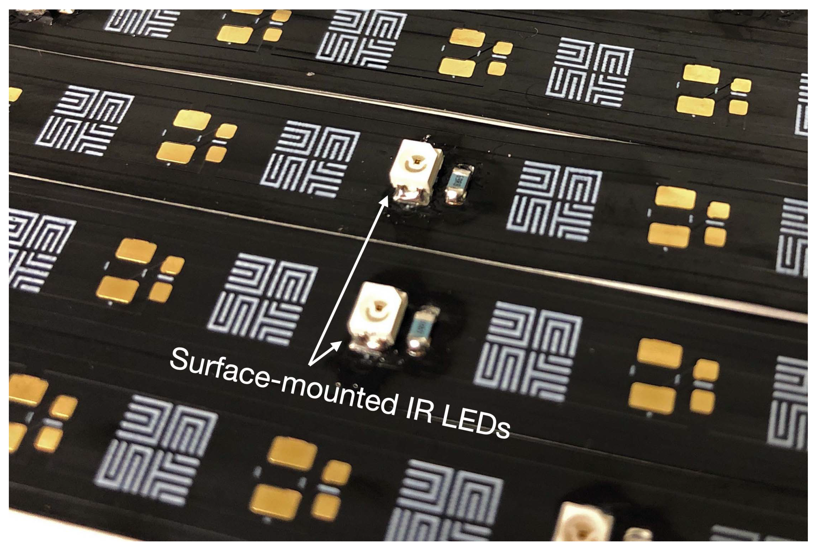
Figure 10.
Surface-mounted IR LEDs on FPC cables connecting the PUs to the ESC.

Figure 11.
Custom designed flight control PCB.

Figure 12.
Electronics and power system on SpICED prototype.

Figure 13.
Mass distribution of the cube prototype and the side-tetrahedron prototype.

Figure 14.
Thrust and torque measurement rig for the Propulsion Unit.

Figure 15.
Electronics interface from Motion Capture System to SpICED prototype.

Figure 16.
and of uni-directional PU with curved impeller spinning in both rotation directions against .
Figure 16.
and of uni-directional PU with curved impeller spinning in both rotation directions against .

Figure 17.
Comparison of and of two types of PU against percentage of actuator signal.

Figure 18.
Comparison of Power and Efficiency of two types of PU against percentage of actuator signal.
Figure 18.
Comparison of Power and Efficiency of two types of PU against percentage of actuator signal.

Figure 19.
Altitude step response of SpICED (Cube).

Figure 20.
Yaw step response of SpICED (Cube).

Figure 21.
Roll step response of SpICED (Cube).

Figure 22.
Pitch step response of SpICED (Cube).

Figure 23.
Trajectory plot of SpICED prototypes in waypoint experiment.

Figure 24.
Time plot of SpICED prototypes in waypoint experiment.


Table 1.
Position of PUs for each configuration.
| Cube | Prism | Pyramid | Tetrahedron | Side-Tetra. | |
|---|---|---|---|---|---|
| P1 | |||||
| P2 | |||||
| P3 | |||||
| P4 | |||||
| P5 | - | - | |||
| P6 | - | - | - | ||
| P7 | - | - | - | - | |
| P8 | - | - | - | - |
Spherical coordinate (r, θ, ϕ) with radial distance r (distance to origin), polar angle θ (angle of rotation from the XY-plane), and azimuthal angle ϕ (angle of rotation from the ZY-plane).
Table 2.
Table of gain parameters (Cube).
| X & Y PID Gains | , , |
| Z PID Gains | , , |
| Pitch & Roll PID Gains | , , |
| Yaw PID Gains | , , |
| Mixing Gains | , |
Table 3.
Specifications of SpICED (Cube) prototype.
| Part | Description | Mass | Num. | Subtotal | % Total |
|---|---|---|---|---|---|
| Envelope | 80 cm diameter foil balloon | 53 g | 1 | 53.0 g | 17.8 |
| Propulsion Unit | Impeller + Motor + Mount | 17 g | 8 | 136.0 g | 45.6 |
| Battery | 2 cell Lithium Polymer [25] | 26 g | 2 | 52.0 g | 17.4 |
| ESC | MAMBA F40 MINI 40A [26] | 8 g | 2 | 16.0 g | 5.4 |
| Flight Control | Custom designed PCB | 7.5 g | 2 | 15.0 g | 5.0 |
| Wires | FPC motor wires | 2 g | 8 | 16.0 g | 5.4 |
| Misc | 3D printed parts | 5 g | 2 | 10.0 g | 3.4 |
| Total | - | - | - | 298.0 g | - |
Table 4.
RMS error of prototypes in waypoint experiment.
| Prototype | X (m) | Y (m) | Z (m) | (°) |
|---|---|---|---|---|
| Side-Tetra configuration | 1.0956 | 0.9669 | 0.1255 | 18.3645 |
| Cube configuration | 0.7626 | 0.6836 | 0.0724 | 11.1234 |
| Reduction in error | 30.39% | 29.3% | 42.31% | 39.43% |
Publisher’s Note: MDPI stays neutral with regard to jurisdictional claims in published maps and institutional affiliations. |
© 2022 by the authors. Licensee MDPI, Basel, Switzerland. This article is an open access article distributed under the terms and conditions of the Creative Commons Attribution (CC BY) license (https://creativecommons.org/licenses/by/4.0/).
Share and Cite
MDPI and ACS Style
Pheh, Y.H.; Kyi Hla Win, S.; Foong, S. Spherical Indoor Coandă Effect Drone (SpICED): A Spherical Blimp sUAS for Safe Indoor Use. Drones 2022, 6, 260. https://doi.org/10.3390/drones6090260
AMA Style
Pheh YH, Kyi Hla Win S, Foong S. Spherical Indoor Coandă Effect Drone (SpICED): A Spherical Blimp sUAS for Safe Indoor Use. Drones. 2022; 6(9):260. https://doi.org/10.3390/drones6090260
Chicago/Turabian StylePheh, Ying Hong, Shane Kyi Hla Win, and Shaohui Foong. 2022. "Spherical Indoor Coandă Effect Drone (SpICED): A Spherical Blimp sUAS for Safe Indoor Use" Drones 6, no. 9: 260. https://doi.org/10.3390/drones6090260