
A Preliminary Study on the Development of a New UAV Concept and the Associated Flight Method
by
 , and
, and
Tiberius-Florian Frigioescu
, 
Mihaela Raluca Condruz
*,
Teodor Adrian Badea
and
Alexandru Paraschiv
National Research and Development Institute for Gas Turbines COMOTI, 220D Iuliu Maniu Av., 061126 Bucharest, Romania
*
Author to whom correspondence should be addressed.
Drones 2023, 7(3), 166; https://doi.org/10.3390/drones7030166
Submission received: 2 February 2023
/
Revised: 22 February 2023
/
Accepted: 25 February 2023
/
Published: 27 February 2023
(This article belongs to the Section Drone Design and Development)
Abstract
:This article presents a preliminary study on the development of a new concept for an unmanned aerial vehicle (UAV) design that incorporates the use of four wings and attached systems to improve overall performance, it being classified as a hybrid quadcopter (a quad tilt wing, tiltrotor UAV). By simulation, it was determined that the developed concept has significant advantages compared with a conventional quadcopter. By implementing this concept, an increase in the maximum speed by 59.21% can be obtained; it reduces time to complete a 10 km route by 36.4%, decreases the energy consumption by 37%, and increases the maximum travel distance by 56.9% at 30% remaining battery capacity. Additionally, the concept improves maneuverability by allowing turning movements to be performed by changing the angle of incidence of the rear wings, resulting in less energy consumption compared to traditional turning methods applied in the case of a conventional quadcopter.
1. Introduction
1.1. Definition and History of UAVs
In the latest decades, an increased interest was registered for the UAV sector, and much research was conducted to develop several UAV types and UAV control systems.
Different institutions use several terms to describe the UAVs; the literature presented them as unmanned aerial systems (UAS), remotely piloted vehicles (RPVs), and drones, but different from precision-guided munition. For example, the International Civil Aviation Organization (ICAO) defined the unmanned aircraft as “an aircraft which is intended to operate with no pilot on board” and the unmanned aircraft system as “an aircraft and its associated elements which are operated with no pilot on board”. Moreover, they refer to the remotely piloted aircraft as a subcategory of unmanned aircraft [1].
The Federal Aviation Administration (FAA) from the U.S. Department of Transportation define the unmanned aircraft as “a device used or intended to be used for flight in the air that has no onboard pilot. This includes all classes of airplanes, helicopters, airships, and translational lift aircraft that have no onboard pilot. Unmanned aircraft are understood to include only those aircraft controllable in three axes and therefore, exclude traditional balloons” [2].
The European Aviation Safety Agency (EASA) define the UAS as “an individual system elements consisting of an “unmanned aircraft”, the “control station” and any other system elements necessary to enable flight, i.e., “command and control link” and “launch and recovery elements”. There may be multiple control stations, command and control links and launch and recovery elements within a UAS” [3].
The precursors of flight and unmanned aircraft date to the ancient world, but the first modern unmanned aircraft was demonstrated in 1916 by inventors Hewitt and Sperry, who designed and manufactured the “Hewitt-Sperry Automatic Airplane” [4].
Since then, many types of unmanned aircraft have been developed and classified by several criteria, e.g., mean takeoff weight (MTOW), size, capabilities, operating conditions, etc. [5].
1.2. Classification of the UAVs
UAVs are used for military and civilian applications, and based on their mission type, they can be reconnaissance and surveillance UAVs. The reconnaissance missions imply acquiring information through visual or other means about what exists or is occurring at a specific location or within a specific region, while surveillance missions imply gathering information about aerospace, surface or subsurface locations, people, or objects using visual, auditory, electronic, photographic, or other methods through systematic observation [6].
Considering their structure and stability, two types of UAVs should be mentioned: fixed- and rotor-wing aircraft. The fixed-wing UAV’s design is similar to that of a conventional airplane. Fixed-wing UAVs can cover large distances and stay aloft for extended periods due to their efficient aerodynamics and fuel-efficient engines. However, they are also more complex to control than rotary-wing UAVs due to the need for takeoff and landing strips, and their limited maneuverability. Rotary-wing UAVs are capable of vertical takeoff and landing (VTOL). Unlike fixed-wing UAVs, which need a runway for takeoff and landing, rotary wing UAVs can take off, hover, and land in small, confined areas. They are powered by one or more rotors that provide lift and propulsion, and their unique design allows for greater maneuverability and stability in the air and are adequate for uneven and inhomogeneous grounds [7,8].
Many UAVs have been successfully applied for monitoring missions to improve or supplement conventional field observations [9,10]. For example, they were deployed for surveillance in protected areas [11], land fields [12,13], and forests [14]. They are a safe method to study fierce wild animals (e.g., the Nile crocodile [15]), as an anti-poaching tool [16,17], and in the aquaculture field [18].
It was reported that UAVs were also used for the infrared imaging of photovoltaic systems [19] in the wind energy field, where they were deployed to retrieve information about wind flow, turbulence intensity, vertical wind components, and shear at the escarpment site [20]. Other fields that benefit from the advantages of UAVs are the archaeological and agricultural fields and cartography, where RPAs were used for surveillance and aerial photography [21,22,23,24,25]. Except for these applications, they were deployed for structural safety inspections, such as buildings and bridges with high seismic risk [26].
1.3. Aim of the Present Work
The European demand for UAVs is increasing, especially for civil missions, and is anticipated to represent more than EUR 5 billion of the annual value of 10 billion annually by 2035 [27]. This demand increase justifies the need to design and develop new types of UAVs. Moreover, this trend to develop new UAVs or different methods to improve their functionality was registered [28,29]. Currently, multi-rotors are preferred for the operation due to their maneuverability, hovering capability, and slow speed turns compared to fixed-wing UAVs that cannot fly below their speed limit. However, their drawback is that multi-rotors have much shorter flight autonomy compared to fixed-wing counterparts. Therefore, current research aims to find solutions to increase the flight autonomy of multi-rotors. Hence, this article presents a solution for increasing the flight autonomy.
Except for fixed- and rotor-wing aircraft, in the literature, there is available information regarding hybrid UAVs, such as fixed-wing VTOL UAVs [30,31,32,33], but also quad tilt-wing UAVs [34,35,36,37] that benefit from the advantages of both baseline UAVs. Further, several patents were identified that refer to UAVs with wings or tiltrotors [38,39,40]. Even though these UAV models were found in the literature, there was not one identified that integrates both tiltrotors and tilt wings.
This paper presents a preliminary study on the development of a new UAV concept and the associated flight method. This concept aims to increase the flight autonomy and maximize the flight speed of the aircraft by using wings and tiltrotors, compared with a conventional quadcopter. An iterative approach was used for developing this UAV concept. The concept and the associated flight method are based on the latest research in the UAV field and are intended to provide a novel solution in terms of UAV design and operation.
The brief design and validation plan of the UAV concept is presented in Figure 1. This paper describes three stages of the experiment (Design and modeling of the structural components, Design of the electronic configuration, and Performance calculation). The Design and development of a remote-control test bench for the propulsion system and Testing and validation of the propulsion system were published in [41], while a future study will be made that will integrate all the other stages for the development plan, including actual flight test results.
2. Materials and Methods
To design and computationally validate the UAV concept, three software were used: SolidEdge ST9 for CAD design, Matlab R2020a for performance evaluation of the UAV concept, and Ansys CFX R19.2 version for wing flow simulation.
The UAV concept developed consisted of a hybrid quadcopter, a quad tilt wing, and tiltrotor UAV that uses four moving wings mounted on the engines’ support arms. It is a classic X-shaped configuration of a quadcopter, with four arms supporting the motors positioned in an X shape, with a 90° angle between them. The aim of the wings is to generate additional lift force for the advance movement of the UAV. To design the UAV concept, the designing principles for additive manufacturing were applied, as many parts as possible of the UAV experimental model are intended to be manufactured by the CFF process (continuous fiber fabrication), using composite materials based on a polymeric matrix reinforced with continuous carbon fiber, and SLA (stereolithography), but also by conventional methods applied to manufacture polymeric composite structures.
A flow simulation was performed for the aircraft’s wing configuration. For simulation, two different air speeds were used, a 10 m/s and a 20 m/s, and five angles of incidence (0°, 3.53°, 7.05°, 10.55°, and 14°). For this type of wing, the values for drag and lift were extracted from the analysis at the speeds and the angles of incidence previously mentioned. The mechanism for changing the wing’s angle of incidence is composed of a servomotor mounted on the central area of the quadcopter and which, through an arm, changes the angle of the wing. Due to the geometry, the angle of rotation of the servomotor is not the same as the wing’s angle of incidence. The correspondences are the following (left- servomotor rotation angle, right- wing incidence angle): 0°–0°, 5°–3.53°, 10°–7.05°, 15°–10.55°, 20°–14°. Therefore, an adjustment law was made between the rotation of the servomotor and the rotation of the angle of incidence of the wing.
The rotation mechanism of the tilting of the rotors is made up of a servo motor that is mechanically connected directly to the plate on which the motor is placed, the free rotation being ensured by 2 bearings. Here, the rotation angle of the servomotor is equal to the tilt angle of the rotor.
In the numerical simulations, the drag coefficient and the lift coefficient in the 5 angles were evaluated to make an interpolation between them and use the function as input data in the program developed in Matlab to simulate the obtained performance by using the concept.
Commercially available electronical equipment was considered to equip a basic configuration of the UAV concept and to evaluate its performance. A calculation program was developed in Matlab to validate the UAV concept and the associated flight method. Using flight dynamics equations, the performance of the UAV was estimated in three different scenarios: hover flight, a conventional quadcopter flight, and the UAV concept’s flight with increased maximum speed.
In hover flight, the UAV can maintain a stable position in the air without moving forward or backward and without losing altitude. In the conventional quadcopter flight scenario, the effects of the wings and engine vectoring were excluded, and the UAV was considered to have fixed engines and no wings. In the case of the new UAV concept’s flight with increased maximum speed, the wings generated lift force and the engines were vectored according to that force, while the engine speed was kept constant. This increased the maximum flight speed.
The following data were used as inputs for the performance calculation: 1.23 kg/m3 air density, 9.81 m/s2 gravitational acceleration, 16,000 mAh battery capacity, 32,000 mAh total capacity of the UAV, 12.5 kg UAV mass, and the PWM (pulse-width modulation) percentage from 1 to 80%.
All the equations used to describe the flight and performances of the UAV concept and the associated flight method are presented in the Results section. The Results section was presented iteratively, following the diagram from Figure 2.
3. Results
3.1. Design and Definition of the UAV Concept
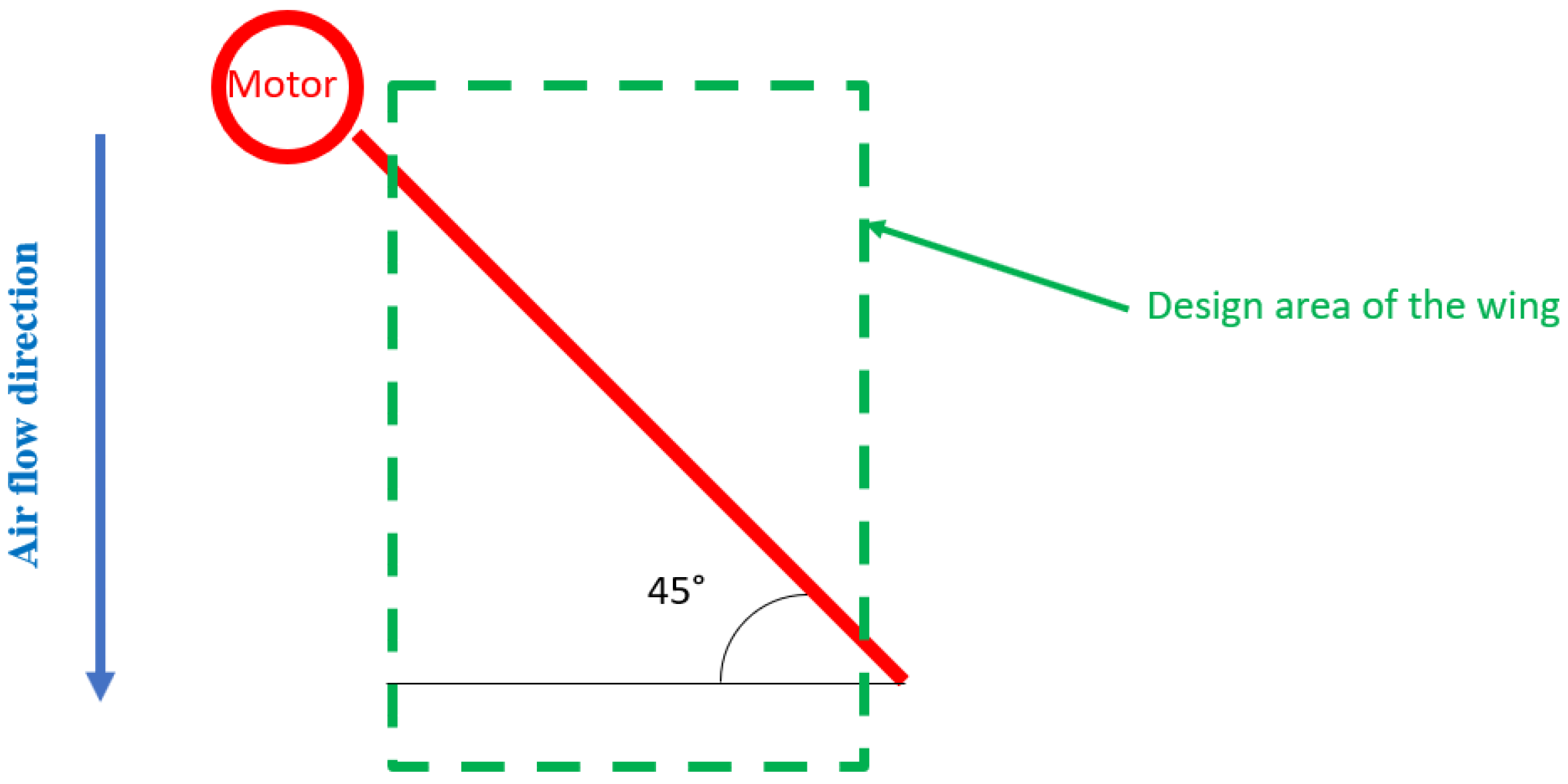
An innovative aspect of this concept model is the addition of a wing mounted on each support arm, as can be seen in the schematic representation from Figure 3.
To address this challenge, a technical solution was proposed. A NACA 5412 profile was selected, but with two different chord dimensions, a 100 mm chord at both wings’ tips and a 300 mm chord in the middle of the wing, resulting in a span of 282.84 mm. The usual pivot arm was replaced with a pivot that allowed the wing to be mounted over the entire span at 25% of the chord from the leading edge. The resulting wing design, as shown in Figure 4, featured ribs and a shape optimized to maximize the lift surface within the limited space between the engine and the UAV central body.
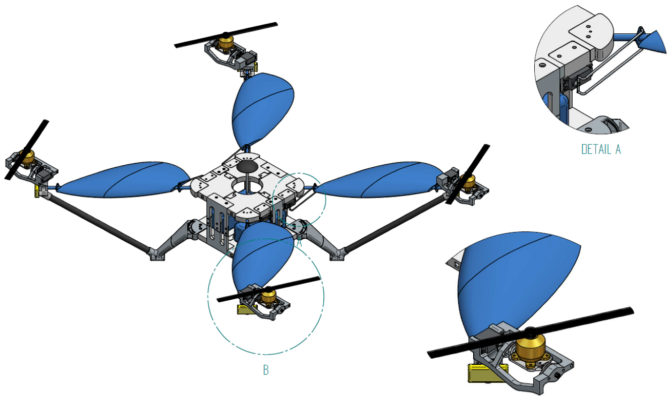
The 2D sketch from Figure 4 presents the front-left (FL) wing, which is identical to the right-rear (RR) wing. Similarly, the right-front (RF) wing is identical to the left-rear (LR) wing. A 3D CAD model with the hybrid quadcopter is shown in the images from Figure 5. Figure 5 shows the UAV conceptual model where the four rotors and designed wings mounted on the rotors’ support arms are displayed. Here, it can be seen that the FL wing and RF wing are mirror parts, while the wings on the diagonal are identical.
The advance of a conventional quadcopter is achieved by decreasing the speed of the two front engines, causing an inclination of the UAV, implicitly an inclination of the lift force (propulsion force), forming a triangle of forces. The propulsion force is broken down into two components, one that has the role of maintaining the UAV at a certain altitude and the other component being parallel to the direction of travel, making it move forward. Acceleration becomes maximum for this force value and gradually decreases with increasing travel speed because the drag also increases. Acceleration becomes 0 when the component force in the advance direction becomes equal to the drag resistance. From this point, to increase the advance speed, the angle of inclination of the aircraft is increased by reducing the speed of the front engines in a transient regime. By mounting the four wings on the arms of the quadcopter, the flight’s principle changes.
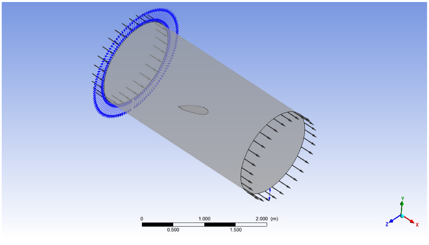
The flow simulation performed for this type of wing was carried out to evaluate the influence of the wing on the quadcopter structure. It was performed by placing the wing within a calculation domain, as exemplified in Figure 6.
The results obtained are presented in Table 1, while for the case of 0° incidence and speed of 20 m/s, the results regarding the speed distribution are also presented in the images from Figure 7.
This lift added by the wings can be subtracted from the vertical component of the propulsion force by changing the angles of the engines and their speed. It must be considered that the horizontal component of the propulsion force must be increased by the amount of total drag added by the wings. At 14° incidence and a speed of 20 m/s, this force has a value of 4.63 N.
Regarding the structure of the hybrid quadcopter, the central area (body of the quadcopter) was designed to be manufactured from carbon-fiber-reinforced polymeric composites, consisting in two plates (upper and bottom plate) linked by four support pillars that will also be manufactured by the additive manufacturing methods. From the level of the upper plate, four rods are made of carbon-fiber-reinforced polymer composites by conventional methods, oriented at an angle of 45° relative to the upper plate. These rods will support and take over the lift generated by the wings; thereby, they will be called quadcopter arms. On these arms will be mounted the wings, whose angle of incidence will be changed during the flight with servomotors mounted on the upper plate. Attached to the bottom plate are four landing legs that were also designed to be made by additive manufacturing.
At the end of the arms of the quadcopter, the motors are attached to the rotation device connected to a servomotor for each motor. To ensure better stability, great rigidity on the arms, and a passage channel for the electric cables, an additional composite rod will be integrated between the leg of the quadcopter and the motor support, which will reinforce the structure, and through which will pass the electrical cables for the motor and servomotor. Propellers are attached to the engines that will generate the thrust required for lift and propulsion.
3.2. Electronic Equipment of the UAV
As it was mentioned, the hybrid quadcopter was designed to integrate many electronical components to function:
- ➢
- 4 engines
- ➢
- 8 servomotors (4 to move the wings and 4 to move the engines)
- ➢
- 4 ESCs (electronic speed controller)
- ➢
- 2 Single-board computers
- ➢
- Accumulator
- ➢
- Voltage reducer
- ➢
- GPS
- ➢
- Accelerometer and gyroscope
- ➢
- Signal transmission system with emission-reception
On the first computer, the ArduPilot software will be installed, which oversees the motors’ control. It ensures stability and controls the UAV as a conventional quadcopter. The second computer controls all eight servomotors (four servomotors for adjusting the wings’ angle of incidence and the other four servomotors for adjusting the tilt angle of the rotors). Within this computer, an internal developed software using Python will be integrated; this software will ensure both manual and automatic adjustment of the angles depending on travel velocity, pitch angle, and altitude. The second computer follows the actions of computer 1 and steps in to change the angles, thereby ensuring the use of the new concept.
In the central area (the body of the quadcopter), the following components will be stored: the battery, the SBC (Single-board computer), the ESCs (Electronic speed controller), the GPS, the gyroscope, the accelerometer, the signal transmission-reception system, and other optional sensors.
Figure 8 shows the basic electrical diagram of the quadcopter with the following notations:
- PWD—Power Drive Hut (power distribution system)
- A&G—accelerometer and gyroscope
- TR—signal transmission system with emission-reception
- FL—front left
- FR—front right
- LR—left rear
- RR—right rear
- SBC—single board computer
The red electrical wires are connected to the positive terminal, the black ones to the negative terminal, and the green wires are for data transmission. Thin wires are of low amperage, and thick ones are of high power, i.e., amperage over 10 A.
The proposed battery will be a 32,000 mAh type 6 S with a discharge capacity between 10 and 20 C, offering a maximum amperage between 320 and 640 A. Considering its cells (6 S), a cell can give approximately 4.2 V. Thus, the battery will generate a voltage of 25.2 V.
The SBC will be powered from the battery, but a voltage reducer up to 5 V will be mounted between them to power it. The SBC will be a Raspberry Pi 4 model B. This SBC will contain the script programmed to control the quadcopter. Thus, this board becomes the monitoring, control, and transmission system of the quadcopter.
Another SBC will control the eight servo-motors, (four for the wings and four for the engines). The ESC controls the engine speed by varying the voltage and thus the amperage. The four ESCs will be controlled by the SBC, but powered directly from the battery.
All the wires from the battery will be connected in parallel to keep the voltage and divide the current. The ESC is powered directly from the battery because it needs high current and will provide this power to the motor. Thus, the motor is only connected to the ESC. The ESC has a low-intensity positive wire that can power other devices (even if this base configuration does not apply).
The SBC will provide control of the quadcopter through these motors and servomotors, but to do so, it needs coordinates. The GPS gives the geographical position in XYZ coordinates, and the accelerometer with the gyroscope will provide data about its inclination and movements. Using these two devices, the quadcopter is monitored. The last device, TR, has the role of receiving and issuing commands and data.
The ESCs must have a maximum current of 70 A, and the motors must be between 700 and 1000 KV and around 1000 W for the UAV to be lifted off the ground.
3.3. Associated Flight Method
The proposed conceptual model of the quadcopter uses structurally mounted wings on the support arms of the four engines to generate additional lift force for the forward movement of the UAV. To achieve takeoff, the speed of the four engines is increased until the propulsive force generated by the propellers exceeds the weight of the UAV. For stabilization, the propulsive force must be equal to the gravity force, assuming that the center of gravity is at the intersection of the diagonals of the motors and there are no environmental disturbances (such as wind). However, in real-world conditions, external forces from the ambient environment, as well as the configuration of the UAV, may shift the center of gravity and affect its stability. The gyroscopic system is used to detect and correct any tilt, thus maintaining the stability of the aircraft using Euler angles and the speed of the four motors.
For landing, the speed of the four engines is decreased until the propulsive force becomes less than the weight force, resulting in a downward movement of the drone. At altitudes higher than 20 m, the altitude is determined using GPS. At altitudes lower than 20 m, the altitude is determined using an ultrasonic sensor to ensure a smooth landing at the ground level.
During forward movement, the UAV maintains a fixed altitude by balancing the propulsive force and weight forces. To achieve this, the speed of the front engines is reduced, causing the drone to bank. The propulsion force is broken down into vertical and horizontal components, and the stall speed begins to increase. The wings are designed to change their angle of incidence from negative to positive, creating a lift on their surface. To maintain the altitude, the sum of the lift force and the vertical component of the propulsive force must equal the weight. This is achieved by directing the engines at a specific angle in relation to the direction of travel, which increases forward speed compared to a classic quadcopter.
When moving forward, according to what was discussed previously, the UAV being at a certain altitude, the following steps will be followed:
- I.
- Lifting the aircraft from the ground by increasing the speed of the four engines, the propulsion force being greater than the weight.
- II.
- Keeping the UAV at a fixed point by equalizing the two forces (propulsive force with weight).
- III.
- Reducing the speed of the front engines, the UAV starts to bank, the propulsion force breaks down into two components (vertical and horizontal), and the stall speed starts to increase.
- IV.
- The wings take their angle of incidence from negative to positive to achieve lift on their surface.
- V.
- Due to the appearance of lift force, the sum of it and the vertical component of the propulsive force component must be equal to the weight, so the speed of the engines should decrease; but this is avoided, and the engines will be directed at a certain angle with the direction of travel so that altitude remains constant, which increases forward speed compared to a classic quadcopter. The graphical representation of these five steps is presented in Figure 9.
The action described in step V of the flight technique, outlined in Figure 9, results in increasing the forward speed of the UAV, which decreases electrical energy consumption and, thus, an increase in flight autonomy. Additionally, during this step, the engines can be run at higher rotation per minute (RPM) than normal, which allows for a higher travel speed than that of a conventional quadcopter, as the propulsion force is focused on the direction of travel rather than on the vertical axis. The angles presented in Figure 9 are not actual calculated values necessary for flight stability, but rather they provide qualitative information regarding the flight technique. The width of the UAV between motor axes 1 and 2 (or 3 and 4) is 1198.9 mm, and the length between motor axes 1 and 3 (or 2 and 4) is 987.7 mm. These values will be necessary for calculating the rotation moments.
The rotation of a propeller causes a reactive moment in the opposite direction of the propeller’s rotation. This effect is the most evident in helicopters. When the main rotor (main propeller) rotates clockwise, due to the reactive moment, the helicopter tends to rotate counterclockwise. This reactive moment is countered by mounting a propeller on the tail of the helicopter, which creates a force that, multiplied by the distance from the propeller to the main rotor axis, creates a moment in the opposite direction and equal in magnitude to the reactive moment. Thus, with four motors, four reactive moments are created. These are countered by changing the rotation direction of two of them. Thus, motors 1 and 4 will have a clockwise rotation direction, while motors 2 and 3 will rotate counterclockwise. Having the same rotation direction on the diagonal of the UAV, its stability is improved, and the reactive moments generated by motor 1 and 4 will be countered by the reactive moments of motors 2 and 3. Due to the presence of the two rotation directions, the UAV has four propellers, which are of two types (two by two identical).
Figure 10 presents an image with the top view of the UAV concept with the direction of rotation of the engines.
The flight physics for a conventional quadcopter are exemplified by using the following notations:
T1—the force generated by motor 1 [N]
T2—the force generated by motor 2 [N]
T3—the force generated by motor 3 [N]
T4—the force generated by motor 4 [N]
G—Weight of the UAV [N]
g—gravitational acceleration [m/s2]
m—UAV mass [Kg]
ψ—Yaw angle [°]
θ—Pitch angle [°]
ϕ—Roll angle [°]
Mψ—Yaw moment [Nm]
Mθ—Pitch moment [Nm]
Mϕ—Roll moment [Nm]
ax—X acceleration [m/s2]
ρ—Air density [Kg/m3]
Cx—Drag coefficient on X
Af—Frontal area of drone [m2]
Vx—Velocity on X [m/s]
Cz—Drag coefficient on Z
Az—XY area of drone [m2]
Vz—Velocity on Z [m/s]
az—Vertical acceleration [m/s2]
Cy—Drag coefficient on Y
Ay—XZ area of UAV [m2]
Vy—Velocity on Y [m/s]
ay—Acceleration on Y [m/s2]
Figure 11 shows the UAV with the forces represented and yaw, pitch, and roll angles. The X-axis shows the UAV’s forward direction, the Y-axis is perpendicular to X, and the Z-axis is perpendicular to the XY plane. The tilt of the UAV about the X-axis forms the roll angle ϕ. The rotation about the Z-axis is represented by the yaw angle ψ, and rotation about the Y-axis forms the pitch angle θ.
To obtain the aerodynamic stability of the UAV, we consider that the quadcopter is at a certain altitude in the hover position (altitude hold and fixed point). Thus, realizing the balance of forces vertically, Equation (1) conditions are fulfilled:
In Equation (1), the pitch and roll angle (θ and ϕ) are equal to 0, so their cosine is equal to 1. The discussed angles have the value 0 only when the drone is in the hover position. To maintain the stability of the UAV at a constant altitude, Equation (1) must be equal to 0; that is, the vertical acceleration must be 0. Further, to keep the UAV at a fixed point, the propulsion force composed of the four forces of the motors must have the direction of the Z-axis. For this to be achievable, the yaw, pitch, and roll moments must be 0. Thus, Equations (2)–(4) show the main moments of the aircraft.
As Equations (2)–(4) are valid for the hover flight, further movement of the aircraft on the three axes must be considered, and Equations (5)–(7) are used.
Having Equations (5)–(7), we can extract the three accelerations on X, Y, and Z. On the X-axis, the forces involved in the acceleration on this axis are the four propulsion forces in accordance with the angles of pitch and roll. These forces are opposed by the drag force, which increases with the speed of travel on X and depends on the airfoil and pitch and roll angles. On the Y-axis, the situation is the same as on the Y-axis, except that the forward resistance is on the side of the quadcopter, and acceleration is given on the X-axis. In the case of the Z-axis, the acceleration is related to the thrust forces, the pitch and roll angles, and the force of vertical resistance, but also the weight force generated by the total mass of the quadcopter.
As the equations presented are for the conventional quadcopter, where the wings and vectorization of the motors are not available, further the Equations (8)–(10) were presented for the specific concept of the hybrid quadcopter with the wings and engine vectoring.
The UAV concept described has independent vectoring on each engine and a variable angle of incidence on each wing. In the case of vectoring motors, the rotation of the related servo-motor axis implies the same rotation of the motor, respectively, the propeller. In the case of controlling the angle of incidence of a wing, the rotation does not correspond to the rotation of the wing. Thus, the angle of incidence is a function of the angle of rotation of the wing about the 8 mm diameter rod that, in turn, is a function of the angle of rotation of the servo motor shaft.
The equations corresponding to these two features are presented:
where:
—The vectorization angles of the propulsion forces T1, T2, T3, and T4 [°]
—The incidence angles of the lift forces corresponding to the wings FL, FR, LR, and RR [°]
Pi—The lifting force given by the wing [N]
—X-axis propulsion force of motor i [N]
—Propulsion force on the Z-axis of the motor i [N]
—Lift coefficient
According to the equations and design, the propulsive force generated by driving a propeller is broken down into two components: one on the X-axis and one on the Z-axis, this depending on the vectoring angle related to the motor. In the case of the wing, its effect becomes present once the displacement speed becomes different from 0. By changing the angle of incidence, the lift coefficient changes, therefore, also the lift provided by the wing when moving it through an air current. Further, Equations (5)–(7) were rewritten by introducing the vectorization factors of the engines and the wing presence (Az_wing being the area of the wing), and Equations (11)–(13) resulted.
Equations (11)–(13) reproduce the forces acting on the UAV using the advantages of motor and wing vectoring in hover, X-axis, and/or side-tilt (ϕ ≠ 0) flight. Figure 12 presents a flight case where: , , , , and .
Moreover, in the presence of wings and vectorization, Equations (2)–(4) became Equations (14)–(16).
where:
where:
where:
—distance on X from center of drone to pressure center of a wing [m]
—distance on Y from center of drone to pressure center of a wing [m]
The equations for the UAV concept deviate from the mathematical model of a conventional quadcopter, introducing new components and significant changes. In particular, the equations for the three accelerations show a greater degree of control over the direction of the propulsive force, with the ability to adjust each propulsive force individually, as well as the addition of four lift force components that can be controlled individually. The system of moments for the three primary axes reveals four lift forces generated by the four wings, which have a direct impact on the maneuverability of the drone. Due to their inclusion and the ability to independently control the angle of incidence for each wing, the drone can perform maneuvers with greater efficiency, requiring less time or energy consumption by selectively adjusting the corresponding lift forces.
3.4. Theoretical Performance Evaluation
A calculation program was developed in Matlab to validate the UAV concept and the associated flight method. Using flight dynamics equations, the performance of the UAV was estimated in three different scenarios: hover flight, a conventional quadcopter flight, and the UAV concept’s flight with increased maximum speed.
The mass of the UAV was imposed, and the lift coefficient of the wings was determined by a previous simulation, and the performance of the engine configuration was analyzed. The results were processed as polynomial equations of the 5th degree according to the PWM percentage.
3.4.1. Hover Flight
The mass of the UAV was 12.5 Kg, which means that the force required for the hover is 122.625 N, and returning on each motor required a force of 30.6563 N. Thus, these data correspond to the following analysis:
- -
- Current intensity per motor during hover is 44.7032 A
- -
- The total current consumed by the UAV during the hover was 178.8129 A
- -
- The power consumed by a motor during hover was 755.3243 W
- -
- The total power consumed by the drone during hover was 3021.3 W
- -
- Engine speed during hover was 11 152 rpm
- -
- PWM percentage during hover was 52.88%
The UAV was equipped with two batteries and thereby returns a power consumption per battery of 1510.6 W and an intensity of 89.4065 A. As a general performance, the autonomy of the UAV during the hover is 10.73 min., and in the case of battery discharge up to 30%, the autonomy is reduced to 7.51 min.
3.4.2. Flight Simulation for Conventional Quadcopter
To simulate the flight as a conventional quadcopter, the same mass and configuration of the UAV were used, only this time the motors were fixed, and the presence of wings was not considered. Thus, it was considered that the UAV is at a certain altitude, the travel speed is 0, and the flight is at a fixed point. Starting the route involves tilting the UAV around the Y-axis with a pitch angle of 20°. The transient process is not taken in the simulation calculation.
The system has two equations and two unknowns, namely, the total propulsive force generated by the engines and the displacement acceleration. The vertical acceleration was 0. Therefore, the system was solved iteratively, with an initial travel speed equal to 0, at which the value is changed by the following formulas:
where:
t—Time step [s]
i—Number of iterations
Dist—Traveled distance [m]
The time step was equal to 0.1 s, meaning that after every 0.1 s, the system (11) was calculated and with Equation (12), after which it returned with the new travel speed in the system. This was done until the distance reached a value of 10 km. At this point, the route simulation was finished.
The route simulation analysis provided the following results (Route simulation in conventional quadcopter mode as Figure 13):
- -
- Motor PWM percentage: 54.66%
- -
- Travel time of the route: 6093 min
- -
- Maximum travel speed: 99.99 km/h
- -
- Power of a motor: 803.40 W
- -
- Total motor power: 3213.6 W
- -
- Energy consumption following the route: 19198 mAh
- -
- Percentage consumed from the battery is: 59.99%
3.4.3. UAV Concept’s Flight with Increased Maximum Speed
This case presents route flight using the advantages of the concept (hybrid quadcopter). Having two flight modes, this simulation will use the algorithm that will keep the engine speed constant, with the entry of wings and vectoring of the engines resulting in the increase of the maximum flight speed. The system of equations for this simulation is as follows:
The system above consists of two equations and two unknowns represented by the displacement acceleration and vectoring angle. The required motor RPM was taken from the classic quadcopter case, which is the same (constant RPM mode). Further, it is assumed that the wings are at an angle of incidence of 10.8° in the initial state, with a lift coefficient of 1.112443.
The system is solved iteratively, with a time step of 0.1 s after each resolution, calculating the distance and new displacement speed according to Equation (12). Moreover, as the displacement speed increases, the lift of the wings increases, and the vectoring angle also increases. The theoretical limits for this would be when the vectoring angle added to the pitch angle makes 90°. In practice, due to the UAV’s configuration, on engines 3 and 4, the vectoring angle can reach a maximum of 45°, because from here, the propeller hits the wing. Thus, in the establishment of the code in Matlab, it was imposed that the vectoring angle should not exceed 45°. Further, to do this, when the vectoring angle exceeds 40°, the angle of incidence of the wings is lowered to decrease the lift provided by them and thus limit the vectoring angle.
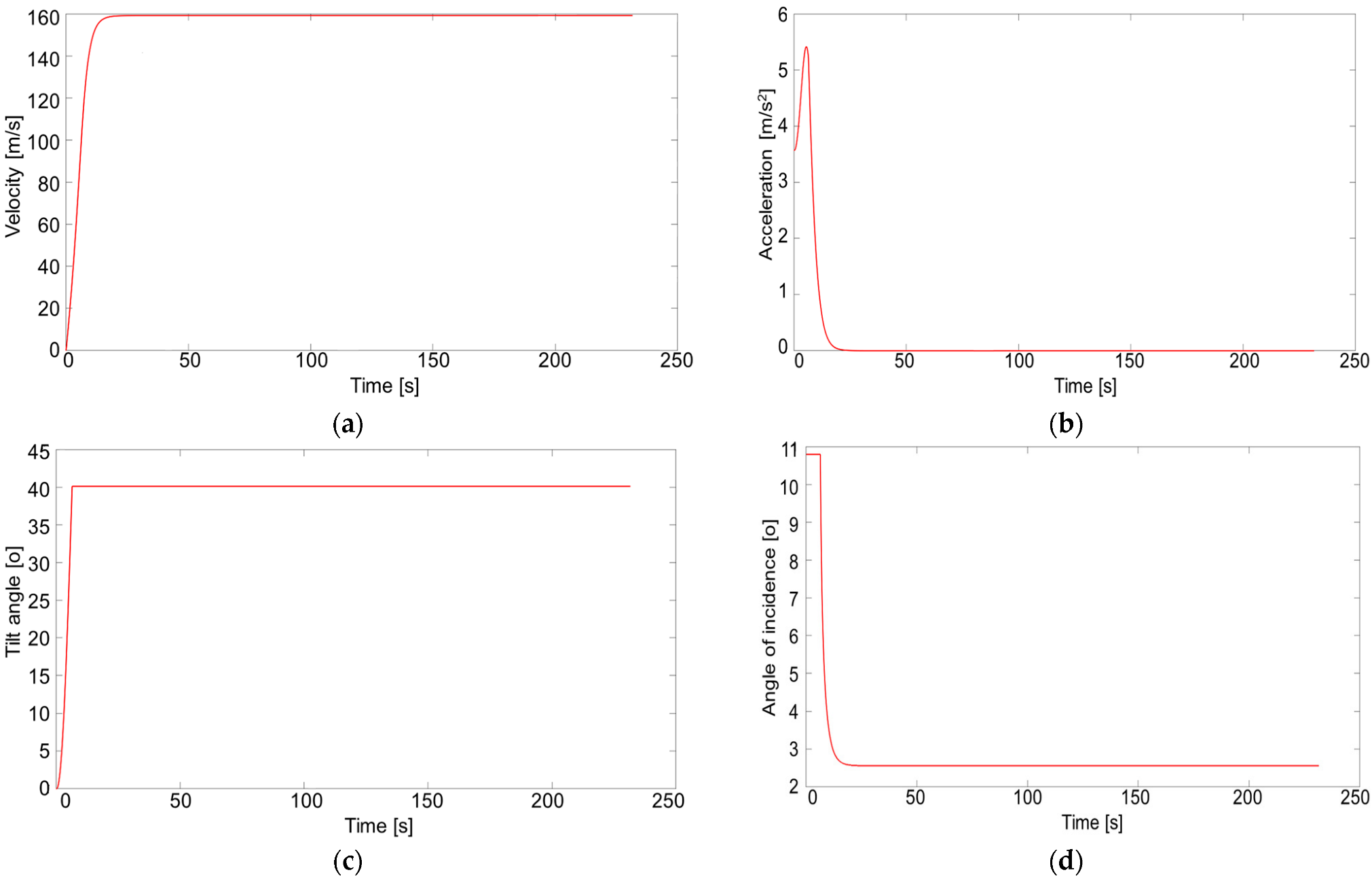
Therefore, the route simulation was done and the following results were exported (Route simulation in hybrid mode with increased maximum flight speed as Figure 14):
- -
- Time to complete the route: 3.86 min
- -
- Maximum speed reached: 159.21 km/h
- -
- Power per motor: 803.40 W
- -
- Total power consumed by the engine: 3213.6 W
- -
- Energy consumption to complete the route: 12162 mAh
- -
- Percentage consumed from the battery: 38%
The maximum speed is reached after approximately 25 s, with an initial acceleration of 3.5 m/s2. As the speed increases, so does the vectoring angle, leading to an acceleration of up to 5.5 m/s2. However, once the vectoring angle reaches 40°, the lift of the wings starts to decrease due to the decrease in the angle of incidence. The vectoring angle remains at 40° throughout the flight. Initially, the angle of incidence is kept at 10.8° until the vectoring angle reaches 40°. From this point, to maintain the vectoring angle at 40°, the angle of incidence begins to decrease until the displacement acceleration becomes 0. At this point, the angle of incidence remains constant at 2.56°.
4. Discussion
The UAV concept developed represents the optimization of a conventional quadcopter in terms of flight autonomy and maximum flight speed using tilt wings and tilt rotors. An innovative aspect of this concept is the addition of a wing mounted on each support arm. These wings were not designed as conventional fixed wings due to their placement. Moreover, they are not as big as other quad tilt wings, and they have a more elegant design. On a conventional fixed-wing aircraft, the airfoil is parallel to the direction of the airflow, while in this case, as it is a hybrid quadcopter, the wing is positioned at a 45° angle to the direction of the airflow. In the case of other quad tilt-wing UAVs, the wing is positioned perpendicular to the wind direction [34], while in this configuration, the wing has its airfoil parallel to the direction of the airflow, and its design was optimized for a large lift surface. Moreover, Cetinsoy et al. [34] used motors attached to the wings, and the tilt is made by only four servomotors. This innovative concept can withstand a higher wind level during the flight to a fixed point compared to their UAV, because in their case, for flight to a fixed point, the wings are in a vertical position. Further, another major advantage of the present UAV is the fact that there are eight independent control points, four on the tilt wings and four on the tilt rotors, which leads to a much better optimization for turns and flight mechanics.
In the patent of Lavagen et al. [38], they present a hybrid UAV consisting in a central fuselage, four arms with four propeller-powered motors, and four butterfly-style wings. One disadvantage of this device is that its vertical take-off is susceptible to wind influence; the motor vectorization is limited; and for forward flight, the device must rotate about 90° toward the direction of movement. Another UAV, known as a quadcopter, is described in [39], consisting of a central fuselage with four arms attached, with four propeller-powered motors maintaining a horizontal fuselage throughout flight. The disadvantage of this device is that the aircraft’s lift is entirely generated by the four propellers, with a maximum motor vectorization angle of −60° to +60° relative to the vertical, and vectorization is not independent for each motor, but both front and rear motors are linked to each other in pairs by a shaft.
Other UAV, described in [40], consisted of a central fuselage with four arms equipped with flapping wings driven by a central motor. The disadvantage of this device is that its design is suitable for small aircraft, cannot carry a large load, has a complex and difficult-to-achieve flight stability, and the arm wings require special fatigue-resistant materials due to flapping movement. The main disadvantage of these three UAVs is that the lift is entirely generated by the four electric motors, leading to high energy consumption and reducing flight autonomy. Additionally, the maximum speed is limited by the angle of decomposition of the total motor force through their means of propulsion. This concept solves the problems encountered in the case of the previous mentioned inventions—it improves the lift force, directing the motors’ force for advancement through the vectorized propulsion mechanism, thereby increasing the autonomy and maximum flight speed of the UAV.
Based on all research made, the developed concept brings significant overall performance advantages, including increased maximum speed, decreased time to complete a route, decreased energy consumption, and increased maximum travel distance up to 30% remaining battery capacity. However, these advantages come at the expense of an increase in mass due to the presence of the four wings and the systems attached to their use. A simulation was conducted in Matlab to evaluate these performance advantages, and a Cx was considered in the simulation, so that the maximum speed was set at 100 km/h. However, it should be noted that the Cx could not be evaluated through numerical simulation and will need to be evaluated experimentally in future research. Additionally, it should be noted that the advantages of using the wing are present only in movements when there is a certain speed for the wings to generate lift. In flight to a fixed point, this innovation is just an extra weight.
The advantages brought by the innovation are given both in flight autonomy and in maneuverability; but for maneuverability, a complex flight control program must be created to work in sync with the servomotors to change the angle of incidence.
Another advantage introduced by this concept is that the turning movement can be performed by changing the angle of incidence of a rear wing. This means that turns can be performed with insignificant energy consumption in relation to the consumption of the motors by changing the speed of the motors diagonally, as opposed to performing a turn movement in the traditional way.
The following advantages of the UAV concept can be highlighted:
- Vertical takeoff/landing.
- Allows the transport of a high-capacity payload.
- It has vectorized propulsion.
- It has increased flight autonomy due to the generation of a lift force by the wings and the reduction of rotation per minute at the four motors.
- Increased maximum forward speed due to flight principle, as the motor thrust can be fully focused on the forward direction.
- Increased maneuverability because each wing is independently adjustable regarding incidence angle.
Future research includes manufacturing and assembly of the UAV concept, and testing it, as well as creating a control program for the eight servomotors (four wings, four vectoring motors), so that in displacement flight, depending on the speed of the engines, the pitch angle, and the speed of movement, the vectoring angle of the engines and the angle of incidence of the wings can be adjusted to optimize the advantages of the wings and increase the overall performance. Therefore, during a future study, all flight types presented in this paper will be experimentally studied to determinate the accuracy of the theoretical results obtained by calculations.
5. Conclusions
The paper presents a preliminary study on the development of a new UAV concept and the associated flight method. This concept aims to increase the flight autonomy and maximize the flight speed of the aircraft by using wings and tiltrotors.
The UAV concept developed consisted of a hybrid quadcopter that uses four moving wings mounted on the engines’ support arms. It is a classic X-shaped configuration of a quadcopter, with four arms supporting the motors positioned in an X shape, with a 90°angle between them. The aim of the wings is to generate additional lift force for the advance movement of the UAV. The theoretical validation of the concept was made by simulation. In conclusion, the simulation of a 10 km route using the new concept revealed significant improvements in performance, including an increase in maximum speed from 100 km/h to 159.21 km/h, a decrease in completion time from 6 min. to 3.86 min., a decrease in energy consumption from 19,198 mAh to 12,162 mAh, and an increase in maximum travel distance up to 30% remaining battery capacity from 11.67 km to 18.42 km. These improvements can be attributed to the new concept’s ability to enhance maneuverability and optimize the usage of the lift force generated by the wings and engine vectoring. The results of this study demonstrate the potential of this new concept in improving the performance of quadcopters.
Future research will be made to manufacture and experimentally test the UAV concept to fully explore its capabilities and potential applications.
6. Patents
A Romanian patent application was filled at the OSIM–State Office for Inventions and Trademarks, application A100741/17.11.2020.
Author Contributions
Conceptualization, T.-F.F., M.R.C., T.A.B. and A.P.; methodology, T.-F.F., M.R.C., T.A.B. and A.P.; software, T.A.B.; formal analysis, T.-F.F., M.R.C., T.A.B. and A.P.; resources, M.R.C.; data curation, T.-F.F., T.A.B. and A.P.; writing—original draft preparation, T.-F.F., M.R.C., T.A.B. and A.P.; writing—review and editing, M.R.C. and A.P.; project administration, M.R.C.; funding acquisition, M.R.C. All authors have read and agreed to the published version of the manuscript.
Funding
The APC was funded by Ministry of Research, Innovation and Digitization, Program 1–Development of the national research and development system, Subprogram 1.2 Institutional performance–Projects for financing the excellence in R&D, Grant no. 30 PFE/2021.
Data Availability Statement
The data presented in this study are available on request from the corresponding author.
Acknowledgments
This work was carried out within POC-A1-A1.2.3-G-2015, ID/SMIS code: P_40_422/105884, “TRANSCUMAT” Project, Grant no. 114/09.09.2016 (Subsidiary Contract no 2/D1.6/114/24.10.2017), Project supported by the Romanian Minister of Research and Innovation.
Conflicts of Interest
The authors declare no conflict of interest.
References
- Circular 328-AN/190, Unmanned Aircraft Systems (UAS); International Civil Aviation Organization: Montreal, QC, Canada, 2011; ISBN 978-92-9231-751-5.
- Federal Aviation Administration. Unmanned Aircraft Systems Operations in the U. S. National Airspace System. Interim Operational Approval Guidance 08-01; Federal Aviation Administration: Washington, DC, USA, 2008. [Google Scholar]
- European Aviation Safety Agency. Airworthiness Certification of Unmanned Aircraft Systems (UAS). Policy Statement, E.Y013-01; European Aviation Safety Agency: Cologne, Germany, 2009. [Google Scholar]
- Dalamagkidis, K. Aviation History and Unmanned Flight. In Handbook of Unmanned Aerial Vehicles; Valavanis, K.P., Vachtsevanos, G.J., Eds.; Springer Scicence +Business Media: Dordrecht, The Nederlands, 2015; pp. 57–81. [Google Scholar] [CrossRef]
- Dalamagkidis, K. Clasification of UAVs. In Handbook of Unmanned Aerial Vehicles; Valavanis, K.P., Vachtsevanos, G.J., Eds.; Springer Scicence +Business Media: Dordrecht, The Nederlands, 2015; pp. 83–91. [Google Scholar] [CrossRef]
- Fahlstrom, P.G.; Gleason, T.J. Classes and Missions of UAVs, Part I. In Introduction to UAV Systems, 4th ed.; John Wiley & Sons, Ltd.: Chichester, UK, 2022; pp. 16–31. [Google Scholar]
- Restas, A. Drone Applications Fighting COVID-19 Pandemic-Towards Good Practices. Drones 2022, 6, 15. [Google Scholar] [CrossRef]
- Castrillo, V.U.; Manco, A.; Pascarella, D.; Gigante, G. A Review of Conter-UAS Technologies for Cooperative Defensive Teams of Drones. Drones 2022, 6, 65. [Google Scholar] [CrossRef]
- Hyun, C.-U.; Park, M.; Lee, W.Y. Remotely Piloted Aircraft System (RPAS)-Based Wildlife Detection: A Review and Case Studies in Maritime Antarctica. Animals 2020, 10, 2387. [Google Scholar] [CrossRef]
- Harris, C.M.; Herata, H.; Herte, F. Environmental guidelines for operation of Remotely Piloted Aircraft Systems (RPAS): Experience from Antarctica-Review. Biol. Conserv. 2019, 236, 521–531. [Google Scholar] [CrossRef]
- Bollard, B.; Doshi, A.; Gilbert, N.; Poirot, C.; Gillman, L. Drone Technology for Monitoring Protected Areas in Remote and Fragile Environments. Drones 2022, 6, 42. [Google Scholar] [CrossRef]
- Filkin, T.; Sliusar, N.; Ritzkowski, M.; Huber-Humer, M. Unmanned Aerial Vehicles for Operational Monitoring of Landfills. Drones 2021, 5, 125. [Google Scholar] [CrossRef]
- Furukawa, F.; Laneng, L.A.; Ando, H.; Yoshimura, N.; Kaneko, M.; Morimoto, J. Comparison of RGB and MultiSpectral Unmanned Aerial Vehicle for Monitoring vegetation Coverage Changes on a Landslide Area. Drones 2021, 5, 97. [Google Scholar] [CrossRef]
- Dalla Corte, A.P.; da Cunha Neto, E.M.; Rex, F.E.; Souza, D.; Behling, A.; Mohan, M.; Sanquetta, M.N.I.; Silva, C.A.; Klauberg, C.; Sanquetta, C.R.; et al. High-Density UAV-LiDAR in an Integrated Crop-Live-Forest System: Sampling Forest Inventory or Forest Inventory Based on Individual Tree Detection (ITD). Drones 2022, 6, 48. [Google Scholar] [CrossRef]
- Ezat, M.A.; Fritsch, C.J.; Downs, C.T. Use of an unmanned aerial vehicle (drone) to survey Nile crocodile populations: A case study at Lake Nyamithi, Ndumo game reserve, South Africa. Biol. Conserv. 2018, 223, 76–81. [Google Scholar] [CrossRef]
- Mulero-Pázmány, M.; Stolper, R.; van Essen, L.D.; Negro, J.J.; Sassen, T. Remotely piloted aircraft systems as a rhinoceros anti-poaching tool in Africa. PLoS ONE 2014, 9, e83873. [Google Scholar] [CrossRef] [PubMed] [Green Version]
- Rey, N.; Volpi, M.; Joost, S.; Tuia, D. Detecting animals in African Savanna with UAVs and the crowds. Remote Sens. Environ. 2017, 200, 341–351. [Google Scholar] [CrossRef] [Green Version]
- Ubina, N.A.; Cheng, S.C. A Review of Unmanned System Technologies with Its Application to Aquaculture Farm Monitoring and Management. Drones 2022, 6, 12. [Google Scholar] [CrossRef]
- Rahaman, S.A.; Urmee, T.; Parlevliet, D.A. PV system defects identification using Remotely Piloted Aircraft (RPA) based infrared (IR) imaging: A review. Solar Energy 2020, 206, 579–595. [Google Scholar] [CrossRef]
- Wildmann, N.; Bernard, S.; Bange, J. Measuring the local wind field at an escarpment using small remotely-piloted aircraft. Renew. Energy 2017, 103, 613–619. [Google Scholar] [CrossRef]
- Barnetson, J.; Phinn, S.; Scarth, P. Mapping woody vegetation cover across Australia’s arid rangelands: Utilising a machine-learning classification and low-cost Remotely Piloted Aircraft System. Int. J. Appl. Earth Obs. Geoinform. 2019, 83, 101909. [Google Scholar] [CrossRef]
- Vitale, V. The case of the middle valley of the Sinni (Southern Basilicata). Methods of archaeological and architectural documentation: 3D photomodelling techniques and use of RPAS. Digit. Appl. Archaeol. Cult. Herit. 2018, 11, e00084. [Google Scholar] [CrossRef]
- Contreras-de-Villar, F.; García, F.J.; Muñoz-Perez, J.J.; Contreras-de-Villar, A.; Ruiz-Ortiz, V.; Lopez, P.; Garcia-López, S.; Jigena, B. Beach Leveling Using a Remotely Piloted Aircraft System (RPAS): Problems and Solutions. J. Mar. Sci. Eng. 2021, 9, 19. [Google Scholar] [CrossRef]
- Vroegindeweij, B.A.; van Wijk, S.W.; van Henten, E. Autonomous unmanned aerial vehicles for agricultural applications. In Proceedings of the Ag Eng 2014, Zurich, Switzerland, 6–10 July 2014. [Google Scholar]
- Pino, E. Los drones una herramienta para una agricultura eficiente: Un futuro de alta tecnología. Idesia 2019, 37, 75–84. [Google Scholar] [CrossRef] [Green Version]
- Nettis, A.; Saponaro, M.; Nanna, M. RPAS-Based Framework for Simplified Seismic Risk Assessment of Italian RC-Bridges. Buildings 2020, 10, 150. [Google Scholar] [CrossRef]
- European Drones Outlook Study, Unlocking the Value for Europe. 2016. Available online: https://www.sesarju.eu/sites/default/files/documents/reports/European_Drones_Outlook_Study_2016.pdf (accessed on 21 February 2023).
- Rostami, M.; Farajollahi, A. Aerodynamic performance of mutual interaction tandem propellers with ducted UAV. Aerosp. Sci. Technol. 2021, 108, 106399. [Google Scholar] [CrossRef]
- Jiang, J.; Liu, H.; Yuan, B.; Wang, X.; Liang, B. A New Concept of UAV Recovering System. In Intelligent Robotics and Applications, ICRA 2019; Yu, H., Liu, J., Liu, L., Ju, Z., Liu, Y., Zhou, D., Eds.; Lecture Notes in Computer Science; Springer: Cham, Switerland, 2019; Volume 11742. [Google Scholar] [CrossRef]
- Tyan, M.; Nguyen, N.V.; Kim, S.; Lee, J.W. Comprehensive preliminary sizing/resizing method for a fixed wing—VTOL electric UAV. Aerosp. Sci. Technol. 2017, 71, 30–41. [Google Scholar] [CrossRef]
- Tielin, M.; Chuanguang, Y.; Wenbiao, G.; Zihan, X.; Qinling, Z.; Xiaoou, Z. Analysis of technical characteristics of fixed-wing VTOL UAV. In Proceedings of the 2017 IEEE International Conference on Unmanned Systems (ICUS), Beijing, China, 27–29 October 2017; pp. 293–297. [Google Scholar] [CrossRef]
- Aktas, Y.O.; Ozdemir, U.; Dereli, Y.; Tarhan, A.F.; Cetin, A.; Vuruskan, A.; Yuksek, B.; Cengiz, H.; Basdemir, S.; Ucar, M.; et al. Rapid Prototyping of a Fixed-Wing VTOL UAV for Design Testing. J. Intell. Robot. Syst. 2016, 84, 639–664. [Google Scholar] [CrossRef]
- Zaladin, Z.; Harituddin, A.S.M. Challenges and Trends of Hover to Forward Flight for a Converted Hybrid Fixed Wing VTOL UAS for Automatic Flight Control System Perspective. In Proceedings of the 2019 IEEE 9th International Conference on System Engineering and Technology (ICSET), Shah Alam, Malaysia, 7 October 2019; pp. 247–252. [Google Scholar] [CrossRef]
- Cetinsoy, E.; Dikyar, S.; Hancer, C.; Oner, K.T.; Sirimoglu, E.; Unel, M.; Aksit, M.F. Design and Construction of a Novel Quad Tilt-Wing UAV. Mechatronics 2012, 22, 723–745. [Google Scholar] [CrossRef]
- Hancer, C.; Oner, K.T.; Sirimoglu, E.; Cetinsoy, E.; Unel, M. Robust hovering control of a Quad Tilt-Wing UAV. In Proceedings of the 36th Annual Conference on IEEE Industrial Electronics Society (IECON 2010), Glendale, AZ, USA, 7–10 November 2010. [Google Scholar]
- Mikami, T.; Uchiyama, K. Design of Flight Control System for Quad Tilt-Wing UAV. In Proceedings of the 2015 International Conference on Unmanned Aircraft Systems, Denver, CO, USA, 9–12 June 2015. [Google Scholar]
- Kimura, G.; Furuya, M.; Yasuda, K.; Hirabayashi, D. Transportation System of QTW (Quad Tilt Wing)-UAV (Unmanned Aerial Vehicle). Trans. Logist. Conf. 2007, 16, 121–122. [Google Scholar]
- Lavangen, G.; Mari Mari, M.; Benatar, Y.; Barse, T. Drone Comprising Lift-Producting Wings. U.S. Patent Application. US 2017/0361927 A1, 21 December 2017. [Google Scholar]
- Chinese Patent Application. CN108438215A, 2018. Available online: https://patents.google.com/patent/CN108438215A/en?oq=CN+108438215+A (accessed on 21 February 2023).
- Micros, I. Drone with four Wings Maneuverable by Flapping Action. U.S. Patent Application. US 2019/0023392 A1, 7 January 2020. [Google Scholar]
- Frigioescu, T.F.; Badea, T.A.; Condruz, M.R.; Cican, G.; Mindru, I. Design and Development of a Remote-Control Test Bench for Remote Piloted Aircraft’s Brushless Motors. Tech. Gaz. 2023, 30. in press. [Google Scholar]
Figure 1.
UAV concept development–brief design of experiment diagram.

Figure 2.
Iterations made to define the new UAV concept and the associated flight method.

Figure 3.
Design area of the wing.

Figure 4.
Technical sketch of the front-left (FL) wing.

Figure 5.
The 3D CAD model of the UAV conceptual model.

Figure 6.
Computational domain of the SF wing at 0° of incidence.

Figure 7.
Simulation results. (a) Side view at 20 m/s velocity and 0° incidence; (b) Top view at 20 m/s velocity and 0° incidence; (c) Side view at 20 m/s velocity and 14° incidence; (d) Top view at 20 m/s velocity and 14° incidence.
Figure 7.
Simulation results. (a) Side view at 20 m/s velocity and 0° incidence; (b) Top view at 20 m/s velocity and 0° incidence; (c) Side view at 20 m/s velocity and 14° incidence; (d) Top view at 20 m/s velocity and 14° incidence.
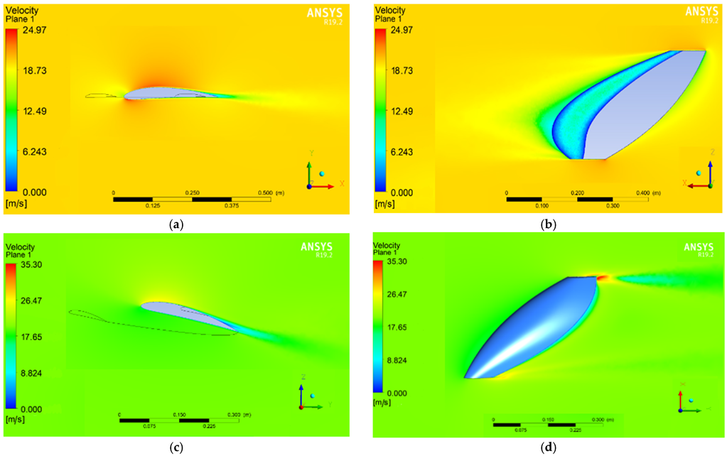
Figure 8.
Electrical diagram of the new UAV concept (hybrid quadcopter).
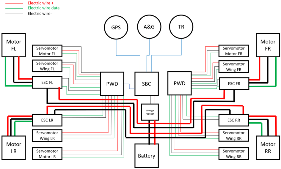
Figure 9.
Quadcopter overview—the five steps applied when the UAV is moving forward: I—lifting, II—keeping the UAV at a fixed point; III—reducing the speed at the front engines the UAV starts to bank, and the stall speed starts to increase; IV—the wings take their angle of incidence from negative to positive to achieve lift on their surface; V—increasing the forward speed.

Figure 10.
Top view and with notation of the engines.
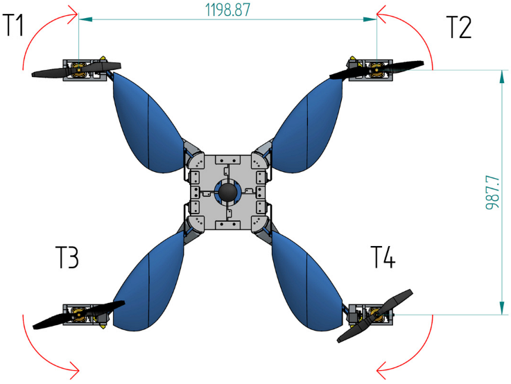
Figure 11.
Force couples in case of the UAV.

Figure 12.
Example of configuration during a travel flight.

Figure 13.
Route simulation in conventional quadcopter mode: (a) Acceleration vs. time; (b) Velocity vs. time.
Figure 13.
Route simulation in conventional quadcopter mode: (a) Acceleration vs. time; (b) Velocity vs. time.
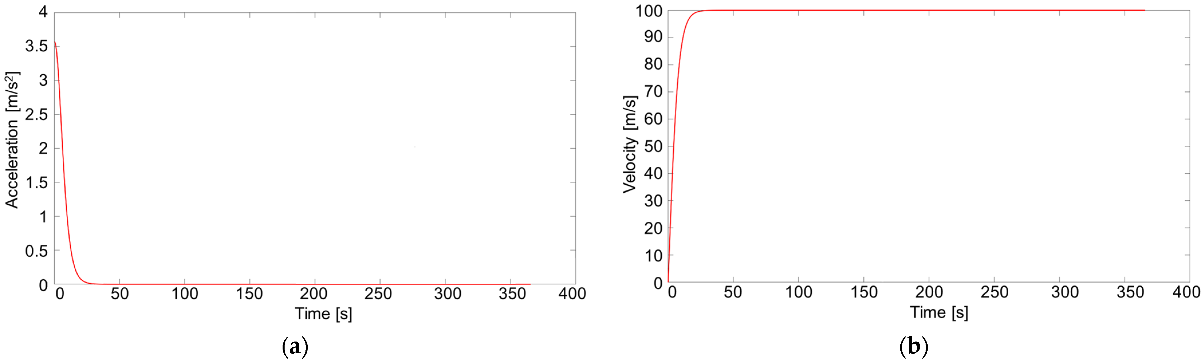
Figure 14.
Route simulation in hybrid mode with increased maximum flight speed. (a) Velocity vs. time; (b) Acceleration vs. time; (c) Tilt angle vs. time; (d) Angle of incidence vs. time.
Figure 14.
Route simulation in hybrid mode with increased maximum flight speed. (a) Velocity vs. time; (b) Acceleration vs. time; (c) Tilt angle vs. time; (d) Angle of incidence vs. time.

Table 1.
Flow simulation results.
| Velocity [m/s] | 10 | 20 | 10 | 20 | 10 | 20 | 10 | 20 | 10 | 20 |
|---|---|---|---|---|---|---|---|---|---|---|
| Angle of Incidence [°] | 0 | 3.53 | 7.05 | 10.55 | 14 | |||||
| Lift [N] | 0.42 | 1.51 | 0.82 | 3.14 | 1.26 | 4.92 | 1.73 | 6.80 | 2.20 | 8.72 |
| Drag [N] | 0.07 | 0.28 | 0.11 | 0.43 | 0.18 | 0.71 | 0.28 | 1.13 | 0.43 | 1.16 |
| Total lift [N] | 1.68 | 6.05 | 3.28 | 12.54 | 5.05 | 19.67 | 6.91 | 27.18 | 8.79 | 34.90 |
| Total drag [N] | 0.29 | 1.13 | 0.44 | 1.73 | 0.71 | 2.83 | 1.13 | 4.52 | 1.70 | 4.63 |
Disclaimer/Publisher’s Note: The statements, opinions and data contained in all publications are solely those of the individual author(s) and contributor(s) and not of MDPI and/or the editor(s). MDPI and/or the editor(s) disclaim responsibility for any injury to people or property resulting from any ideas, methods, instructions or products referred to in the content. |
© 2023 by the authors. Licensee MDPI, Basel, Switzerland. This article is an open access article distributed under the terms and conditions of the Creative Commons Attribution (CC BY) license (https://creativecommons.org/licenses/by/4.0/).
Share and Cite
MDPI and ACS Style
Frigioescu, T.-F.; Condruz, M.R.; Badea, T.A.; Paraschiv, A. A Preliminary Study on the Development of a New UAV Concept and the Associated Flight Method. Drones 2023, 7, 166. https://doi.org/10.3390/drones7030166
AMA Style
Frigioescu T-F, Condruz MR, Badea TA, Paraschiv A. A Preliminary Study on the Development of a New UAV Concept and the Associated Flight Method. Drones. 2023; 7(3):166. https://doi.org/10.3390/drones7030166
Chicago/Turabian StyleFrigioescu, Tiberius-Florian, Mihaela Raluca Condruz, Teodor Adrian Badea, and Alexandru Paraschiv. 2023. "A Preliminary Study on the Development of a New UAV Concept and the Associated Flight Method" Drones 7, no. 3: 166. https://doi.org/10.3390/drones7030166