
Toward Virtual Testing of Unmanned Aerial Spraying Systems Operating in Vineyards

Department of Mechanical and Aerospace Engineering, Politecnico di Torino, 10129 Torino, Italy
*
Author to whom correspondence should be addressed.
†
These authors contributed equally to this work.
Drones 2024, 8(3), 98; https://doi.org/10.3390/drones8030098
Submission received: 30 January 2024
/
Revised: 8 March 2024
/
Accepted: 12 March 2024
/
Published: 13 March 2024
(This article belongs to the Special Issue Feature Papers for Drones in Agriculture and Forestry Section)
Abstract
:In recent times, the objective of reducing the environmental impact of the agricultural industry has led to the mechanization of the sector. One of the consequences of this is the everyday increasing use of Unmanned Aerial Systems (UAS) for different tasks in agriculture, such as spraying operations, mapping, or diagnostics, among others. Aerial spraying presents an inherent problem associated with the drift of small droplets caused by their entrainment in vortical structures such as tip vortices produced at the tip of rotors and wings. This problem is aggravated by other dynamic physical phenomena associated with the actual spray operation, such as liquid sloshing in the tank, GPS inaccuracies, wind gusts, and autopilot corrections, among others. This work focuses on analyzing the impact of nozzle position and liquid sloshing on droplet deposition through numerical modeling. To achieve this, the paper presents a novel six degrees of freedom numerical model of a DJI Matrice 600 equipped with a spray system. The spray is modeled using Lagrangian particles and the liquid sloshing is modeled with an interface-capturing method known as Volume of Fluid (VOF) approach. The model is tested in a spraying operation at a constant velocity of 2 m/s in a virtual vineyard. The maneuver is achieved using a PID controller that drives the angular rates of the rotors. This spraying mission simulator was used to obtain insights into optimal nozzle selection and positioning by quantifying the amount of droplet deposition.
1. Introduction
In several Asian countries, Unmanned Aerial Spraying Systems (UASSs) have grown considerably over the past 30 years. This trend started in Japan and spread to South Korea, China, and now worldwide. The first studies focused on flat rice and corn canopies in agricultural research. The main goal of these studies was to obtain an even spread and the best penetration. Even though agricultural spraying techniques have improved, spray drift is still a big problem. Drift occurs when fine Plant Protection Product (PPP) droplets are spread beyond their intended target. This problem has become very important in the context of pesticide risk assessment. Many researchers have looked into the factors that affect this phenomenon and its modeling, analyzing the type of nozzle, injection pressure, and wind speed for ground and aerial operations [1,2,3,4,5].
The case of three-dimensional crops, typically arranged in rows, such as orchard trees, creates additional challenges. In the case of this particular canopy, there is an elevated likelihood of off-target losses into the inter-row region. Therefore, it is imperative to thoroughly examine the impact of various flight and spray parameters on achieving the required pesticide distribution and canopy penetration for diverse crops, as evidenced by several studies [6,7,8,9]. Optimizing how sprays are used in vineyards is an interesting topic because the land is sloped and uneven, and the vines are planted in long, narrow rows. Sarri [10] analyzes this scenario. The circumstances above present numerous obstacles, leading to complex precision spraying procedures and emphasizing the significance of the flight mode in optimizing product deposition on the crop, while simultaneously reducing drift towards the inter-row area. The article by Biglia [11] looks at how different operational parameters affect spray coverage and deposition in vineyards.
The interaction between spray and rotors has been experimentally tested both in the open field [12] and in wind tunnel facilities [13,14,15], where the authors investigate drift with varying wind speed, spray volume, and nozzle characteristics. Drift is also addressed in [16], where the authors survey solutions to reduce the inevitable drift by optimizing the rotor, nozzle setup, spray system, and flight parameters. Concurrent with experimental investigations, numerical simulations have examined the downwash flow characteristics of multi-rotor systems. The study presented in [17] employs a lattice Boltzmann methodology to investigate the wake characteristics of a hexacopter used for plant protection. Additional computational methodologies encompass the examination of droplet trajectories by utilizing a Dispersed Phase Model (DPM), as evidenced in the works of [18,19,20]. The Lagrangian particle model relies on injection inputs, including droplet diameter, momentum, and spray angle, which are challenging to predict with precision and are a priori unknown. The inputs may be predicted using experimental approaches [1], empirical approximations [21], and numerical simulations [22,23]. The previous computational works were performed using a volume-of-fluid (VOF) approach. With an adequate estimation of the input parameters, the Lagrangian model can model the spray drift and is becoming popular in computational approaches such as in [14,24,25], which present qualitative and quantitative validation studies. Apart from validation studies, Chen [25] also presents an optimization based on Radial Basis Functions (RBF) to explore optimal nozzle positioning.
Despite everyday growing research regarding the use of computational tools to estimate, analyze, and optimize drift problems, some of the key parameters that drive the actual operation of aerial spraying missions are typically neglected. These include the presence of crosswind, liquid sloshing inside the tank, Global Positioning System (GPS) inaccuracies, autopilot corrections varying angular rates of the rotors, and actual pitch angle. Some of these aspects have been studied independently. Surico [26] analyzed the effect of sloshing and concluded that accelerations might affect the flight qualities of the vehicle and therefore it is advisable to use perforated plates and a dedicated control system to damp the oscillations of the liquid inside the tank. Feng [24] studied the effect of crossflow and downwash on spray systems. Ref. [27] presents a UASS adaptive control law that depends on the weather conditions. The goal of this control law is to make sure that pesticides are accurately deposited in the target. However, to the authors’ knowledge, no studies are presented in the literature numerically studying the interactional effects between different disciplines involved in unmanned aerial spraying using rotary wing vehicles.
This work aims to close the aforementioned gap in the current state-of-the-art of UASS by proposing a numerical tool that allows the simulation of droplet deposition including the effects caused by sloshing and UAS dynamics. This paper follows from our previous publication [14], in which we validated a numerical model to predict droplet deposition in a wind tunnel facility. This model was embedded in a dynamic simulation framework [28] that allows the reproduction of multicopter maneuvers following a Proportional–Integral–Derivative (PID) controller. The scenario chosen for this work is the vineyard and we aimed to mimic the characteristics in which the spray missions presented by Biglia [11] were carried out using the same multicopter, a DJI Matrice 600 and the same spray system, originally developed for the wind tunnel testing presented in [14]. In this paper, we focus on a flight mode parallel to the vine row direction at 2 m/s.
2. Materials and Methods
2.1. DJI Matrice 600 and Spray System
The DJI Matrice 600 (DJI, Shenzhen, China) was chosen as our reference UAS, as this was used in the wind tunnel tests presented in [14,29] and used in the flight tests presented in [11,30]. It has a recommended Maximum Take-Off Weight (MTOW) of kg, and its main characteristics are reported in Figure 1 and Table 1. As shown in Figure 1, the drone operates with its nose, represented with red motors (M1–M2), rotated clockwise by 30° with respect to the local wind direction.
A dedicated spray system was manufactured according to the circuit presented in Figure 2, and includes a remote-control system to switch the pump on and off. The system contains a battery, a membrane pump, a pressure regulator, a pressure gauge, and two nozzles for a total weight of approximately kg. Two nozzles’ holders (N1 and N2) are installed under the rotors M2 (leading) and M5 (rear), as evidenced in Figure 1. In this figure, the coordinate system (x, y, z) represents the body axes, complying with the reference frame that the DJI company specifies for the flight controller. This axis will be different from the axis used for our controller, defined in Figure 3. The UASS is rotated clockwise by 30° because, in this application, the nozzles must be precisely above the vine rows and therefore aligned with the wind direction.
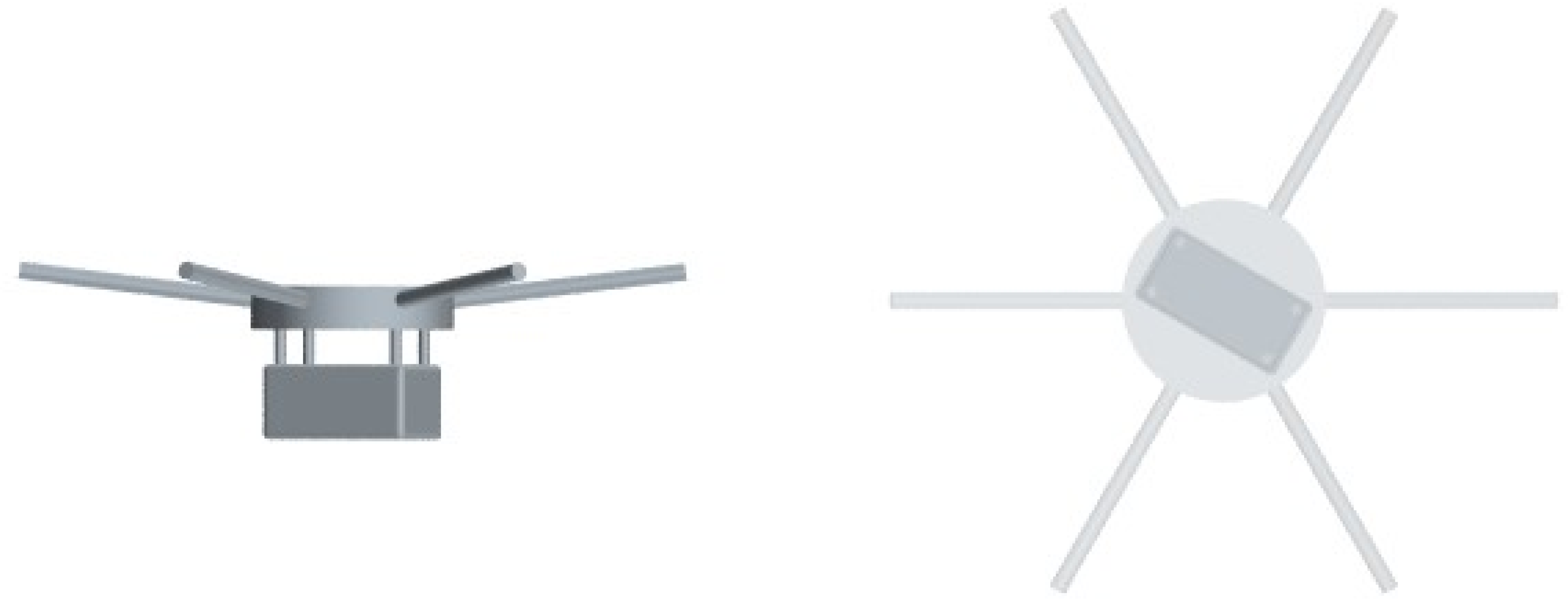
A simplified CAD model compliant with the aforementioned UAS and Spray system was developed. The reconstructed model, shown in Figure 4, clearly shows how the simplified geometry consists of the arms, the body, and the tank. The rotors are not modeled as the flow induced by them will be reproduced using a body-force propeller model which does not require the resolution of the geometry.
The UAS mounted Tmotor 15″ × 5″ blades in the wind tunnel test presented in [14]. However, these blades could not provide enough thrust for flight tests, and they were replaced with a DJI 21″ × 7″ folding propeller (DJI 2170R). The thrust and torque coefficients of these blades are unknown. For simplicity, we scaled the coefficients ( and ) of the T-Motor to a higher diameter as the relative pitch is equivalent. For a detailed analysis, these should be accurately computed using CFD simulations or using manufacturers’ data. However, the authors recommend using the latter with care, as they are not always accurate.
2.2. Hexacopter Dynamics and Control
Simcenter STAR-CCM+ calculates the body’s motion in response to the fluid forces and moments at the coupled boundary. The effect of the motion of the rigid body on the fluid is accounted for by moving the entire fluid mesh rigidly. Simcenter STAR-CCM+ calculates the resultant force and moment acting on the body due to user-defined forces and moments and the fluid’s pressure and shear forces.
The resultant force and moment acting on the body can be written as:
where represents user-defined forces and represents user-defined moments, which you can define directly or as the result of user-defined forces. In this work, these external forces and moments will be associated with the forces and moments produced by the rotors and the sloshing of the liquid inside the tank. The sloshing forces and moments are calculated by integrating the pressure distribution and shear stresses on the internal walls of the tank. is the gravity force. and are the fluid pressure force and moment acting on the body. and are the fluid shear force and moment, respectively.
For a single body with no kinematic restrictions present, we retrieve the classical 6-DOF free-body solver. The linear and angular momentum conservation laws shown below are integrated in this case.
In this work, the UAS has zero initial velocity and the initial position of its center of mass is 3 m above the ground to avoid simulating an additional segment. The dynamic solver includes temporal sub-stepping to enable an accurate solution despite the relatively large time step used in our simulation.
A PID controller is implemented to test the effectiveness in combination with CFD simulations, not forgetting the limit of the computational cost. This control law is popular because of its simplicity, robustness, and effectiveness in forcing the controlled variable y(t) to follow as closely as possible a reference variable r(t) defined by the guiding law [31]. As a feedback control, the system acquires the measurement of the controlled variable to stabilize the system, reducing the error e(t) = r(t) − y(t) between the reference and the measured variable. The control signal u(t) becomes
where is the proportional gain, is the integral gain, and is the derivative gain. Moreover, adjusting these control parameters to reach the reference in a finite time is relatively easy to accomplish the required performance in terms of stability, steady-state error, and convergence time.
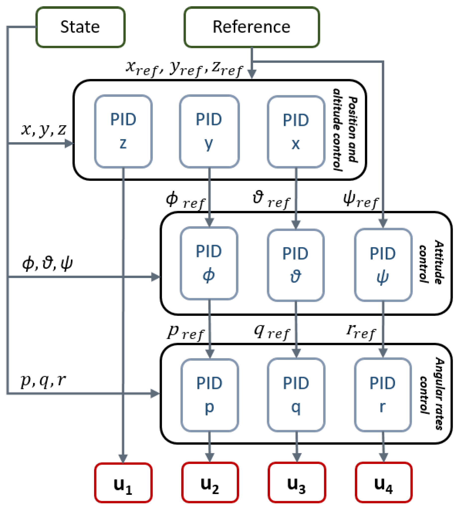
A robust cascade PID control algorithm to track position (altitude and lateral), forward speed along the vine row, and the yaw angle (, , , ) has been developed, as shown in Figure 5. Inputs to the control logic are (x, y, z), (, , ) and (p, q, r) in body frame. Sensors and noises are not considered in this model.
This control algorithm was validated for a quadrotor model in [28], the different dispositions and number of rotors of the DJI Matrice 600 require a modification in the motor mixer. The rotor positions, orientation, and body axis are shown in Figure 3. This set of equations, known as the motor mixer, maps the control required force and moments with the rotational speeds. Considering a planar configuration, these can be expressed as
Apart from the additional rotors, this hexacopter presents the complication of not being planar. The arms, of length m, have an inclination, of around 7 degrees. This slightly complicates the rectangular matrix shown in Equation (5). The new formulation of this matrix, M, is
where and represent the cosine and sine of the arms tilt angle. Furthermore, we can appreciate how our system is underdetermined. This system will have infinite combinations of the angular velocities that solve the problem. Of these solutions, we would like to select the minimum norm solution, as this would reduce the power employed in the control. Therefore, we can compute the square of the angular velocities as
where C is a vector containing the control force and moments, and denotes the Penrose–Moore Pseudoinverse of matrix presented in Equation (6).
In this case, we aim to spray at a constant velocity as this is a critical variable influencing spray drift and mission effectiveness. To this purpose, we control velocity instead of controlling position for the x direction (aligned with the row). In this way, the controller will attempt to adjust the pitch angle to achieve a constant velocity in the direction of the row. The control system in this work operates at a frequency of 100 Hz.
2.3. Virtual Vineyard
Figure 6 shows the reference vineyard that will be used in this study. It must be noted that this is only one of the many configurations that can be found. These measures are coherent with the experimental study involving flight tests using our UAS and spray system presented by Biglia [11]. Figure 7 shows the geometry used in our numerical model, which respects the aforementioned configuration. We can see how the leaves forming the vine plant have different orientations, and their geometry is simplified and with an unrealistic thickness. Possibly, one of the biggest inaccuracies of the model resides in modeling leaves as rigid solids. The flapping of the leaves observed experimentally probably enhances the penetration of PPP into the plant. Nevertheless, the model can distinguish the number of droplets deposited on the leaves from those in the inter-row region, and allows for a physically compliant flow blockage. The particles that end up in the inter-row region are the ones that we aim to minimize.
2.4. CFD Model
The developed numerical model is based on the Unsteady Reynolds Averaged Navier-Stokes Equations (URANS). The finite volume solver embedded in the commercial solver STAR-CCM+ is used to resolve the fluid flow generated by the hexacopter. The low Mach numbers involved in the mission permit the use of a segregated solver using the SIMPLEC algorithm that enables a faster convergence with less memory requirement compared to density-based solvers. We use a third-order Monotonic Upwind Scheme for Conservation Laws (MUSCL) for the spatial discretization. The temporal discretization uses a first-order approximation due to the incompatibility of higher-order formulations with the multi-stepping approaches in the VOF solver for the sloshing. The chosen turbulence model is the Spallart–Allmaras described in [32].
The computational domain is presented in Figure 8 showing how the hexacopter is far away from the outer domain except for the ground that is placed at 3 m. The boundary conditions are no-slip walls for the outer walls, the UAS body, and the vineyard. The volume is sufficiently large to avoid strong unphysical recirculation effects in the time employed in completing the mission.
The rotors are modeled with the body force propeller method, a virtual disk model that allows the generation of coherent axial and swirl velocities within a RANS simulation framework based on the thrust and torque coefficients. This model adds a source term in the momentum equations associated with the virtual disk region that mimics the momentum generation produced by a rotor. The radial distribution of the axial and tangential induced velocities can be computed from the actual load distribution of the rotor under study. If this is unknown, Goldstein’s optimal thrust and torque distributions may be used. The body-force method has been widely used for the simulation of self-propelled vessels. In particular, ref. [33] uses the implementation in STAR-CCM+ for a self-propulsion case. The model can adequately compute the bulk velocities induced by a rotor in a fluid and lately, there has been interest in applying this methodology to aerial fans, rotors, and propellers with a particular interest in distributed propulsion [34,35].
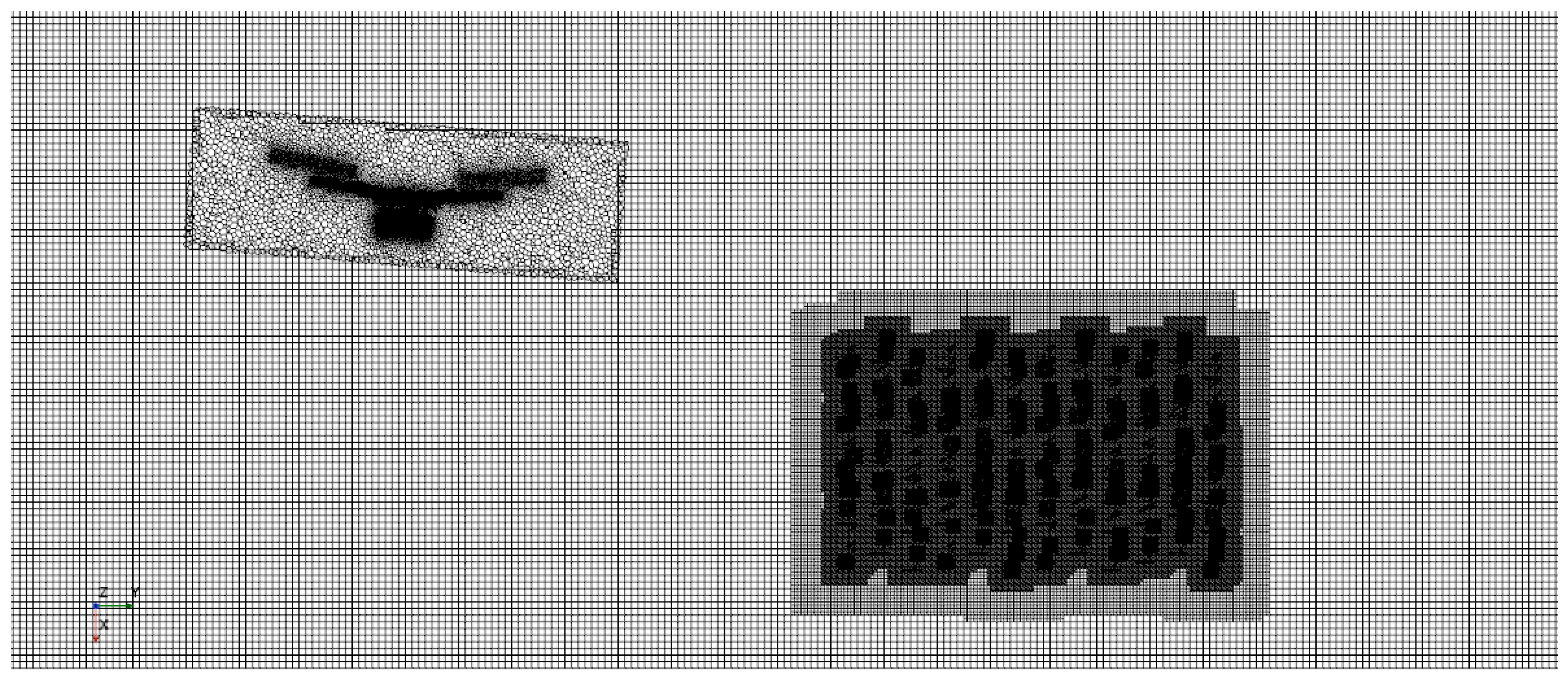
The simulation is performed in a short vineyard section around m long. The domain consists of two regions: a prismatical region containing the UAS that will change position and orientation following the 6-DOF solver and a background region. Both of these regions are connected through an overset interface. We opted for a generalized volumetric refinement adequate for a smooth transition in the overset grid interface. Figure 9 shows how our background grid uses a trimmed cell mesh, and our overset grid uses polyhedral cells to adequately resolve the vehicle geometry. A prism layer mesh with a y+ smaller than one is included around the UAS body and water tank as computing the drag is relevant to accurately predict the pitching angle. We can also appreciate how the model includes a fine mesh around the vine region to model the blockage effect the vine plant would create on the wake. The regions containing the virtual disk are also refined to enable accurate results. This refinement, however, requires a small number of cells compared with that required when the blade is resolved. An additional advantage of using a virtual disk approach is that they only model induced velocities. These velocities are found on the wake and are around an order of magnitude smaller than tip speed velocities. The cell size on the wake is also an order of magnitude larger so globally the Courant Friedrich Levy (CFL) condition for stability is relaxed by at least two orders of magnitude, allowing for stable solutions at higher time-steps. The reduction in temporal and spatial discretization requirements reduces the cost of such simulations between 2 and 3 orders of magnitude, compared with a sliding grid approach in which the rotor geometry is resolved.
A comparative study presented by the authors of [36] shows, for a similar mission involving a quadrotor, how the use of the body force propeller method generates compliant UAS dynamics and mean velocity distributions in the rotors wake with a 200-factor reduction in the computational cost. The computational cost of one simulation is 300 CPU hours using 32 cores of an Intel Xeon Scalable Processor Gold 6130 2.10 GHz at the high-performance computing facility from Politecnico di Torino (HPC@POLITO). This CPU cost is relatively low, considering the available computational resources in modern high-performance computing centers. Just to give the reader a reference, the same simulation was run in a workstation with 16 AMD Ryzen 9 processors in around 20 h. The biggest limitation for users to run these simulations is probably the RAM requirements which rise to 60 GB.
2.5. Spray Model
The spray droplets have been modeled using Lagrangian particles. The spray droplets injected in our simulations are modeled as material spherical particles. Sprays tend to generate droplet diameter distributions that may vary by an order of magnitude. This means that the inertia of these droplets will vary three orders of magnitude. This greatly impacts the drift problem, and it is important to consider this variation to estimate droplet deposition patterns.
The motion of a particle may be described by solving the linear momentum conservation law, shown in Equation (8).
where the forces acting on the particle are, from left to right, the gravity force, the virtual mass force, the drag force, the pressure gradient force, and the shear lift force. The drag coefficient proposed in [37] has been used to compute the drag force. For the calculation of the shear lift, the expression provided in [38] has been employed.
The aforementioned equation determines univocally the trajectory of the particles for a given distribution of initial conditions (velocity and diameter). However, the determination of these initial conditions is not trivial especially the initial velocity of the particles as they are dependent on the intricate geometrical details of the nozzles. Carreño Ruiz et al. [14] present a numerical and experimental procedure to estimate these initial conditions by fusing data provided by manufacturers, VOF simulations, and wind tunnel flow visualization for an HCI8002 (manufactured by ARAG Group, Düsseldorf, Germany) operating at an injection pressure of 2 bar.
In this work, the same model for the hollow cone injectors is used, in which we assume a negligible swirl velocity, a uniform initial velocity equal to the film velocity of the conical sheet of fluid ( m/s), and the droplet diameter distribution will be assumed to follow a Log-normal distribution with a mean of and a standard deviation of . The effective cone aperture angle was set to 56 degrees, as it was shown that the influence of an axial velocity caused by the rotor at around 12 m/s reduces the aperture angle. The resultant model is shown in Figure 10.
To analyze the effects of spray drift, we created also a 40 degree hollow cone nozzle model by hypothesizing that all the parameters will remain constant except the effective aperture angle which will be reduced proportionally to 28 degrees.
2.6. Sloshing Model
The sloshing inside the tank was modeled using the Volume of Fluid approach. This Multiphase Model pertains to the family of interface-capturing techniques for predicting the distribution and movement of the interface of immiscible phases. The mesh resolution must be sufficient for this modeling approach to resolve the location and shape of the interface between phases.
The distribution of the phases in the domain is determined by the volume fraction of phase i, which may be defined as
where V is the volume of a given cell, and is the volume of phase i in that cell. Therefore, the volume fraction defines the proportion of a phase. The sum of the volume fractions for all phases must add up to 1.
To calculate the evolution of the phases in the simulation, this approach solves an extra scalar transport equation for the volume fraction, as shown in Equation (10).
The Courant Friedrich Levy (CFL) number should be kept below , even for implicit time integration schemes to avoid interphase blurring. To avoid this restrictive condition on the global time step, a multi-stepping approach for the volume fraction transport equation has been used, allowing the global CFL condition to be relaxed and, thus, reducing the computational cost of the simulations. In this work, we used an implicit multi-stepping approach with 20 internal iterations to avoid interface blurring even for the large time-steps used in this simulation, which is conditioned by the large physical time required to simulate the mission in an acceptable computational time.
3. Results and Analysis
3.1. Hexacopter Dynamics Verification and Gain Scheduling
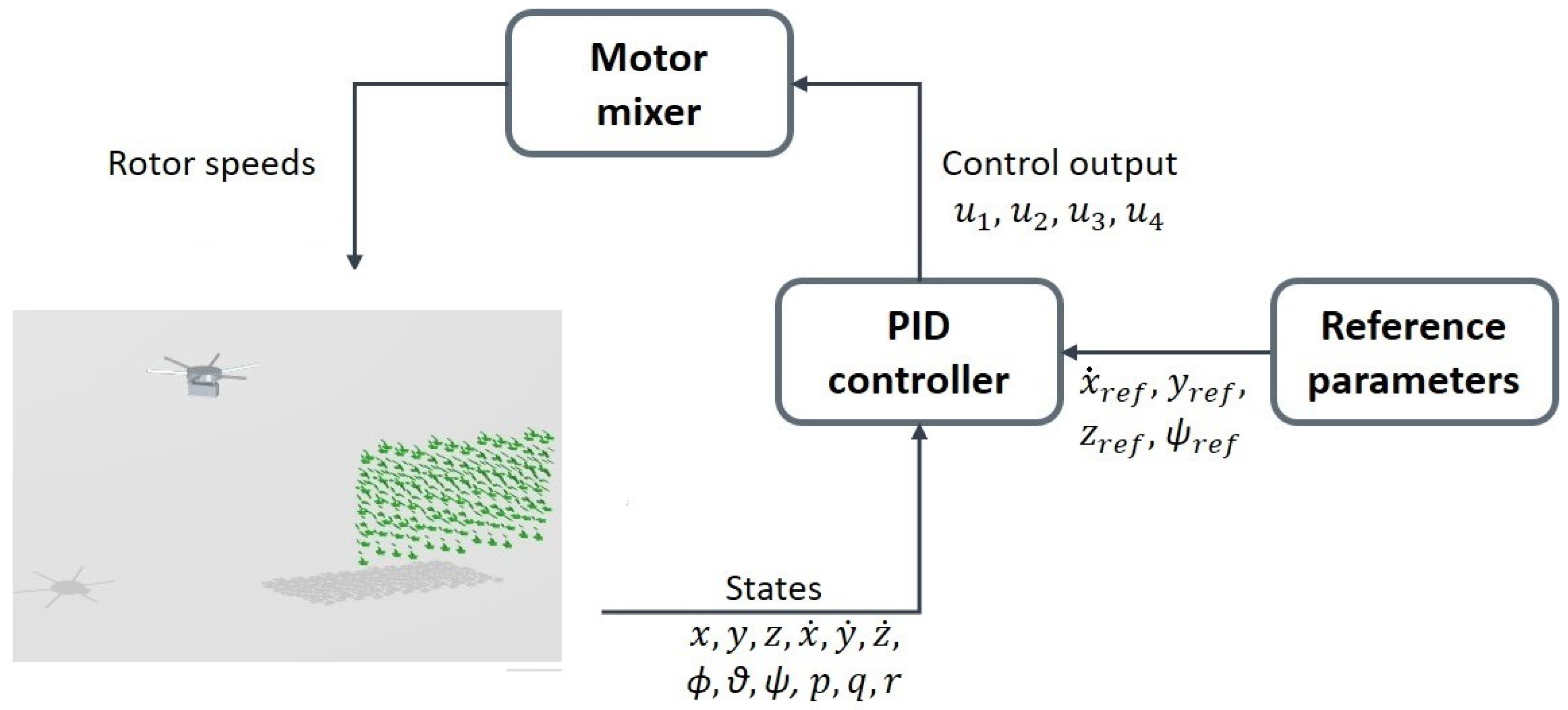
In this work, we aim to reproduce a spraying mission to assess the influence of the cone angle, orientation, and position on spray depositions. Initially, the mission is performed without the sloshing of PPP in the tank. The duration of the mission is 4 seconds. The PID controller allows the UAS to reach its target speed of 2 m/s before the start of the vine row. The velocity component along the row and the pitch angle are shown in Figure 11. This figure also includes the same maneuver simulated by a simplified MATLAB/Simulink model. For more details on this model, we refer the reader to [39]. We can appreciate how both signals are equivalent except for the asymptotic value of the pitch angle that has to remain slightly negative in the CFD model to compensate for the drag force, which is not included in the MATLAB/Simulink model. In any case, the good agreement between these two models enabled us to perform a preliminary gain scheduling using the fast MATLAB/Simulink model and also serves as a verification of the implementation of the PID in our virtual simulation framework summarized in Figure 12.
The sloshing effects have been introduced by computing the inertia and mass of the system without liquid in the tank and considering the liquid forces (including weight) and moments exerted on the tank as external actions on the system.
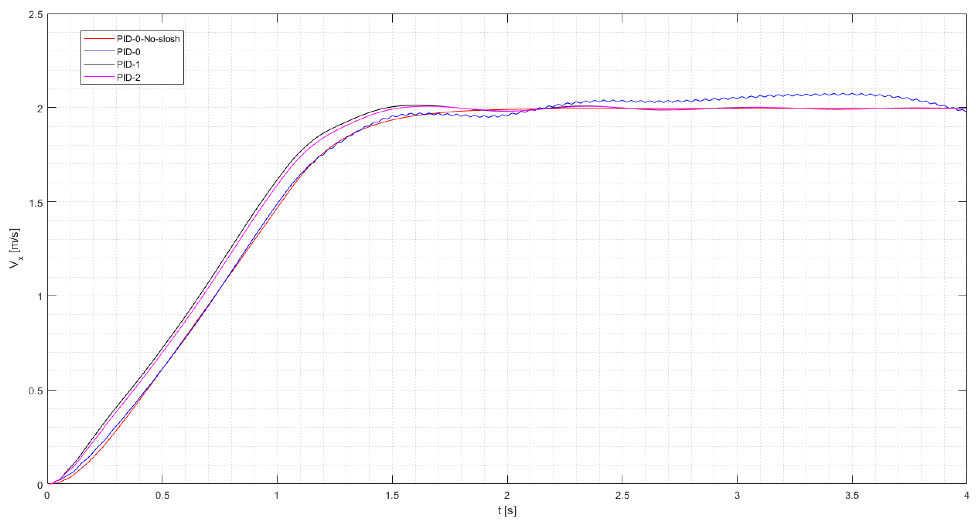
The introduction of the sloshing effects created a high-frequency oscillatory response by the controller, unable to accurately achieve a constant velocity of 2 m/s over the vineyard. The oscillations of the liquid create high alternating values of the derivative of the angular rates and saturate the pre-impost limits in rotation rates. We performed a targeted gain scheduling for the derivative terms associated with the pitch control PID. The velocity in the direction of the row () is shown in Figure 13 with the different control strategies.
We can appreciate how the PID-0 settings work fine for the no-sloshing case but have trouble achieving the 2 m/s asymptotic value presenting the aforementioned high-frequency oscillations. Strategies PID-1 and PID-2 have reduced derivative terms associated with the pitch control by 10 and 3, respectively. They show how, despite a slight overshooting in the velocity and a small residual oscillation with a frequency coherent with the sloshing frequency, they can maintain a reasonably constant velocity close to 2 m/s while flying above the vine row. The PID-2 settings will be used in the analyses that follow from this point.
Figure 14 presents snapshots at different times of the mission. The UAS starts with a horizontal position, tilts forward to achieve the desired velocity, and then progressively tilts back to the equilibrium position, which is not horizontal due to drag. While doing this, we can appreciate the liquid inside the tank sloshing creating moments not only in the pitching direction but also around the other axes due to the 30-degree misalignment between the tank and the flight direction. We can also appreciate how the vine row produces a non-negligible blockage effect in the wake velocities. The spray system is activated after 1 s. The droplets are modeled as Lagrangian particles that do not interact with the Eulerian phase. This is a noticeable advantage, as just one simulation allows studying as many spray system configurations as possible, as will be shown in the following section.
3.2. Droplet Deposition Analysis
In this section, we analyze the on-target and ground deposition of droplets injected into the flow using different modeled nozzles. In particular, we assess the angle of the nozzle, the rotor under which is positioned, and its orientation. We propose a 40 and 80-degree nominal hollow cone nozzle positioned either below the leading or rear rotor and oriented normally to the rotor or compliant with the wake. In the case of the rear rotor, the wake is aligned with the axis of the rotor so, in this case, there is no difference. On the other hand, the wake of the leading rotor is convected downstream of the flight velocity and, therefore, the axis of the rotor and the wake are not aligned. Our wake-compliant or modified orientation attempts to align the axis of the injector with the wake. For the simulated conditions, we rotated the nozzle 15 degrees downstream.
Table 2 shows the spray on-target deposition and the overall efficiency of the spraying mission. Regarding the cone angle, it seems that the 80-degree nozzle obtains a reduced efficiency of around 30%, whereas the smaller cone angles show efficiencies of around 50%, regardless of the other parameters. If we compare the leading and rear rotors, there is no clear trend with only subtle differences in efficiencies. Comparing the orientation for the 40-degree nozzles under the front rotor, we can appreciate a small drop in efficiency in the rotor’s normal configuration. This is probably caused by some droplets leaving the wake region earlier and does not benefit from the positive effect of the downwash. Finally, we also performed simulations with nozzles below the front and rear rotors simultaneously. This was performed as a sanity check to see if the number of injected Lagrangian particles was enough to obtain independent statistics. The fact that the simulations using both nozzles converge to an average value of the front and rear injectors is proof of converged statistics.
Despite the quantitative values of the efficiency of the spraying operation, it is also interesting to address where the off-target deposition concentrated is, and why it is caused. To this purpose, we present Figure 15 and Figure 16 that show the actual droplet deposition obtained with individual nozzle classified by diameters and the distribution of off-target volume along the transversal direction of the vineyard, respectively.
In particular, Figure 15 shows how the nozzles placed below the leading rotor present a strongly asymmetric distribution towards the left of the vineyard. We can also see how the larger droplets (yellow–red) follow the cone projection on the ground while smaller ones (blue–green) are more deviated and can travel larger distances. Figure 16 reveals how the particles emitted from leading injectors are prone to drift laterally to the left and, conversely, the rear injected particles tend to drift more towards the right. This is an interesting finding that the authors believe has not been thoroughly addressed in the literature. The only asymmetry in the problem derives from the rotation rates of the rotors and, therefore, this phenomenon is most probably related to this. A feasible explanation of this is the fact that the swirling flow in the wake of the rotors when impinged by the flight velocity is deflected laterally in a similar way as the Magnus effect deflects spinning objects. This causes particles to leave the influence of the wake at different instances of time, depending on the sense of rotation of the rotors. Another interesting conclusion extracted from this analysis is the smaller dispersion in the case of the rear location of rotors. Almost all the droplets are contained within 1 meter of the vineyard. Conversely, when injectors are placed below the leading rotors droplets are present even after 3 meters. The reduced lateral spray dispersion when injectors are located in the rear rotors is attributed to the more vertical wake, shown in Figure 14, due to the shielding effect of the drone body and leading rotor on the relative wind.
4. Conclusions and Future Works
This work describes the development of a multi-physics framework for the virtual testing of unmanned aerial spraying systems using STAR-CCM+, a commercial CFD software. Multicopter aerodynamics have been modeled with URANS simulations reducing the complexity and computational cost of resolving the rotors’ geometry by using a virtual disk approach. This can model the induced velocity by the rotors, which is the main actor concerning spray drift. The dynamics of the multirotor are reproduced by combining a 6-DOF model and a PID controller that allows the adjustment of the rotation rate of the rotors. The influence of the sloshing of liquid inside the PPP tank was assessed using a VOF method concluding that the impact on the UAS dynamics is relevant and that an ad hoc gain scheduling for the controller including the sloshing is necessary for operating in the tested conditions. An alternative discussed in the literature is to compartmentalize the tank with holed plates to reduce the impact of the sloshing. In any case, considering that UASS tanks represent an important fraction of the vehicle’s weight it is important to address the change in the center of mass caused by the sloshing/emptying of the tank. This will be addressed in future works.
Regarding spray deposition, the proposed approach presents the advantage of using Lagrangian particles that allow the injection of multiple independent phases in the same simulation with a negligible impact on computational cost. By injecting particles in this simulation, we can track droplet deposition both on and off-target and extract conclusions regarding the use of hollow cone nozzles for this particular mission in the vineyard scenario. The main conclusions are:
- The 40-degree hollow cone nozzles present improved efficiencies compared to the 80-degree hollow cone nozzles independent of the positions and orientation.
- The ground deposition reveals a laterally asymmetric distribution depending on the rotor handedness. This could be a relevant effect to consider for the development of adaptive path-planning strategies that might not fly in the middle of the vineyard and could also include the effect of crosswind.
- The rear rotor presents a much smaller lateral dispersion. The more vertical wake allows more momentum from the wake to be communicated to the particles reducing the ground imprint. Considering that PPPs are typically harmful, this is an interesting advantage compared to the leading rotor location, especially in the presence of crosswinds.
- In the tested case, the wake-compliant orientation of the nozzle increased the efficiency of the operation and reduced the lateral dispersion, showing that there is still room for the reduction of the spray drift and demonstrating that the downwash of the rotors has a positive effect on spray drift.
The presented framework has enabled us to extract conclusions regarding the spray drift problem, which would have been difficult and expensive to perform experimentally with the use of water-sensitive paper. This methodology tracks particles in position and time and allows for a quantitative calculation of the efficiency of the spray operation.
The framework is general and can be modified for different missions and requirements. This research activity presents some strong simplifications, such as the rigid nature of the leaves, the fact that we assume that all the droplets that impact a leave will stick to it, or the virtual disk model. The rigid modeling of the leaves is a necessary simplification due to the extreme complexity of modeling the flapping and deformable nature of the leaves. On the other hand, the other two aforementioned simplifications can be enhanced by fine-tuning the model with higher fidelity numerical data and experiments. Despite the simplifications, the model allows us to capture interesting physical phenomena related to aerial spraying and poses itself as an interesting tool for the plan of experiments and flight tests.
Our future efforts will focus on the validation of the framework and enhancing the embedded models. Special attention will be given to the implementation of an adaptive path-planning algorithm under cross-wind conditions. Finally, introducing canopy size parameters as variables influencing droplet deposition will be considered to enrich the potential applications and fidelity of the virtual testing model.
Author Contributions
Conceptualization, M.C.R., N.B., G.G. and D.D.; methodology, M.C.R., N.B., G.G. and D.D.; software, M.C.R., N.B. and D.D.; validation, M.C.R. and N.B.; formal analysis, M.C.R. and N.B.; investigation, M.C.R., N.B., G.G. and D.D.; resources, M.C.R., N.B., G.G. and D.D.; data curation, M.C.R. and N.B.; writing—original draft preparation, M.C.R. and N.B.; writing—review and editing, G.G. and D.D.; visualization, M.C.R. and N.B.; supervision, G.G. and D.D.; project administration, G.G.; funding acquisition, G.G. All authors have read and agreed to the published version of the manuscript.
Funding
This research activity relies on funds from the project “New technical and operative solutions for the use of drones in Agriculture 4.0” (Italian Ministry of University and Research-Progetti di Ricerca di Rilevante Interesse Nazionale–PRIN 2017, Prot. 2017S559BB).
Data Availability Statement
The raw data supporting the conclusions of this article will be made available by the authors on request.
Conflicts of Interest
The authors declare no conflicts of interest.
Abbreviations
The following abbreviations are used in this manuscript:
| UAS | Unmanned Aerial System |
| UASS | Unmanned Aerial Spraying System |
| CFD | Computational Fluid Dynamics |
| PA | Precision Agriculture |
| DPM | Dispersed Phase Model |
| RBF | Radial Basis Functions |
| VOF | Volume Of Fluid |
| MTOW | Maximum Take-Off Weight |
| URANS | Unsteady Reynolds-Averaged Navier–Stokes |
| CSF | Continuum Surface Force |
| CFL | Courant Friedrich Levy |
| CAD | Computer-Aided Design |
| PPP | Plant Protection Product |
| GPS | Global Positioning system |
References
- Nuyttens, D.; Baetens, K.; De Schampheleire, M.; Sonck, B. Effect of nozzle type, size and pressure on spray droplet characteristics. Biosyst. Eng. 2007, 97, 333–345. [Google Scholar] [CrossRef]
- Chen, S.; Lan, Y.; Zhou, Z.; Ouyang, F.; Wang, G.; Huang, X.; Deng, X.; Cheng, S. Effect of droplet size parameters on droplet deposition and drift of aerial spraying by using plant protection UAV. Agronomy 2020, 10, 195. [Google Scholar] [CrossRef]
- Ahmad, F.; Qiu, B.; Dong, X.; Ma, J.; Huang, X.; Ahmed, S.; Chandio, F.A. Effect of operational parameters of UAV sprayer on spray deposition pattern in target and off-target zones during outer field weed control application. Comput. Electron. Agric. 2020, 172, 105350. [Google Scholar] [CrossRef]
- Wang, G.; Han, Y.; Li, X.; Andaloro, J.; Chen, P.; Hoffmann, W.C.; Han, X.; Chen, S.; Lan, Y. Field evaluation of spray drift and environmental impact using an agricultural unmanned aerial vehicle (UAV) sprayer. Sci. Total Environ. 2020, 737, 139793. [Google Scholar] [CrossRef] [PubMed]
- Djouhri, M.; Loubet, B.; Bedos, C.; Dages, C.; Douzals, J.P.; Voltz, M. ADDI-Spraydrift: A comprehensive model of pesticide spray drift with an assessment in vineyards. Biosyst. Eng. 2023, 231, 57–77. [Google Scholar] [CrossRef]
- Meng, Y.; Su, J.; Song, J.; Chen, W.H.; Lan, Y. Experimental evaluation of UAV spraying for peach trees of different shapes: Effects of operational parameters on droplet distribution. Comput. Electron. Agric. 2020, 170, 105282. [Google Scholar] [CrossRef]
- Martinez-Guanter, J.; Agüera, P.; Agüera, J.; Pérez-Ruiz, M. Spray and economics assessment of a UAV-based ultra-low-volume application in olive and citrus orchards. Precis. Agric. 2020, 21, 226–243. [Google Scholar] [CrossRef]
- Wang, C.; Herbst, A.; Zeng, A.; Wongsuk, S.; Qiao, B.; Qi, P.; Bonds, J.; Overbeck, V.; Yang, Y.; Gao, W.; et al. Assessment of spray deposition, drift and mass balance from unmanned aerial vehicle sprayer using an artificial vineyard. Sci. Total Environ. 2021, 777, 146181. [Google Scholar] [CrossRef]
- Li, X.; Giles, D.K.; Niederholzer, F.J.; Andaloro, J.T.; Lang, E.B.; Watson, L.J. Evaluation of an unmanned aerial vehicle as a new method of pesticide application for almond crop protection. Pest Manag. Sci. 2021, 77, 527–537. [Google Scholar] [CrossRef]
- Sarri, D.; Martelloni, L.; Rimediotti, M.; Lisci, R.; Lombardo, S.; Vieri, M. Testing a multi-rotor unmanned aerial vehicle for spray application in high slope terraced vineyard. J. Agric. Eng. 2019, 50, 38–47. [Google Scholar] [CrossRef]
- Biglia, A.; Grella, M.; Bloise, N.; Comba, L.; Mozzanini, E.; Sopegno, A.; Pittarello, M.; Dicembrini, E.; Alcatrão, L.E.; Guglieri, G.; et al. UAV-spray application in vineyards: Flight modes and spray system adjustment effects on canopy deposit, coverage, and off-target losses. Sci. Total Environ. 2022, 845, 157292. [Google Scholar] [CrossRef]
- Zhan, Y.; Chen, P.; Xu, W.; Chen, S.; Han, Y.; Lan, Y.; Wang, G. Influence of the downwash airflow distribution characteristics of a plant protection UAV on spray deposit distribution. Biosyst. Eng. 2022, 216, 32–45. [Google Scholar] [CrossRef]
- Liu, Q.; Chen, S.; Wang, G.; Lan, Y. Drift Evaluation of a Quadrotor Unmanned Aerial Vehicle (UAV) Sprayer: Effect of Liquid Pressure and Wind Speed on Drift Potential Based on Wind Tunnel Test. Appl. Sci. 2021, 11, 7258. [Google Scholar] [CrossRef]
- Carreño Ruiz, M.; Bloise, N.; Guglieri, G.; D’Ambrosio, D. Numerical Analysis and Wind Tunnel Validation of Droplet Distribution in the Wake of an Unmanned Aerial Spraying System in Forward Flight. Drones 2022, 6, 329. [Google Scholar] [CrossRef]
- Wang, G.; Zhang, T.; Song, C.; Yu, X.; Shan, C.; Gu, H.; Lan, Y. Evaluation of Spray Drift of Plant Protection Drone Nozzles Based on Wind Tunnel Test. Agriculture 2023, 13, 628. [Google Scholar] [CrossRef]
- Chen, P.; Douzals, J.P.; Lan, Y.; Cotteux, E.; Delpuech, X.; Pouxviel, G.; Zhan, Y. Characteristics of unmanned aerial spraying systems and related spray drift: A review. Front. Plant Sci. 2022, 13, 870956. [Google Scholar] [CrossRef] [PubMed]
- Zhang, H.; Qi, L.; Wu, Y.; Musiu, E.M.; Cheng, Z.; Wang, P. Numerical simulation of airflow field from a six–rotor plant protection drone using lattice Boltzmann method. Biosyst. Eng. 2020, 197, 336–351. [Google Scholar] [CrossRef]
- Yang, F.; Xue, X.; Cai, C.; Sun, Z.; Zhou, Q. Numerical simulation and analysis on spray drift movement of multirotor plant protection unmanned aerial vehicle. Energies 2018, 11, 2399. [Google Scholar] [CrossRef]
- Wen, S.; Han, J.; Ning, Z.; Lan, Y.; Yin, X.; Zhang, J.; Ge, Y. Numerical analysis and validation of spray distributions disturbed by quad-rotor drone wake at different flight speeds. Comput. Electron. Agric. 2019, 166, 105036. [Google Scholar] [CrossRef]
- Wang, L.; Xu, M.; Hou, Q.; Wang, Z.; Lan, Y.; Wang, S. Numerical verification on influence of multi-feature parameters to the downwash airflow field and operation effect of a six-rotor agricultural UAV in flight. Comput. Electron. Agric. 2021, 190, 106425. [Google Scholar] [CrossRef]
- Lefebvre, A.H.; McDonell, V.G. Atomization and Sprays; CRC Press: Boca Raton, FL, USA, 2017. [Google Scholar]
- Di Martino, M.; Ahirwal, D.; Maffettone, P.L. Three-dimensional computational fluid dynamics simulation of the hollow-cone spray process: The stability of the conical liquid sheet. Phys. Fluids 2021, 33, 063301. [Google Scholar] [CrossRef]
- Laurila, E.; Roenby, J.; Maakala, V.; Peltonen, P.; Kahila, H.; Vuorinen, V. Analysis of viscous fluid flow in a pressure-swirl atomizer using large-eddy simulation. Int. J. Multiph. Flow 2019, 113, 371–388. [Google Scholar] [CrossRef]
- Feng, H.; Xu, P.; Yang, S.; Zheng, Y.; Li, W.; Liu, W.; Zhao, H.; Jiang, S. Back Pressure Generated by Downwash and Crosswind on Spatial atomization characteristics during UAV Spraying: CFD Analysis and Verification. Pest Manag. Sci. 2023, 80, 1348–1360. [Google Scholar] [CrossRef] [PubMed]
- Chen, Q.; Zhang, J.; Zhang, C.; Zhou, H.; Jiang, X.; Yang, F.; Wang, Y. CFD analysis and RBFNN-based optimization of spraying system for a six-rotor unmanned aerial vehicle (UAV) sprayer. Crop Prot. 2023, 174, 106433. [Google Scholar] [CrossRef]
- Surico, P.; Bloise, N.; Primatesta, S.; Guglieri, G. Design and Stability Analysis of an Agricultural Sprayer UAS Integrated with an Anti-Sloshing Tank. In Proceedings of the 2023 IEEE International Workshop on Metrology for Agriculture and Forestry (MetroAgriFor), Pisa, Italy, 6–8 November 2023; pp. 378–383. [Google Scholar]
- Faiçal, B.S.; Freitas, H.; Gomes, P.H.; Mano, L.Y.; Pessin, G.; de Carvalho, A.C.; Krishnamachari, B.; Ueyama, J. An adaptive approach for UAV-based pesticide spraying in dynamic environments. Comput. Electron. Agric. 2017, 138, 210–223. [Google Scholar] [CrossRef]
- Carreño Ruiz, M.; Bloise, N.; Capello, E.; D’Ambrosio, D.; Guglieri, G. Assessment of Quadrotor PID Control Algorithms using six-Degrees of Freedom CFD simulations. In Proceedings of the 2022 61st IEEE Conference on Decision and Control (CDC), Cancun, Mexico, 6–9 December 2022. [Google Scholar]
- Bloise, N.; Carreño Ruiz, M.; D’Ambrosio, D.; Guglieri, G. Wind Tunnel Testing of Remotely Piloted Aircraft Systems for Precision Crop-Spraying Applications. In Proceedings of the 2021 IEEE International Workshop on Metrology for Agriculture and Forestry (MetroAgriFor), Trento and Bolzano, Italy, 3–5 November 2021; IEEE: Piscataway, NJ, USA, 2021; pp. 378–383. [Google Scholar]
- Biglia, A.; Comba, L.; Alcatrão, L.E.; Sopegno, A.; Messina, C.; Mozzanini, E.; Bloise, N.; Guglieri, G.; Grella, M. Comparison between 60° and 30° hollow cone nozzles for targeted UAV-spray applications in vineyards. In Precision Agriculture’23; Wageningen Academic Publishers: Wageningen, The Netherlands, 2023; pp. 67–73. [Google Scholar]
- Becce, L.; Bloise, N.; Guglieri, G. Optimal Path Planning for Autonomous Spraying UAS framework in Precision Agriculture. In Proceedings of the 2021 International Conference on Unmanned Aircraft Systems (ICUAS), Athens, Greece, 15–18 June 2021; IEEE: Piscataway, NJ, USA, 2021; pp. 698–707. [Google Scholar]
- Spalart, P.; Allmaras, S. A one-equation turbulence model for aerodynamic flows. In Proceedings of the 30th Aerospace Sciences Meeting and Exhibit, Reno, NV, USA, 6–9 January 1992. [Google Scholar]
- Jin, S.; Peng, H.; Qiu, W.; Oldfield, C.; Stockdill, B. Best modeling practice for self-propulsion simulation of ship model in calm water. Phys. Fluids 2023, 35, 105129. [Google Scholar] [CrossRef]
- Pantel, H.; Falissard, F.; Dufour, G. Assessment of Reynolds-Averaged Navier–Stokes/Blade Element Theory Body Force Method for Propeller Modeling. AIAA J. 2023, 62, 758–775. [Google Scholar] [CrossRef]
- Kiffer, T.; Dufour, G.; Gojon, R.; Thollet, W.; López de Vega, L. Extension and validation of the Body Force Method to a propeller blade. In Proceedings of the AIAA AVIATION 2023 Forum, San Diego, CA, USA, 12–16 June 2023; p. 3378. [Google Scholar]
- Carreño Ruiz, M. Numerical Simulation and Aerodynamic Design of Small-Scale Rotary-Wing for Unmanned Aerial Systems in Terrestrial and Martian Applications. Ph.D. Thesis, Politecnico di Torino, Torino, Italy, 2023. Available online: https://hdl.handle.net/11583/2982720 (accessed on 1 January 2024).
- Schiller, L. Über die grundlegenden Berechnungen bei der Schwerkraftaufbereitung. Z. Vereines Dtsch. Inge. 1933, 77, 318–321. [Google Scholar]
- Sommerfeld, M. Theoretical and experimental modelling of particulate flows. VKI Lect. Ser. 2000, 6, 3–7. [Google Scholar]
- Bloise, N. Design of an Innovative Spraying System for High Precision Aerial Dispersion in Vineyards. Ph.D. Thesis, Politecnico di Torino, Torino, Italy, 2023. Available online: https://hdl.handle.net/11583/2986291 (accessed on 1 January 2024).
Figure 1.
Top view of DJI Matrice 600 (Body-Fixed axes) with nozzles aligned with wind direction.

Figure 2.
Hydraulic circuit of spraying system.

Figure 3.
Hexarotor sketch in the body frame.

Figure 4.
CAD model of the DJI equipped with spray system.

Figure 5.
Robust cascade PID position and attitude control.

Figure 6.
Sketch of a standard vineyard in which we based our numerical model.

Figure 7.
Geometry used in our numerical model.

Figure 8.
Computational domain and boundary conditions.

Figure 9.
Computational grid.

Figure 10.
Lagrangian particles injected by an 80 degrees hollow cone nozzle at 2 bar.

Figure 11.
Comparison of: (a) x-velocity and (b) for the two models.

Figure 12.
Configuration of the virtual UAS testing environment.

Figure 13.
Comparative response between sloshing and non-sloshing simulation for different PID gain scheduling strategies.
Figure 13.
Comparative response between sloshing and non-sloshing simulation for different PID gain scheduling strategies.

Figure 14.
Snapshots of the mission at different times. Velocity magnitude is shown on the UAS symmetry plane, and the particles are colored depending on their diameter. The volume fraction of water inside the tank is also presented.
Figure 14.
Snapshots of the mission at different times. Velocity magnitude is shown on the UAS symmetry plane, and the particles are colored depending on their diameter. The volume fraction of water inside the tank is also presented.

Figure 15.
Ground droplet deposition colored by diameters for nozzles: (a) 40° under leading rotor with standard orientation, (b) 40° under leading rotor with normal orientation, (c) 80° under leading rotor with standard orientation, (d) 40° under rear rotor with standard orientation, and (e) 80° under rear rotor with standard orientation. Top view.

Figure 16.
Ground droplet deposition volume for nozzles: (a) 40° under leading rotor with standard orientation, (b) 40° under leading rotor with normal orientation, (c) 80° under leading rotor with standard orientation, (d) 40° under rear rotor with standard orientation, and (e) 80° under rear rotor with standard orientation.


Table 1.
Main parameters of DJI Matrice 600.
| Parameters Description | Value |
|---|---|
| Wheelbase | 1133 mm |
| Rotor diameter | 533 mm |
| Rotor pitch | 127 mm |
| Number of rotors | 6 |
| Brushless motor | DJI 6010 |
Table 2.
Lagrangian droplet on-target deposition for different hollow cone nozzle angle, position, and orientation.
Table 2.
Lagrangian droplet on-target deposition for different hollow cone nozzle angle, position, and orientation.
| Angle [deg] | Rotor | Orientation | On-Target Deposition [Liters] | Spray Volume [Liters] | Efficiency [%] |
|---|---|---|---|---|---|
| 40 | Leading | Modified | 0.00694 | 0.0129 | 53.8 |
| 40 | Leading | Normal | 0.00614 | 0.0129 | 47.6 |
| 80 | Leading | Modified | 0.00400 | 0.0129 | 31.0 |
| 40 | Rear | Normal | 0.00614 | 0.0129 | 47.6 |
| 80 | Rear | Normal | 0.00433 | 0.0129 | 33.5 |
| 40 | Both | Modified | 0.01308 | 0.0258 | 50.7 |
| 80 | Both | Normal | 0.00830 | 0.0258 | 32.2 |
Disclaimer/Publisher’s Note: The statements, opinions and data contained in all publications are solely those of the individual author(s) and contributor(s) and not of MDPI and/or the editor(s). MDPI and/or the editor(s) disclaim responsibility for any injury to people or property resulting from any ideas, methods, instructions or products referred to in the content. |
© 2024 by the authors. Licensee MDPI, Basel, Switzerland. This article is an open access article distributed under the terms and conditions of the Creative Commons Attribution (CC BY) license (https://creativecommons.org/licenses/by/4.0/).
Share and Cite
MDPI and ACS Style
Carreño Ruiz, M.; Bloise, N.; Guglieri, G.; D’Ambrosio, D. Toward Virtual Testing of Unmanned Aerial Spraying Systems Operating in Vineyards. Drones 2024, 8, 98. https://doi.org/10.3390/drones8030098
AMA Style
Carreño Ruiz M, Bloise N, Guglieri G, D’Ambrosio D. Toward Virtual Testing of Unmanned Aerial Spraying Systems Operating in Vineyards. Drones. 2024; 8(3):98. https://doi.org/10.3390/drones8030098
Chicago/Turabian StyleCarreño Ruiz, Manuel, Nicoletta Bloise, Giorgio Guglieri, and Domenic D’Ambrosio. 2024. "Toward Virtual Testing of Unmanned Aerial Spraying Systems Operating in Vineyards" Drones 8, no. 3: 98. https://doi.org/10.3390/drones8030098