Material Impact on Diamond Machining of Diffractive Optical Structures for UV-Application


1
Leibniz Institute for Materials Engineering IWT, LFM, Badgasteiner Straße 2, 28359 Bremen, Germany
2
MAPEX Center for Materials and Processes, University of Bremen, 28359 Bremen, Germany
*
Author to whom correspondence should be addressed.
J. Manuf. Mater. Process. 2018, 2(1), 15; https://doi.org/10.3390/jmmp2010015
Submission received: 5 February 2018
/
Revised: 26 February 2018
/
Accepted: 27 February 2018
/
Published: 1 March 2018
(This article belongs to the Special Issue Precision Manufacturing)
Abstract
:This paper discusses the impact of different machining parameters on structuring quality in a diamond turning process for the machining of diffractive optical elements (DOEs). Special attention is paid to the impact of the material on the geometric structuring quality. First, the machining process for DOEs is described. The structuring process is based on a face turning process combined with a nano Fast Tool Servo (nFTS), which varies the depth of cuts within a range of up to 1 μm at a maximum frequency of 5 kHz. The diamond tools being used exhibit customized rectangular tool geometry with a tool width of 10–20 μm. To determine the material impact and the influence of several machining parameters, different structures have been machined, and their geometric and topographic quality has been analyzed.
1. Introduction
Submicron optical structures are used in various fields of light modulation, such as beam shaping or beam homogenization. One example of this kind of optical component is diffractive optical elements (DOEs), which can be applied, inter alia, for spectroscopic gratings, security features on banknotes, or high-performance optical instruments [1]. The functionality of DOEs is based on the physical principle of diffraction, which describes the deflection of light at an obstacle, with size scales comparable to its wavelength. Depending on the size scale, geometry, and complexity of the desired structure, different manufacturing processes are applied. The machining of DOEs in an ultraprecision diamond turning process, compared to common lithography or laser machining, delivers high efficiency and precision at relatively low costs [2,3]. At the same time, the cutting process offers a very large spectrum of machinable geometry and component size [4]. While ultraprecision mirrors with spherical or aspherical shapes are commonly produced by diamond turning, more complex structure geometries require additional machining components. In this case, a face turning process is combined with a nano Fast Tool Servo (nFTS), which varies the depth of cuts in an ultrasonic range and in the scale of several nanometers [5]. The resulting surface consists of diffractive structure elements with rectangular shape and specific height levels. The generated structure is capable of modulating the phase of an incoming laser beam and reflecting a defined holographic image on the reconstruction plane [6]. The surface can then be referred to as a diamond turned hologram (DTH).
For the optical functionality of the workpiece, the basic geometric features of the structure elements are essential: the structure size correlates with the amount of modulated light. Structure defects and roughness can interfere with the incoming, and the reflected, light, causing disturbance in the reconstruction. In previous investigations, the tool width has been proven to be the main criterion for the choice of feed. It has been shown that a feed larger than the tool width will lead to burr formation, while a feed too small will cause unequal structure sizes [5].
Another important aspect in the machining of DTHs is the choice of workpiece material. Chemical properties, such as the affinity for the carbon of ferrous metals, exclude many metallic materials for diamond turning processes. This applies to steel, which shows tremendous tool wear caused by the chemical reactions in the cutting zone [7]. For this reason, mainly non-ferrous materials are applied in diamond machining. Among others, aluminum alloys, copper and copper alloys, brass, nickel silver, and electroless nickel are well established [8]. The latter shows an amorphous structure and isotropic properties that lead to a regular surface topography. However, the high hardness causes significant tool wear, which makes electroless nickel unsuitable for cutting processes with long machining times [9]. Based on defined requirements such as UV reflectivity, structure accuracy, and high surface finish, three materials have been chosen, whose machinability in a diamond turning process have been proven in principle.
In this paper, the applicability of ultrafine-grained aluminum, nickel silver, and brass are analyzed regarding their machinability of complex diffractive structures. Because all the selected materials are crystalline materials, the grain structure and their anisotropic behavior can affect the surface topography [10]. In the case of ultrafine-grained aluminum, a nanocrystalline grain structure has been selected in order to reduce the influence of anisotropic grain properties. A detailed investigation of the applicability of these materials in diffractive micro-structuring is required.
2. Machining Process
The manufacturing process is based on a face turning process. In order to generate defined structures on the workpiece surface, the process kinematics have to be chosen specifically. The diamond tools have a rectangular shape and tool widths of 10 and 20 μm, respectively. The principle cutting process is superimposed by the nFTS normal motion.
The nFTS is able to modulate the depth of cut ap,nFTS with a frequency of 5 kHz, showing a maximum stroke of 1 μm and a positioning accuracy of 4 nm (cf. Figure 1). The specific height level of each structure element is dictated by an optical design previously calculated by specifically developed algorithms [6]. The height modulation conducted by the nFTS is initiated by the angular spindle position, indicated by the encoder signal of the C-axis. This procedure ensures a precise positioning of each structure element, resulting in up to 2000 diffractive structure elements per revolution.
For the optical functionality of the DTH, the geometric precision of the structure element is essential. Regarding the transition between two structure elements, different effects can be observed, depending on the direction under consideration. In the cutting direction, the clearance angle of the diamond tool is mapped onto the surface when the tool plunges into the workpiece material. To keep the angle as large as possible, a tool with a clearance angle of α = 20° was chosen for the experiments. For stability reasons, the clearance angle cannot be enlarged. Regarding the retracting tool movement, the dynamics of the nFTS are the limiting factor for the steepness of the resulting structure edge. The nFTS exhibits a fast, but limited retraction speed, which causes a surface gradient at the end of a structure element, smaller than the intended 90° angle (cf. Figure 1).
In previous investigations, the position accuracy of the nFTS as well as the influence of the feed on the structure width and burr formation has been examined [5]. It has been shown that the nFTS can be used in open-loop control due to the negligible hysteresis of the piezo ceramic actuator. The deviation of the nominal stroke was assessed by optical measurements and by evaluating the machined structures. In these measurements, a deviation of 2.6 nm was determined, with a maximum of 6.8 nm, which is slightly higher than the manufacturer specification but still sufficient for the machining of diffractive structures [5].
In the feed direction, the structure width mainly depends on the chosen feed. Meier describes in [5], how the choice of the feed can affect the structure width as well as burr formation. The feed has to be several hundred nanometers less than the tool width wt in order to avoid burr formation. In this case, the structure width of a lower structure element will be slightly smaller than the elevated structure elements [5].
As mentioned before, three different materials have been investigated. The first material is ultrafine-grained aluminum, which consists of pure aluminum and has been prepared by equal-channel angular pressing. Due to its fine-grained structure with a grain size of less than 0.4 μm, the material is ductile, and side flow and grain boundary-induced roughness can be reduced [11]. In a diamond turning process, excellent surface finish can be accomplished, which makes it applicable for the machining of continuous mirrors [2] as well as microstructures such as micro-lens arrays [12]. For the machining of sharp edges without burr formation, however, aluminum is less appropriate [13].
Nickel silver and brass show high hardness and good machinability and thus are qualified for the production of mold inserts and tool molds [14]. Both have similar material characteristics, but nickel silver shows a lower ductility, which further improves the machinability of the material [15]. Due to its corrosion resistance, nickel silver is particularly suitable for mass production by replication [14].
Because of the optical application as DTH, a sufficient reflectivity of UV radiation is essential, too. In [16], the applicability of ultrafine-grained aluminum as well as nickel silver has been investigated. In these studies, nickel silver showed a relatively low reflectivity of less than 40%, while ultrafine-grained aluminum verified a high UV reflectivity of nearly 80% in experimental research.
3. Experimental Investigations and Results
3.1. Experimental Setup
The cutting experiments were conducted on a Nanotech 350FG ultra precision machine tool, situated in a temperature-controlled environment, stabilized to 20 ± 0.1 °C with a constant humidity of 50 ± 5% (cf. Figure 2). For lubrication and chip removal, the machine was equipped with an oil spray mist. The underlying processing type was a face turning process, and the air bearing main spindle ran in spindle mode with 100 rpm.
The rectangular shaped diamond tools for structuring have widths from 10 to 20 μm; the characteristics of the diamond tools are summarized in Table 1. In order to choose a feed in accordance to the tool width wt, the tools were inspected by a light microscope (cf. Figure 3a). The cutting edge was measured by an atomic force microscope (AFM) before the experiments and showed a cutting edge radius of 0.1 μm (cf. Figure 3b,c).
In order to investigate the impact of the material on the generated complex structure element and the applicability for generation of DTHs, three non-ferrous crystalline metals have been examined: nickel silver, brass, and pure ultrafine-grained aluminum (Al-UFG). The mechanical properties of the investigated materials are shown in Table 2.
The face of each workpiece was previously machined with a radius diamond tool with a nose radius of 0.762 mm in order to provide an even basis for the experiments and keep repeatable machining conditions. The resulting surface showed a kinematic roughness of 3 nm.
3.2. Impact of Materials on Structure Width and Burr Formation
Because of the rectangular shape of the diamond tool, the structure width is directly dependent on the feed as well as the tool width (cf. Figure 5). In initial experiments, the influence of the workpiece material on the structure width was investigated. In this case, the depth of cut ap,nFTS was alternated by each workpiece rotation by about 350 nm. The tool width had been measured previously by a light microscope with a 1000× magnification and a resolution of 0.1 6μm. For the determination of the tool width, in each case, three measurements were averaged. The experiments were carried out with two different diamond tools with a measured width of wt = 11.7 μm and wt = 21.5μm. For clarity, only results conducted with the latter tool are described below.
In order to prevent burr formation, for the initial experiments, the feed was 0.5 μm smaller than the measured tool width. As this leads to unequal structure sizes (cf. Figure 4a), the experiments were repeated with a feed f = 21.5 μm = wt, so that the feed matched the tool width (cf. Figure 4b). It can be seen that the upper structure width is approximately equal for both feeds. This suggests that the actual tool width might have been slightly smaller than measured with the white light microscope. Comparing the two graphics in Figure 4 with respect to the upper structure width, it can be noted that the structure width is about 1 μm smaller for the smaller feed f = 21.0 μm. This observation can be explained with the difference in feed. A feed that is too small will cause an overlap of the machining paths (cf. Figure 5(③)). Thus, the upper structure elements are affected but at each side of the structure element, which explains the difference of about one micrometer.
Regarding the material impact on the structure width, nickel silver and brass show almost the same characteristics; for Al-UFG, however, the upper structure elements are slightly larger by about several hundred nanometers. This might be explained by the fact that the mechanical properties of Al-UFG show a lower tensile strength and thus a higher ductility than the compared materials. This leads to an enlarged elastic recovery and thus an enlargement of the upper structure width.
Table 3 shows white light interferometric (WLI) measurements of the structure for all three materials as well as cross sections through these structures. For all materials, a slight burr formation is observed, which is most pronounced in Al-UFG and can also be ascribed to the elastic recovery of the material. The outcomes of the experiments conducted with the 10 μm diamond tool showed comparable results.
3.3. Impact of Materials on Structure Depth and Geometric Fidelity
Each structure element is connected to its neighboring structure element by a rising or falling edge in every direction. The gradient of this edge ought to be 90° in each direction for an ideal structuring. However, for several reasons, it is not possible to gain this ideal structure geometry. Thus, in reality, there is an angle smaller than 90°. This will be called a “structure transition angle” for further explanations for both feed and cutting directions. To investigate the impact of the workpiece material on the structure depth as well as the geometric fidelity, two different structures have been machined.
3.3.1. Structure Transition Angle in Cutting Direction
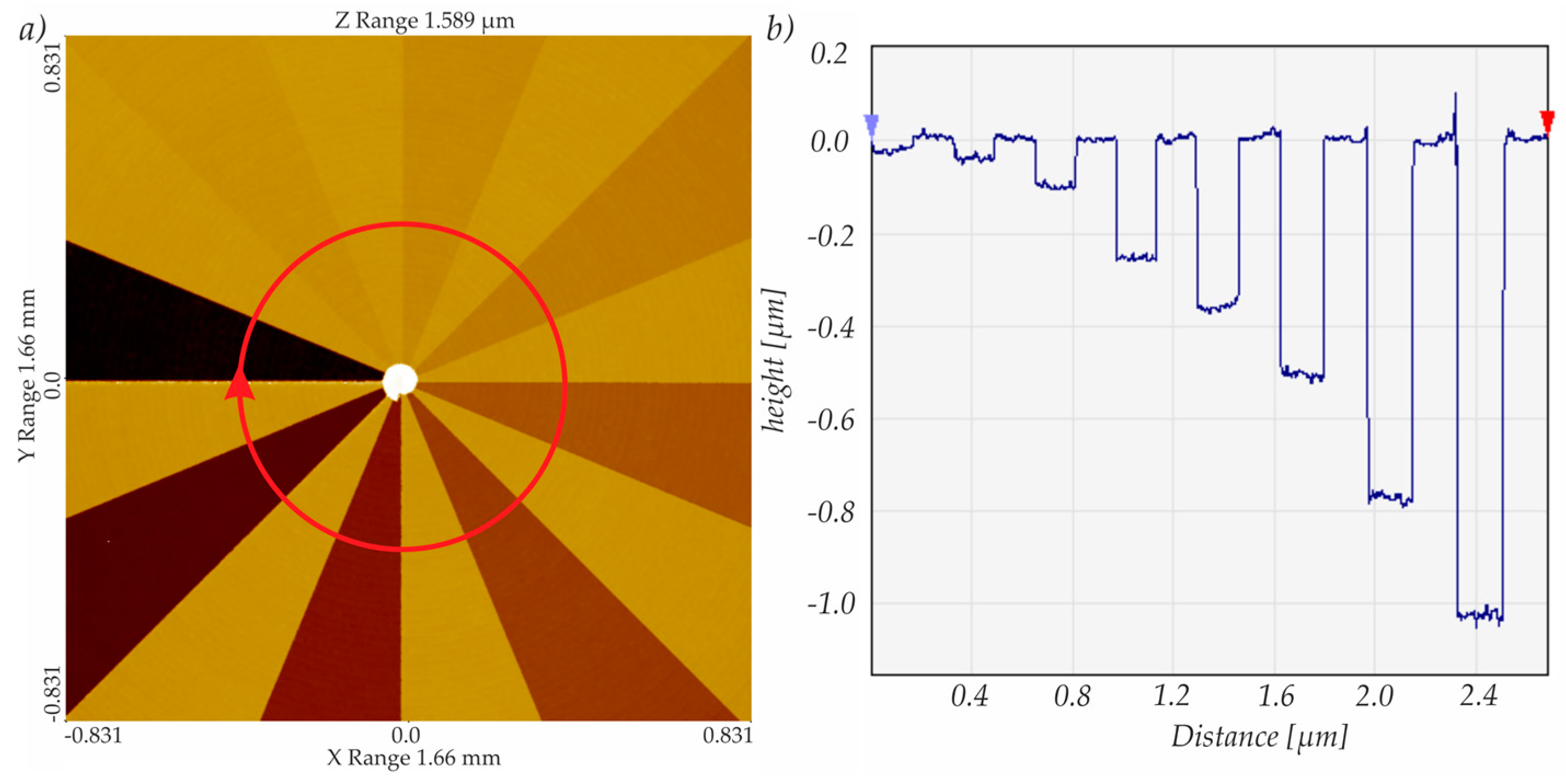
To determine the structure transition in the cutting direction, a defined alternation of the structure depth was carried out in the cutting direction, dependent on an angular position of the spindle (cf. Figure 6a). In this way, a Siemens star-like pattern with 16 sections was generated. Each measurement was repeated at different positions at the same area for statistical validation.
In the cutting direction, the structure transition angle was affected by the clearance angle for the entering tool movement, as well as by the dynamic of the nFTS for the retracting tool movement (Figure 7). The results presented in Figure 7 are measured at two different radii on the workpiece. In Figure 7a, the structure transition angle was measured at structures situated at an outer radius of the workpiece (radius approx. 8 mm), while the angles shown in Figure 7b were measured close to the workpiece center (radius approx. 2 mm). Comparing both graphics, a clear influence of the measurement area on the geometry of the retracting structure edge can be seen. While the transition angle at the inner radius is quite high (approximately 40–70°), the angle measured at the outer radius is significantly smaller (≈15°). This can be explained by the change in the cutting speed in the face turning process. Due to the combination of a constant rotational speed (100 rpm) and the outwardly increasing length of the cutting path per revolution at a spirally cutting trail, the cutting speed was high at the outer radius of the workpiece and decreased down to zero at the center. While the dynamic of the nFTS was high enough to generate a steep edge at low cutting speeds, at higher cutting speeds, it led to a slanted edge. Most of the measurements show a large spread. One reason for this is the choice of the measurement position. The transition angle is dependent on the radial position of the measurement position. Due to the limited measurement area of the WLI, it was not easy to choose exactly the same radius for each measurement, so this might vary to a limited extent.
Another aspect that can be seen in Figure 7 is the difference between the transition angles for depths of cut of 350 and 1000 nm. This can be explained by the lower control voltage used for the lower depth of cut, which leads to a lower speed for smaller distances.
The material impact on the structure angle is obvious in this case. Note that the structure angle in nickel silver is higher at all positions, but varies more.
3.3.2. Structure Transition in Feed Direction
In order to investigate the structure transition in the feed direction, the alternation was implemented at every fifth workpiece rotation (cf. Figure 8a). In this way, concentric circles are approximated. All experiments were conducted with both 10 and 20 μm diamond tools. Here again, the experimental results found with the 20 μm tool are presented.
The structure transition angle in the feed direction depends only on the tool geometry and the workpiece material as depicted in Figure 8c. Again, each measurement was repeated for statistical validation. The experiments show no visible impact of the material for this transition angle. The only difference can be observed in the fluctuation of the measurements. On average, the results conducted in nickel silver are more variable. This can be explained with the composition of the material consisting of grains of different sizes that tend to break out of the surface rather than be cut through. These unpredictable breakouts result in unequal transition angles.
The measured structure depth of these structures is described in Figure 9. For the measurement of the structure depth, measurements from all types of structures were evaluated by a white light interferometer. The results are shown in Figure 9. In this investigation, no impact of the material on the generated structure depth was determined. Since the structure depth is mainly affected by the positioning accuracy of the nFTS, which generates the depth of cut, this result was expected. In Figure 9b, the average measured structure depth against the nominal structure depth is shown for nickel silver and ultrafine-grained aluminum, which again shows no impact of the material.
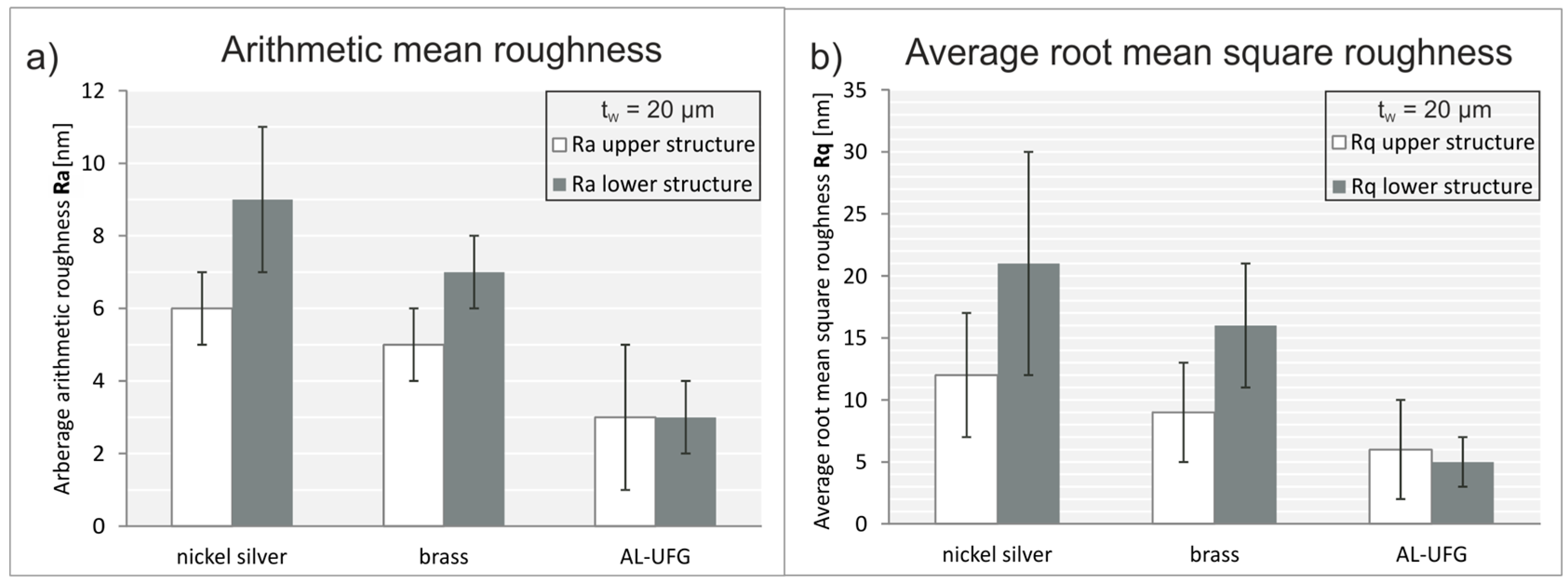
3.4. Impact of Materials on the Surface Roughness
The material impact on the surface finish is shown in Figure 10, for the arithmetic as well as the root mean square roughness. The measurements were conducted using all generated structure variations. The targeted optical quality of less than 10 nm Ra was achieved with all materials. Nevertheless, differences occur, most strikingly for nickel silver, which showed the highest surface roughness (Ra ≈ 9 nm and Rq ≈ 21 nm). The best surface finish was achieved for Al-UFG with an average arithmetic roughness of Ra = 3 nm and a quadratic roughness of Rq = 6 nm. This was expected, because of the small grain size and the low hardness of the aluminum, which leads to nearly isotropic grain properties.
Another phenomenon apparent in Figure 10 is the difference of the surface roughness for the upper and lower structure elements, where lower structure elements showed, in general, roughness values higher than those of the upper structure elements. This effect is only detected for nickel silver and brass, but in both roughness parameters. This suggests an impact of the structure depth on the surface roughness, which can be explained by the higher amount of removed material as well as the higher cutting forces that accompany the higher depth of cut.
The presented results were obtained from experiments conducted with a 20 μm diamond tool, though the experiments with the 10 μm tool showed comparable results.
4. Conclusions
The structuring quality in a diamond machining process for the machining of diffractive optical elements is presented, depending on different machining parameters, with special attention on the material impact on the structure quality. It has been confirmed that the choice of the feed depending on the tool width always has an impact on the structure width, which suggests that, for increasing the structuring accuracy with regard to the structure width, a measurement technology with higher resolution is recommended. The uniformity of the structure width was slightly worse in Al-UFG compared to the other materials, which can be explained by the mechanical properties of the material. Due to this, burr formation occasionally occurred, which might have reduced the optical performance of the resulting structure. Regarding the structure depth, only the stroke and the dynamic behavior of the nFTS can be regarded as decisive factors. With respect to the transition angle in the cutting direction, the clearance angle and the dynamic behavior of the nFTS were shown to have the greatest impact, while the best results, as expected, were obtained in nickel silver. In contrast, no material impact concerning the transition angle in the feed direction was found. With regard to surface roughness, the best results were achieved with the machining of Al-UFG, showing a surface finish in optical quality for all machined structures, independent of the depth of the cut. This leads to the final conclusion that the choice of material always has to be made in consideration of the specific application. Nickel silver is recommended for mold machining, due to its accurate structuring geometry and the durability of the mold. However, if the workpiece is used optically in reflecting applications, a high surface finish is the most important feature. Thus, ultrafine-grained aluminum might be a better choice.
Acknowledgments
The authors would like to thank the German Research Foundation (DFG) for funding this project (BR 825/77-1) and the colleagues from Bremer Institut für angewandte Strahltechnik (BIAS) for accomplishing the optical design.
Author Contributions
Ann-Katrin Holthusen designed and performed the experiments, and analyzed the data. Ann-Katrin Holthusen wrote the manuscript with support from Oltmann Riemer. Oltmann Riemer and Ekkard Brinksmeier supervised the project and conceived the original idea.
Conflicts of Interest
The authors declare no conflict of interest. The founding sponsors had no role in the design of the study; in the collection, analyses, or interpretation of data; in the writing of the manuscript; or in the decision to publish the results.
References
- Brunner, R. Transferring diffractive optics from research to commercial applications: Part II—Size estimation for selected markets. Adv. Opt. Technol. 2014, 3, 121–128. [Google Scholar] [CrossRef]
- Fang, F.Z.; Zhang, X.D.; Weckenmann, A.; Zhang, G.X.; Evans, C. Manufacturing and measurement of freeform optics. CIRP Ann. 2013, 62, 823–846. [Google Scholar] [CrossRef]
- Huang, R.; Zhang, X.; Rahman, M.; Kumar, A.S.; Liu, K. Ultra-precision machining of radial Fresnel lens on roller moulds. CIRP Ann. 2015, 64, 121–124. [Google Scholar] [CrossRef]
- Brinksmeier, E.; Riemer, O.; Gläbe, R.; Lünemann, B.; von Kopylow, C.; Dankwart, C.; Meier, A. Submicron functional surfaces generated by diamond machining. CIRP Ann. 2010, 59, 535–538. [Google Scholar] [CrossRef]
- Meier, A. Diamond turning of diffractive microstructures. Precis. Eng. 2015, 42, 253–260. [Google Scholar] [CrossRef]
- Dankwart, C.; Falldorf, C.; Bergmann, R.B. Design of Diamond turned holograms for multiple wavelength image formation. In Proceedings of the 12th Workshop on Information Optics (WIO), Puerto de la Cruz, Spain, 15–19 July 2013. [Google Scholar]
- Paul, E.; Evans, C.J.; Mangamelli, A.; McGlauflin, M.L.; Polvani, R.S. Chemical aspects of tool wear in single point diamond turning. Precis. Eng. 1996, 18, 4–19. [Google Scholar] [CrossRef]
- Bliedtner, J.; Gräfe, G. Optiktechnologie—Grundlagen, Verfahren, Anwendungen, Beispiele, 2nd ed.; Carl Hanser Verlag: Munich, Germany, 2010. [Google Scholar]
- Furushiro, N.; Tanaka, H.; Higuchi, M.; Yamaguchi, T.; Shimada, S. Suppression mechanism of tool wear by phosphorous addition in diamond turning of electroless nickel deposits. CIRP Ann. 2010, 59, 105–108. [Google Scholar] [CrossRef]
- To, S.; Lee, W.B. Deformation behaviour of aluminium single crystals in ultraprecision diamond turning. J. Mater. Process. Technol. 2001, 113, 296–300. [Google Scholar] [CrossRef]
- Tauhiduzzaman, M.; Veldhuis, S.C. Effect of material microstructure and tool geometry on surface generation in single point diamond turning. Precis. Eng. 2014, 38, 481–491. [Google Scholar] [CrossRef]
- Davies, M.A.; Dutterer, B.S.; Suleski, T.J.; Silny, J.F.; Kim, E.D. Diamond machining of diffraction gratings for imaging spectrometers. Precis. Eng. 2012, 36, 334–338. [Google Scholar] [CrossRef]
- Preuß, W. Chemisch Nickel in der Optik. Tagungsband der DGO-Tagung Einsatzerfahrungen und Anwendungen von Nickel- und Nickellegierungsüberzügen, Düsseldorf, Germany, 14–15 November 1995; pp. 42–46. [Google Scholar]
- Brecher, C.; Baum, C.; Meiers, B.; De Simone, D.; Krappig, R. Kunststoffkomponenten für LED-Beleuchtungsanwendungen; Springer Vieweg: Aachen, Germany, 2016. [Google Scholar]
- Meier, A. Diamantdrehen Komplexer Diffraktiver Mikrostrukturen; Shaker-Verlag: Bremen, Germany, 2016. [Google Scholar]
- Brinksmeier, E.; Riemer, O.; Gläbe, R.; Meier, A. Material aspects for the diamond machining of submicron optical structures for UV-application. Int. J. Nanomanuf. 2011, 7, 63–72. [Google Scholar] [CrossRef]
Figure 1.
Process principle for diamond machining of holograms with varying structure angles.
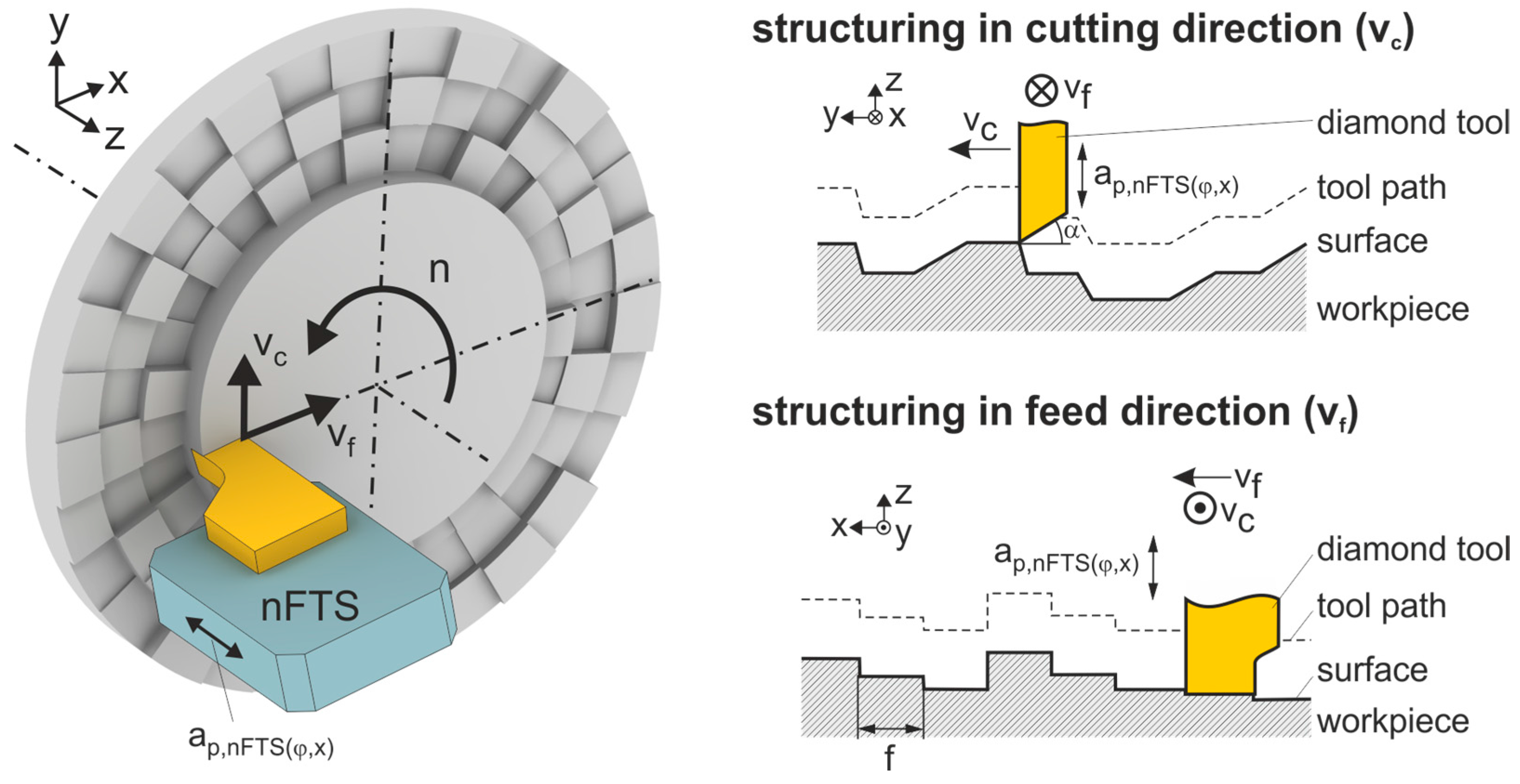
Figure 2.
Nanotech 350 FG ultra precision turning lathe and experimental setup.
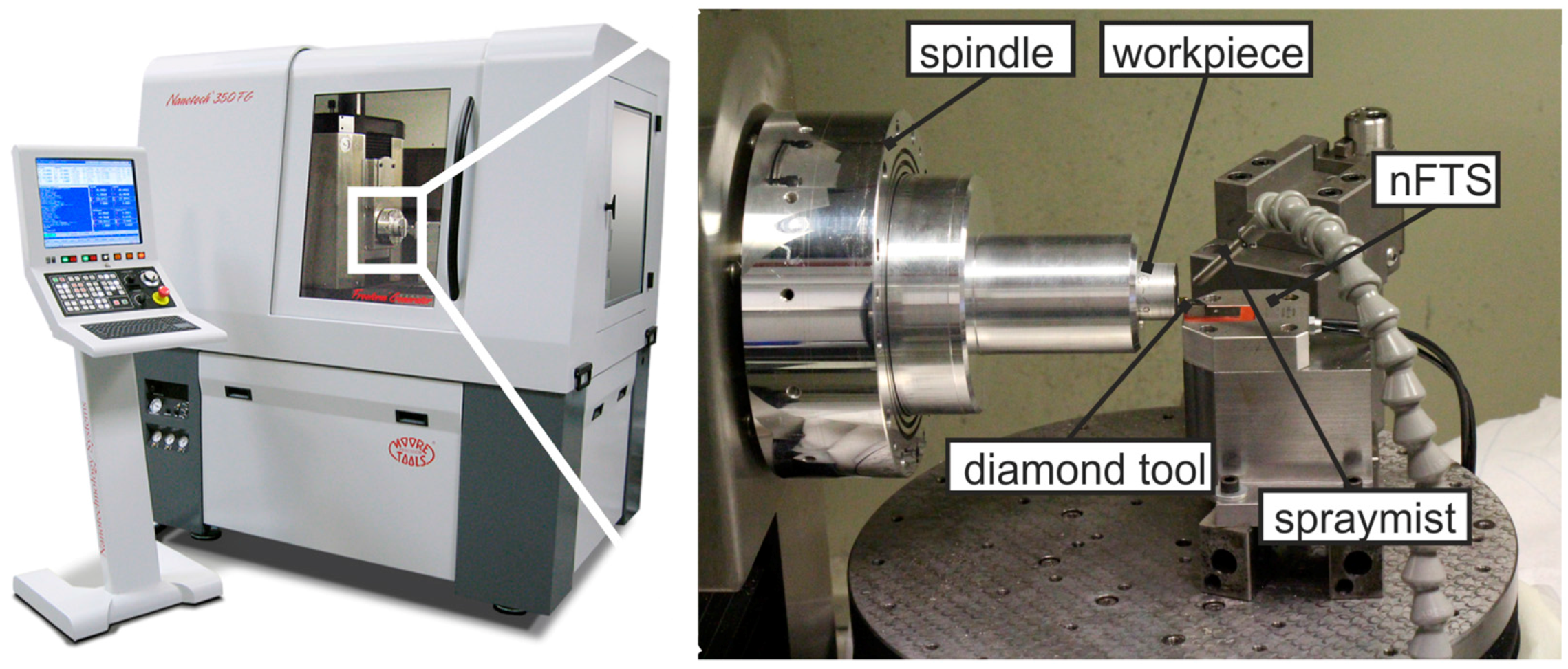
Figure 3.
(a) Measurement of the diamond tool with a light microscope (magnification 1000×); (b) measurement of the tool tip with an atomic force microscope; (c) cross section of the tool tip measurement with evaluation of the cutting edge radius.
Figure 3.
(a) Measurement of the diamond tool with a light microscope (magnification 1000×); (b) measurement of the tool tip with an atomic force microscope; (c) cross section of the tool tip measurement with evaluation of the cutting edge radius.
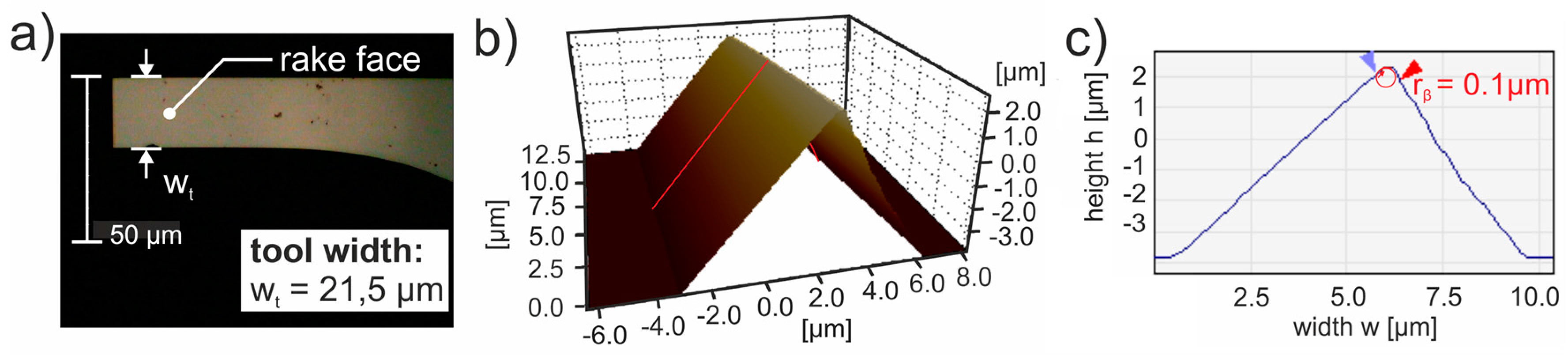
Figure 4.
Influence of the material on the structure width (a) with a feed of f = 21.0 μm and (b) with a feed of f = 21.5μm.
Figure 4.
Influence of the material on the structure width (a) with a feed of f = 21.0 μm and (b) with a feed of f = 21.5μm.
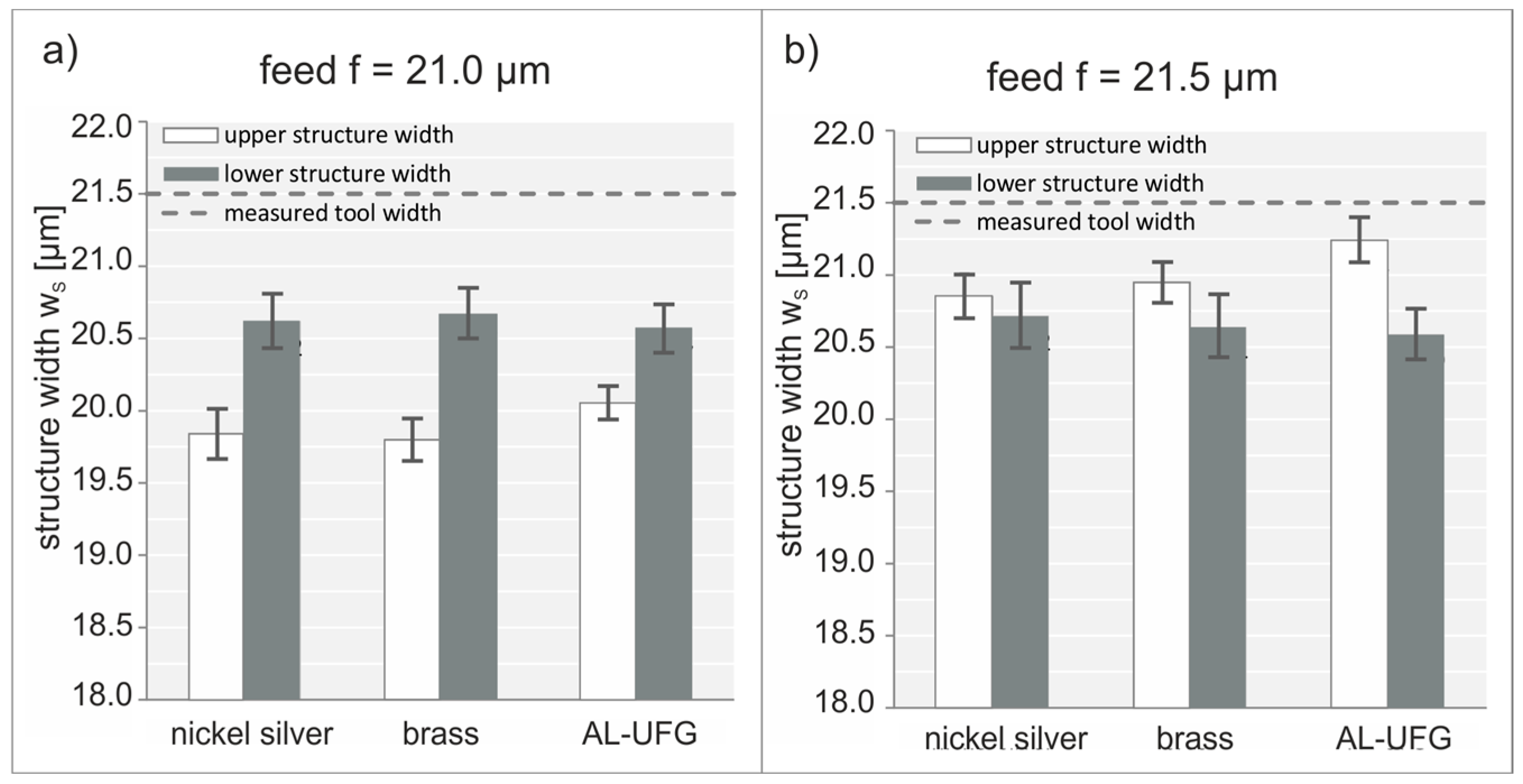
Figure 5.
Structure width depending on the feed.
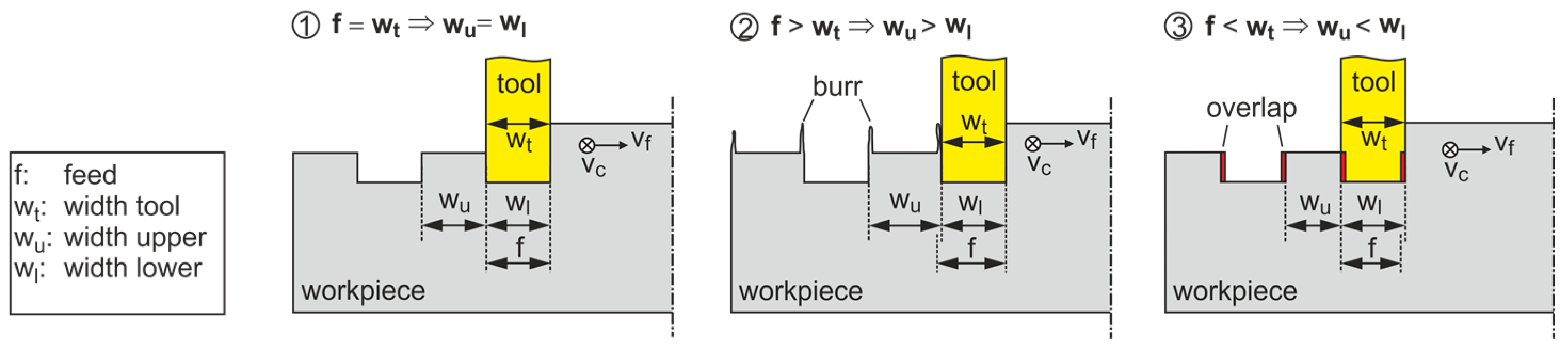
Figure 6.
(a) Light interferometric measurement of the structure transition in the cutting direction and (b) a circular cross section.
Figure 6.
(a) Light interferometric measurement of the structure transition in the cutting direction and (b) a circular cross section.

Figure 7.
Structure transition angle in the cutting direction measured for all materials at (a) the outer radius of the workpiece and (b) the inner radius of the workpiece.
Figure 7.
Structure transition angle in the cutting direction measured for all materials at (a) the outer radius of the workpiece and (b) the inner radius of the workpiece.
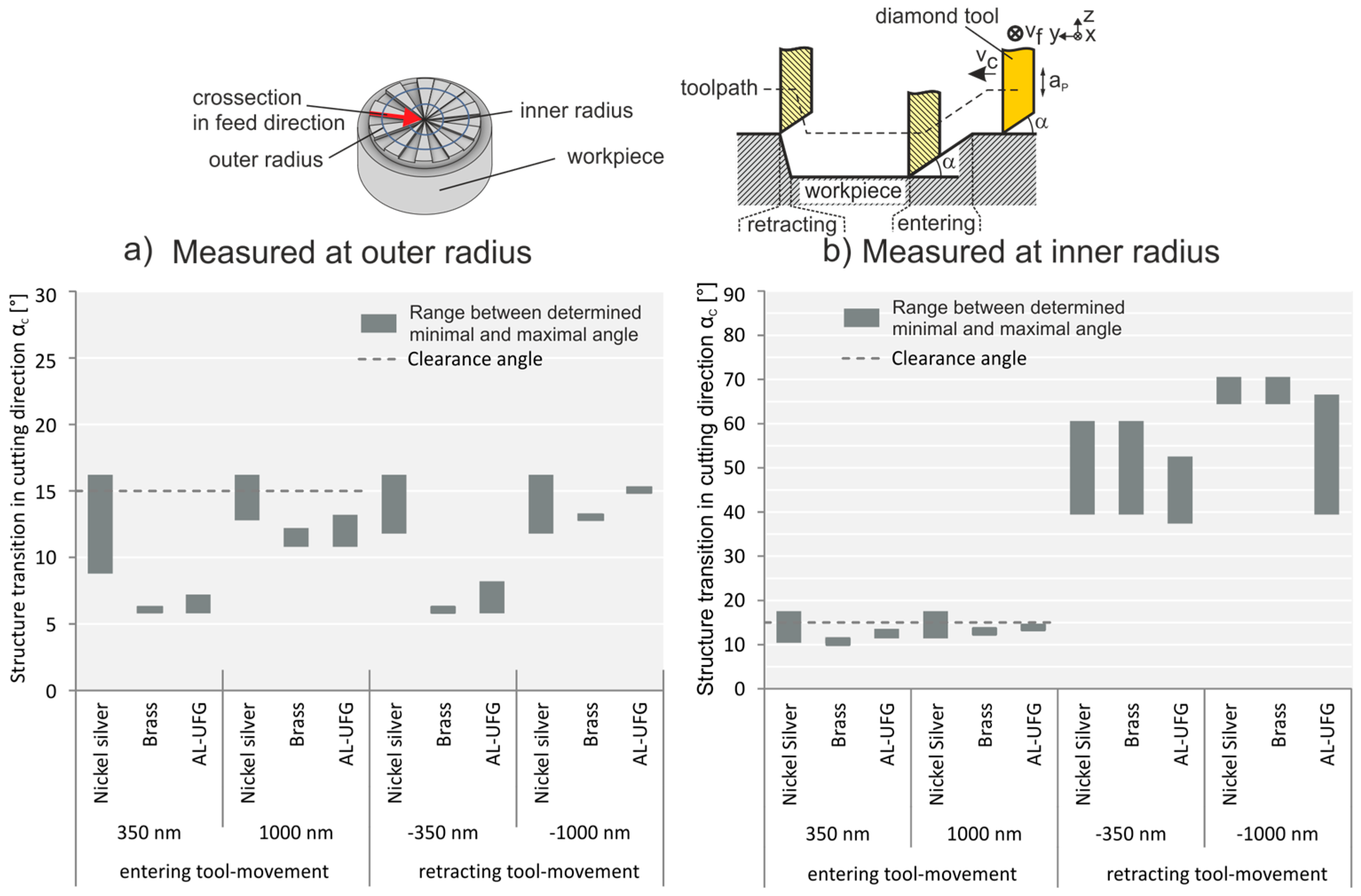
Figure 8.
(a) With light interferometric measurement of the structure transition in the feed direction, (b) a linear cross section, and (c) the structure transition angle in the feed direction.
Figure 8.
(a) With light interferometric measurement of the structure transition in the feed direction, (b) a linear cross section, and (c) the structure transition angle in the feed direction.
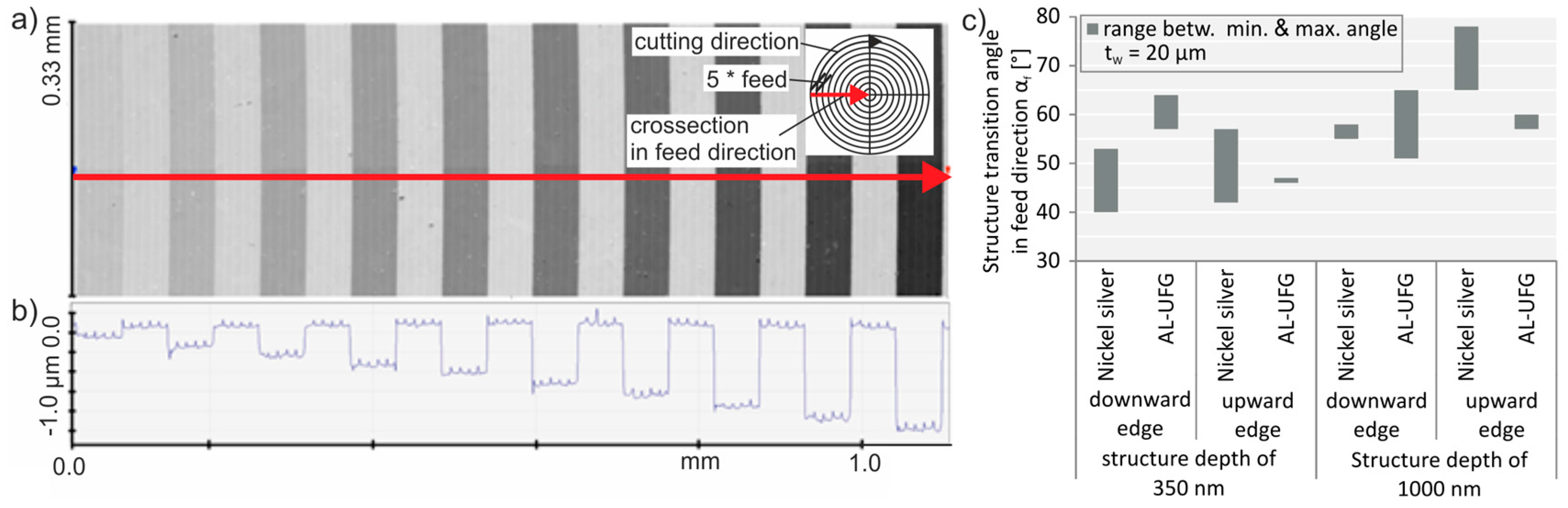
Figure 9.
(a) Measured structure depth and (b) average deviation of the measured structure depth with respect to the nominal structure depth.
Figure 9.
(a) Measured structure depth and (b) average deviation of the measured structure depth with respect to the nominal structure depth.

Figure 10.
Material impact on the surface roughness: (a) arithmetic roughness and (b) root mean squared roughness.
Figure 10.
Material impact on the surface roughness: (a) arithmetic roughness and (b) root mean squared roughness.


Table 1.
Tool characteristics.
| Material | Monocrystalline Diamond |
|---|---|
| Clearance angle α | 20° |
| Rake angle γ | 0° |
| Tool width tw | 11.7 μm; 21.5 μm |
| Cutting edge radius rβ | 0.1 μm |
Table 2.
Mechanical properties of the investigated materials.
| Material | Average Grain Size (dg) [μm] | Density (ρ) [gcm−3] | Hardness (HV) [HV0.05] | Elastic Modules (E) [kN/mm2] | Tensile Strength (Rm) [N/mm2] |
|---|---|---|---|---|---|
| Al-UFG | ≈0.4 | n.a. | 51 | n.a. | 203 |
| brass: CuNi7Zn39Pb3Mn2 | 8–44 | 8.44 | 143 | 120 | 470 |
| nickel silver: CuZn39Pb3 | n.a. | 8.46 | 90–175 HB | 96 | 340–600 |
Table 3.
Material impact on the structure geometry.
| WLI | Profile | |
| Nickel Silver |  |  |
| Brass |  |  |
| Al-UFG |  | burr formation |
© 2018 by the authors. Licensee MDPI, Basel, Switzerland. This article is an open access article distributed under the terms and conditions of the Creative Commons Attribution (CC BY) license (http://creativecommons.org/licenses/by/4.0/).
Share and Cite
MDPI and ACS Style
Holthusen, A.-K.; Riemer, O.; Brinksmeier, E. Material Impact on Diamond Machining of Diffractive Optical Structures for UV-Application. J. Manuf. Mater. Process. 2018, 2, 15. https://doi.org/10.3390/jmmp2010015
AMA Style
Holthusen A-K, Riemer O, Brinksmeier E. Material Impact on Diamond Machining of Diffractive Optical Structures for UV-Application. Journal of Manufacturing and Materials Processing. 2018; 2(1):15. https://doi.org/10.3390/jmmp2010015
Chicago/Turabian StyleHolthusen, Ann-Katrin, Oltmann Riemer, and Ekkard Brinksmeier. 2018. "Material Impact on Diamond Machining of Diffractive Optical Structures for UV-Application" Journal of Manufacturing and Materials Processing 2, no. 1: 15. https://doi.org/10.3390/jmmp2010015