Study on Electrolytic Magnetic Abrasive Finishing for Finishing Stainless Steel SUS304 Plane with a Special Compound Machining Tool


Graduate School of Engineering, Utsunomiya University, 7-1-2 Yoto, Utsunomiya, Tochigi 321-8585, Japan
*
Author to whom correspondence should be addressed.
J. Manuf. Mater. Process. 2018, 2(3), 41; https://doi.org/10.3390/jmmp2030041
Submission received: 25 April 2018
/
Revised: 17 June 2018
/
Accepted: 19 June 2018
/
Published: 26 June 2018
Abstract
:In order to improve the finishing efficiency of traditional plane magnetic abrasive finishing (MAF), we have previously proposed an effective plane MAF process combined with an electrolytic process and developed a special compound machining tool for the electrolytic magnetic abrasive finishing (EMAF). In this research, the EMAF process is divided into two finishing steps. The first finishing step is the EMAF step, and a single MAF step constitutes the second finishing step. The machinability of SUS304 material can be improved through the formation of passive films from the electrolytic process in the EMAF step. Meanwhile, the passive films can be rapidly and easily removed by friction between the magnetic particles and the workpiece-generated mechanical machining force. Thus, the surface finishing efficiency can be greatly improved. Compared with a dedicated MAF machining tool or a dedicated electrolytic machining tool, this special compound machining tool can synchronously achieve MAF and electrolytic processes to make the processing more convenient. This study focuses on exploring mechanical finishing characteristics of the special compound machining tool through MAF experiments. Additionally, EMAF experiments are conducted under the optimal mechanical finishing conditions. The experimental results of the EMAF process show that the surface roughness Ra can be reduced to less than 30 nm at the 4-min EMAF step, and it can be further reduced to 20 nm at the 10-min MAF step.
1. Introduction
With the development of semiconductor-related and biotechnology-related industries, the demands for surface quality and machining efficiency are becoming higher and higher. Therefore, the finishing operation is more and more important in the whole production process. Among the many precision machining methods, magnetic abrasive finishing (MAF) is undoubtedly proven to be an effective precision processing method [1,2,3,4]. Though the MAF process, as a kind of ultra-precision machining method, can achieve nanoscale surface finishing, the polishing efficiency decreases when a hard metal surface is polished by the MAF process, as compared to other processing methods [5,6,7]. Thereby, diamond is usually used to polish hard metal surfaces in the MAF process in order to ensure the polishing efficiency. As a result, the polishing costs become high. In recent years, in order to improve surface accuracy and polishing efficiency, researchers have not only optimized and improved the parameters of magnetic abrasive finishing, but also dedicated efforts to explore magnetic abrasive finishing combined with a variety of processes. In these MAF compound processing methods, electrolytic/electrochemical magnetic abrasive finishing (EMAF) has been proposed and conducted by a few researchers. Among them, Zou et al. developed magnetic abrasive finishing combined with electrolytic process methods to respectively polish the plane workpiece and internal surface of a tube. A large number of experimental results have indicated that the polishing efficiency of a metal material can be significantly improved through magnetic abrasive finishing combined with the electrolytic process [8,9]. Pandey et al. also proved that chemo-ultrasonic assisted magnetic abrasive finishing is effective through a series of experimental investigations, and a regression model was developed to predict the percentage change in surface roughness in terms of significant processing factors [10]. Yadava et al. investigated the effect of electrolytic current, magnetic flux density, and the rotational speed of workpiece on material removal and surface roughness through electrochemical dissolution and magnetic abrasive machining [11]. Based on the abovementioned reports, it can be considered that the finishing efficiency of a metal material can be improved by the EMAF process.
Currently, the EMAF method is usually divided into synchronous finishing and steps finishing. The synchronous EMAF process is realized by a special compound machining tool [12]; the steps EMAF process involves passive films being formed on the workpiece surface by an oxidizing agent before the experiment, after which they are removed by a dedicated magnetic machining tool [13]. However, the development of EMAF process compound machining tools is very scarce. Hence, a special compound machining tool was developed before this study. The MAF and electrolytic processes are two important finishing parts of the EMAF process. The electrolytic process takes a primary role in removing material and reducing the surface hardness of a workpiece for the EMAF process [14,15,16,17]. Generally, the roughness of the metal surface can be minimized in a shorter finishing time by the electrolytic process. However, the mirror polishing is difficult to be achieved by only the electrolytic process due to the generation of passive films on the surface. The synchronous MAF process is used to remove the generated passive films from the electrolytic process in order to achieve precision machining. The MAF and electrolytic processes are synchronously performed in the first finishing step, then the MAF process as a final process continues to be performed in the second finishing step in order to obtain a perfect surface profile accuracy with a high machining efficiency.
In this study, we focused on exploring the mechanical finishing characteristics of the special compound machining tool through MAF experiments. Additionally, EMAF experiments were conducted under the optimal mechanical finishing conditions. The experimental results of EMAF process demonstrated that the efficiency of precision machining can be significantly improved.
2. Processing Principles
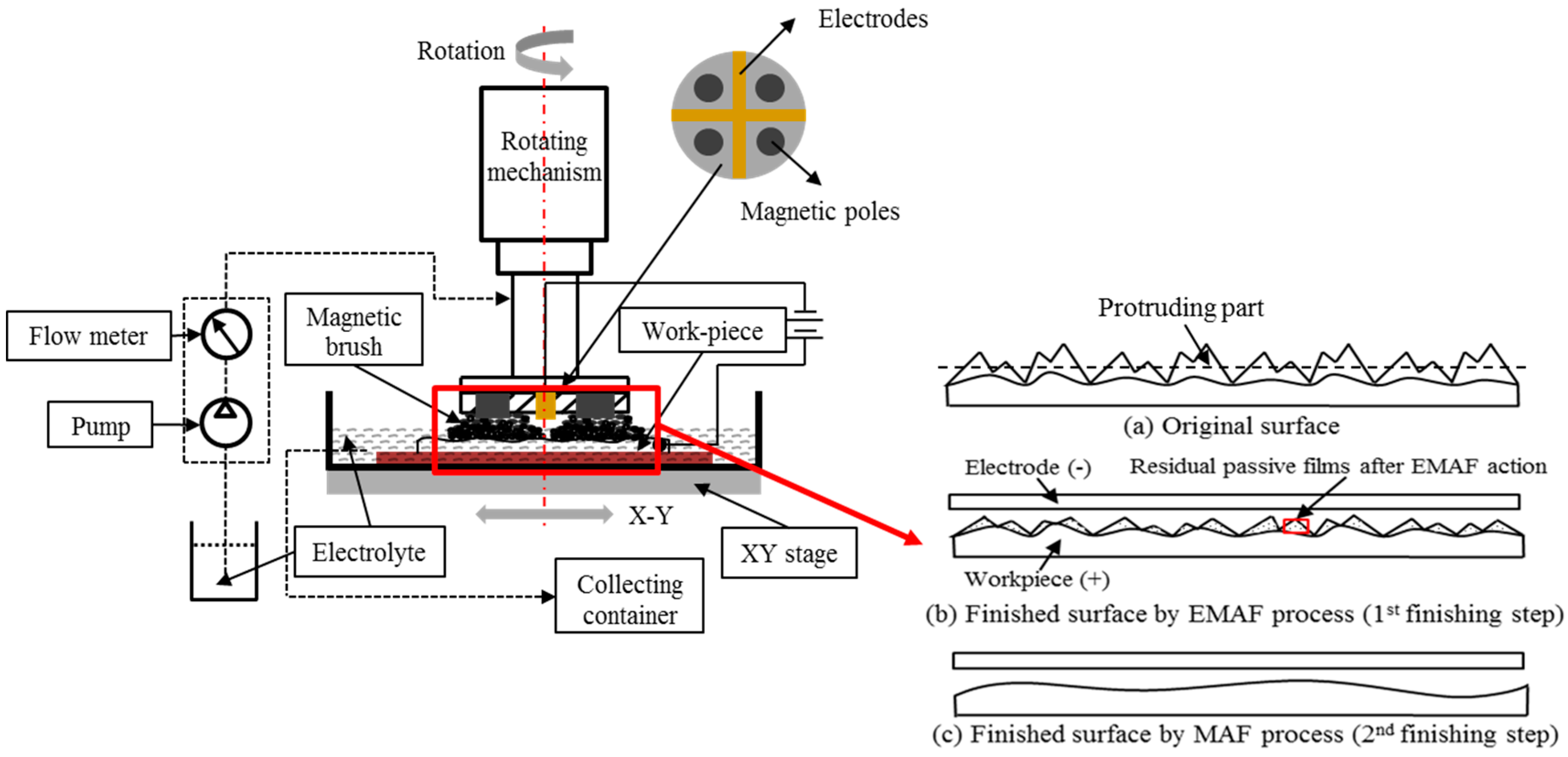
In this research, the EMAF process includes two finishing steps, which are respectively the first finishing step (EMAF step) and the second finishing step (MAF step). The machining principle of the EMAF process is shown in Figure 1. Figure 1a shows the original surface with a lot of initial hairlines before finishing. Figure 1b shows the finished surface after the EMAF step. When turning on DC constant voltage power, the protruding portions are preferentially leveled and passive films are formed on the workpiece surface by the electrolytic process. Simultaneously, the magnetic abrasive particles of a magnetic brush are used to exert friction on the workpiece surface so the passive films can be effectively removed. Also, the hardness of the passive films is smaller than the hardness of SUS304 stainless material [18]. Thus, the efficiency of precision machining can be improved through the first finishing step—the EMAF process. However, a few passive films still exist on the finished surface after the EMAF step. The residual passive films affect the surface accuracy. Hence, the MAF step represents a final process after the EMAF step that is used to completely remove all passive films in order to improve the surface accuracy of the workpiece. Figure 2c shows the finished surface after the MAF step.
3. Experimental Setup
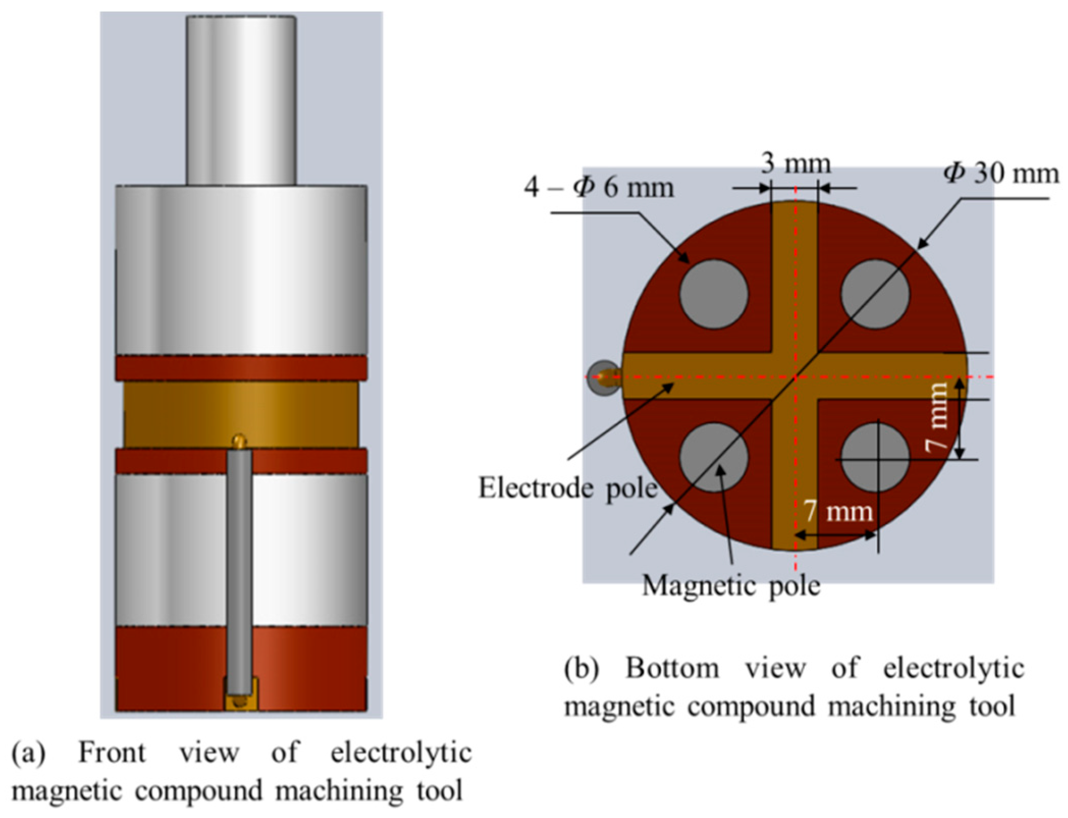
The three-dimensional views of the electrolytic magnetic compound machining tool are shown in Figure 2. In order to be able to synchronously achieve the MAF and electrolytic processes, four magnetic poles (Φ6 mm) and a cross-shape cathode (30 × 3 × 3 mm) are embedded in the bottom of the electrolytic magnetic compound machining tool. The electrode connects to a copper ring with a wire. The current flows from the negative pole of the DC power source to the electrode of the compound machining tool through the carbon brush connected to the copper ring. Additionally, the magnetic brush forms at the magnetic poles.
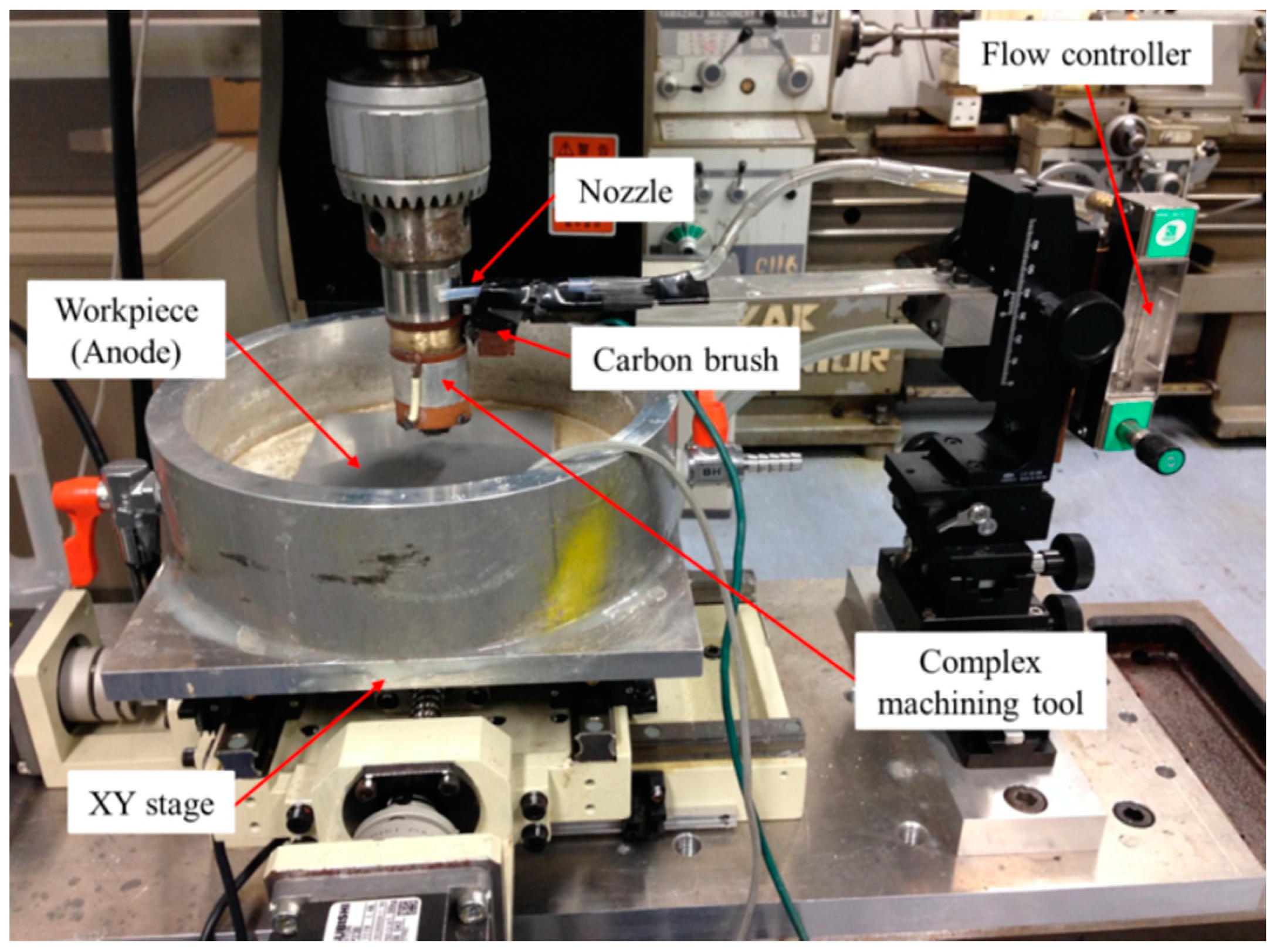
Figure 3 shows the experimental setup of electrolytic magnetic abrasive finishing. The workpiece is a SUS304 plane that is 100 mm in length, 100 mm in width, and 1 mm in thickness. The electrolytic magnetic compound machining tool is fixed on the chuck of a milling machine. The rotational direction and velocity of the compound machining tool are controlled by the milling machine. The SUS304 plane workpiece as an anode is fixed in the container and connected to the positive pole of the DC power source. The NaNO3 electrolyte solution is supplied from a nozzle by a pump, and the flow rate of the electrolyte is controlled through a flow meter. The workpiece and container are laid on the X-Y stage. The feeding trajectory and velocity of the X-Y stage are controlled by a numerical control (NC) program system.
4. Experimental Results and Discussion
4.1. Experimental Procedure and Conditions of the MAF Process
The MAF process as an important finishing part of the EMAF process, as the mechanical finishing characteristics of the electrolytic magnetic compound machining tool first need to be explored by the MAF process experiments. Therefore, we focused on investigating the mixed magnetic abrasive, rotational speed of the machining tool and the working gap. The detailed experimental conditions of the MAF process are shown in Table 1. The original surface roughness Ra of the workpiece is measured to be approximately 0.16~0.2 μm. The mixed magnetic abrasive respectively consists of quantitative electrolytic iron powder with 330 μm, 149 μm, 75 μm in mean diameter and quantitative #4000, #6000, #8000, #10000 WA particles. In order to ensure that the machining power is adequate, the working gap is respectively adjusted to 1 mm and 2 mm. To obtain a higher surface accuracy and higher machining efficiency, the rotational speed of the machining tool is respectively selected at 230 rpm and 450 rpm. The finishing time of the MAF process is limited at 60 min. After each finishing step, the finished surface is measured and observed by a contact roughness meter (Mitutoyo, in 1-20-1 Sakado, Takatsu, Kawasaki, Japan) and three-dimensional (3D) non-contact optical profiling microscopy (Wyko-Vision NT1100, in 1-1-30 Shibadaimon, Minato, Tokyo, Japan) at these three locations, as shown in Figure 4.
4.2. Experimental Results of the MAF Process
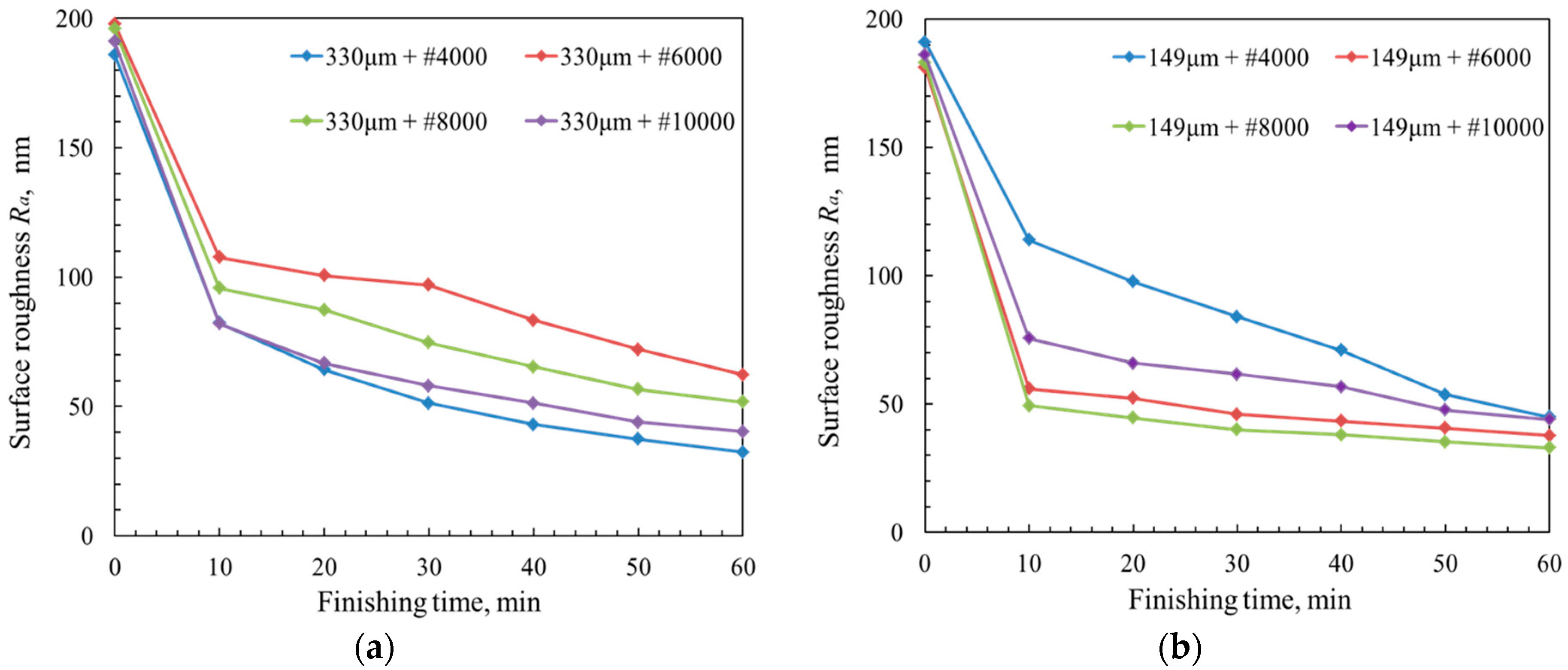
Figure 5a–c respectively shows the change in surface roughness Ra under the conditions of the iron powder with mean diameters of 330 μm, 149 μm, 75 μm mixed with different sizes of WA particles. Through respectively comparing the experimental results in Figure 5a–c, it can be seen that the optimal surface roughness can be obtained under the conditions of 330-μm iron powder mixed with #4000 WA particles, 149-μm iron powder mixed with #8000 WA particles, and 75-μm iron powder mixed with #10000 WA particles. Then, the best experimental results under different diameters of iron powder conditions were compared, as shown in Figure 5d. The combination of 149-μm iron powder mixed with #8000 WA particles can be considered as the optimal mixed magnetic abrasive by comparing the best experimental results shown in Figure 5d.
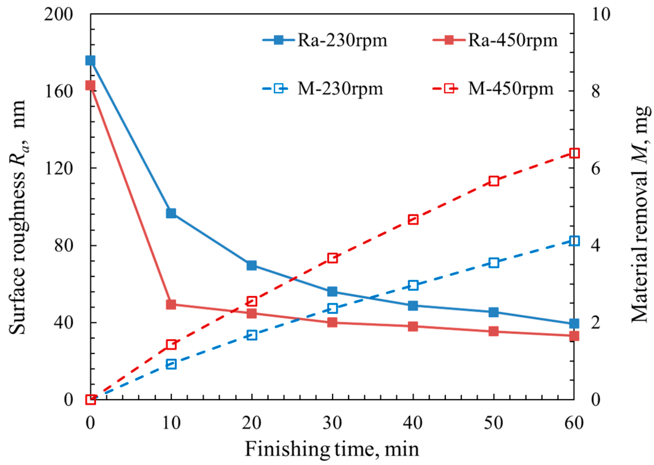
Figure 6 shows the effects of the machining tool’s different rotational speeds on the change in surface roughness Ra and material removal M in the 60-min MAF process. It can be seen that the surface roughness Ra at 450 rpm rotational speed was obviously smaller than the surface roughness Ra at 230 rpm rotational speed in the 60-min MAF process. In addition, the material removal M at 450 rpm rotational speed was also much more than the material removal M at 230 rpm rotational speed.
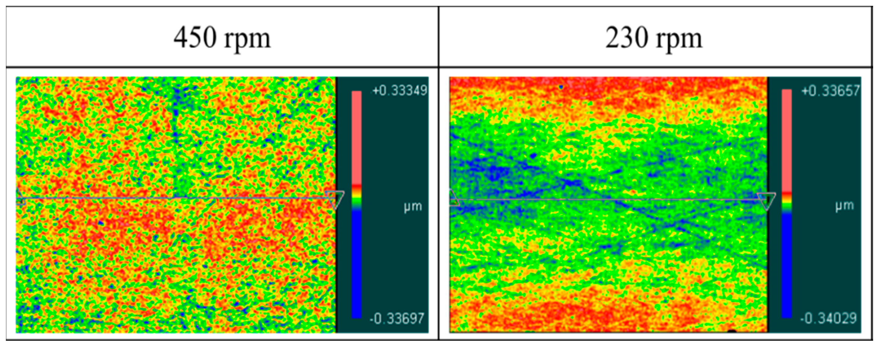
The macroscopic confocal images of the finished surface at the 60-min MAF process under the conditions of various rotational speeds of the machining tool are shown in Figure 7. It can be clearly seen that the color distribution of the finished surface was mainly green, yellow, and red at 450 rpm rotational speed, while it was mainly green, yellow, red, and blue at 230 rpm rotational speed. Thus, it was regarded that the finished surface accuracy at 450 rpm rotational speed was slightly better than the finished surface accuracy at 230 rpm rotational speed. Moreover, it can be clearly seen that the initial hairlines of the workpiece surface have almost completely been removed at both 450 rpm and 230 rpm rotational speed conditions. However, a few scratched hairlines remained on the finished surface in the 230 rpm rotational speed case. Thus, it can be recognized that a higher surface accuracy can be obtained at relatively higher rotational speed conditions.
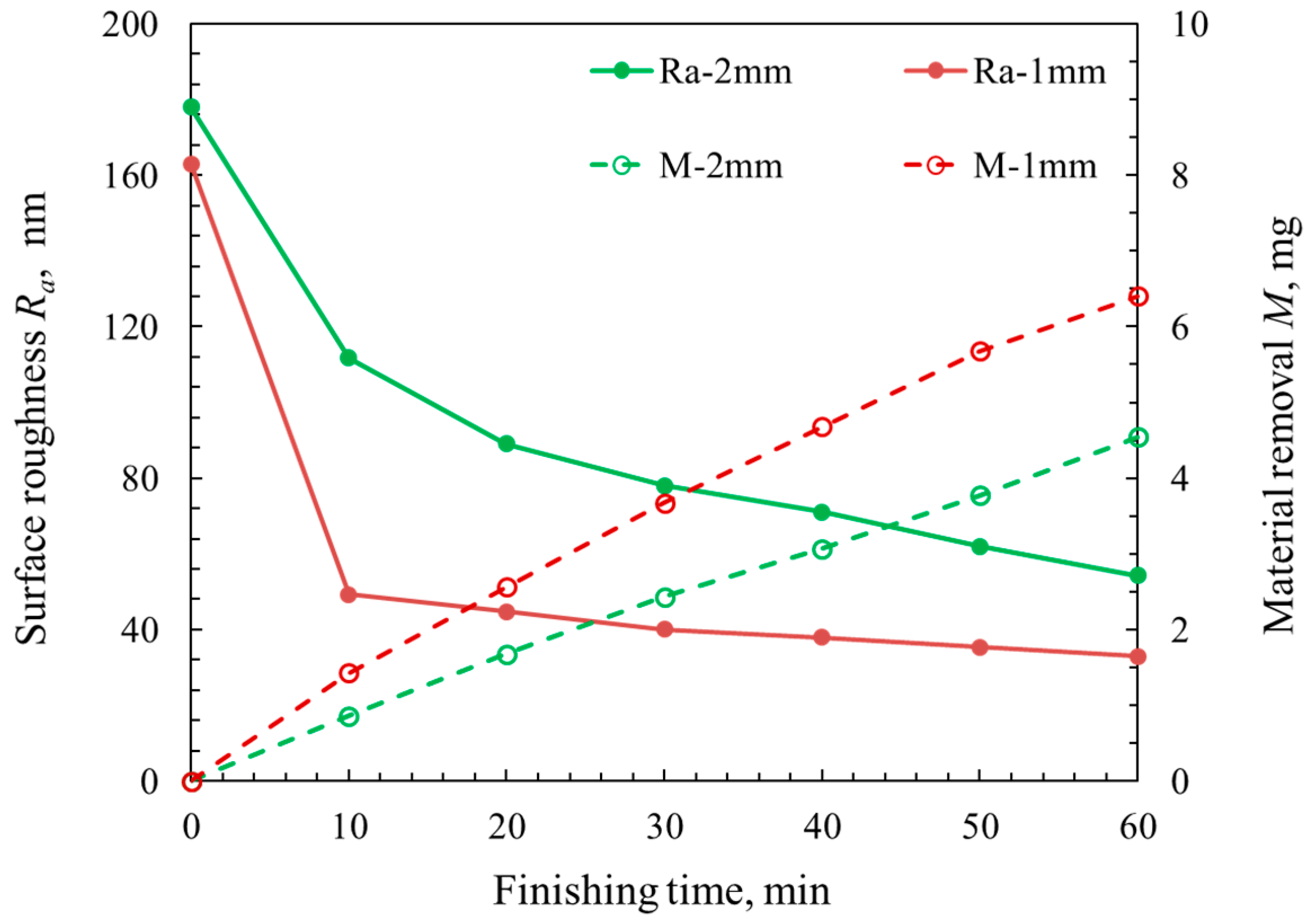
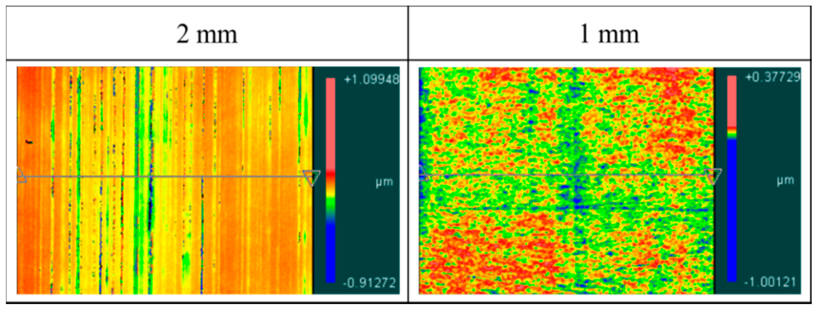
Figure 8 shows the change in surface roughness Ra and material removal M under various working gaps. It was recognized that the surface roughness Ra under a 1-mm working gap was remarkably smaller than the surface roughness Ra under a 2-mm working gap in the 60-min MAF process. Furthermore, the material removal M under the 1-mm working gap was also much more than the material removal M under the 2-mm working gap.
The macroscopic confocal images of the finished surface after the 60-min MAF process under the conditions of different working gaps are shown in Figure 9. Through comparing the finished surface profile after the 60-min MAF process under the conditions of different working gaps, it was recognized that the finished surface accuracy at a 1-mm working gap was obviously better than the finished surface accuracy at a 2-mm working gap. Furthermore, it can be clearly seen that the initial hairlines of the finished surface were almost completely removed in the 1-mm working gap case. However, many initial hairlines still existed on the finished surface in the 2-mm working gap case. Thus, it can be recognized that a higher surface accuracy can be obtained at relatively smaller working gap conditions.
4.3. Experimental Procedure and Conditions of the EMAF Process
According to the investigated mechanical machining characteristics of the compound machining tool, it can be regarded that the effect of the rotational speed and working gap on the mechanical machining characteristics are very obvious in the MAF process. Based on the experimental results of the MAF process, the detailed experimental conditions of the EMAF process were decided and are shown in Table 2. The original surface roughness Ra of the workpiece is measured to be approximately 0.16~0.2 μm. The mixed magnetic abrasive consists of quantitative electrolytic iron powder with a mean diameter of 149 μm and quantitative #8000 WA particles. The working gap is adjusted to 1 mm, the rotational speed of compound machining tool is selected at 450 rpm, and the feeding speed of the X-Y stage is adjusted to 5 mm/s. The working voltage is selected to be 12 V. The electrolyte concentration is selected as 20 wt % NaNO3 electrolyte solution. The total finishing time of the EMAF process is limited to 30 min. This total finishing time is a combination of the 4-min EMAF step and 26-min MAF step. The finished surface is respectively measured and observed after the 4-min EMAF step, each 10-min MAF step, and the remaining 6-min MAF step.
4.4. Experimental Results and Discussions of the EMAF Process
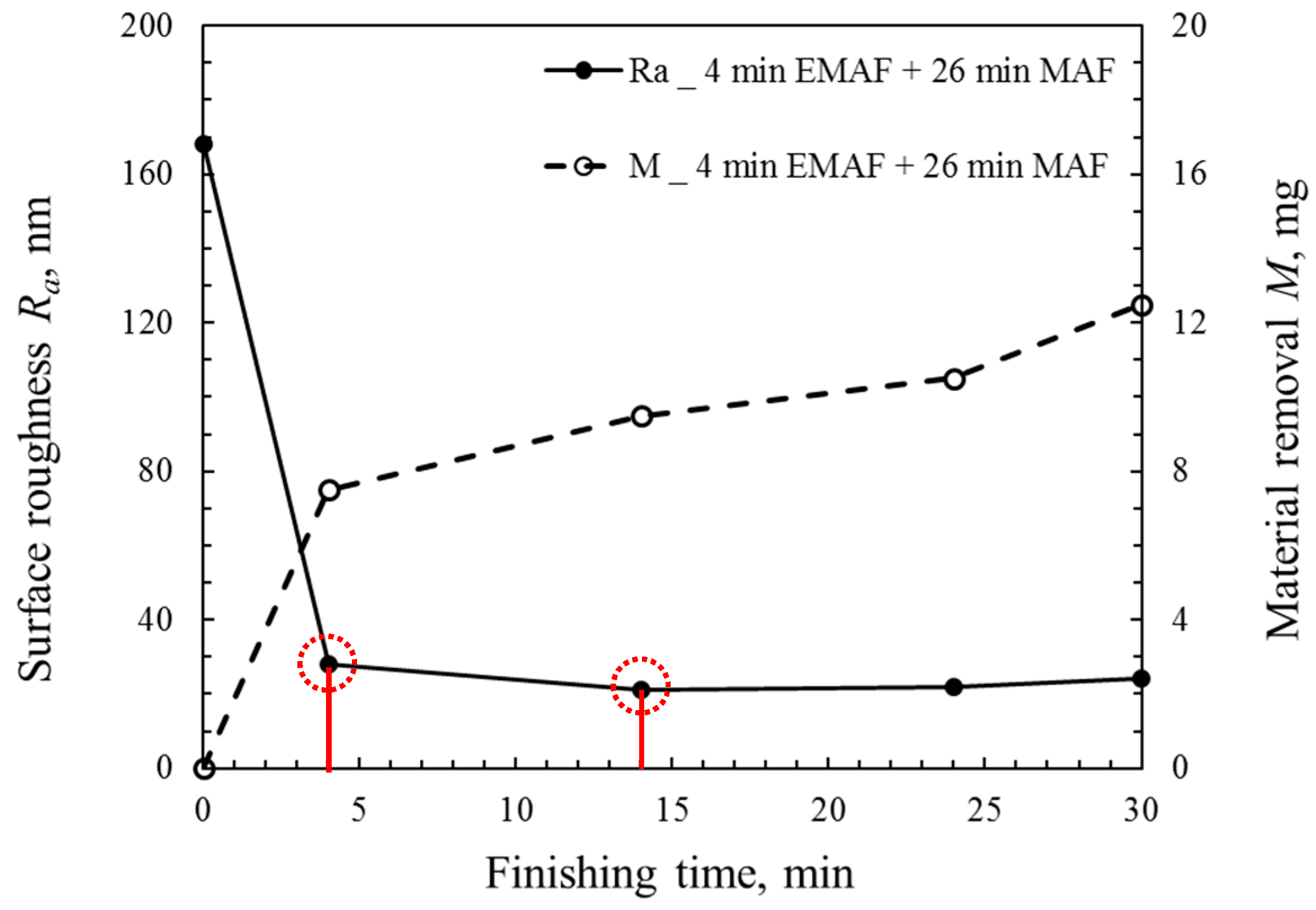
Figure 10 shows the change in surface roughness Ra and material removal M under the condition of the combination of the 4-min EMAF step and 26-min MAF step. It can be noted that the surface roughness Ra drastically decreased in the EMAF step, while the material removal M in the EMAF step was obviously more than the material removal M in the MAF step. The material removal M was approximately 7.5 g in the 4-min EMAF step; the material removal M was less than 5 g in the 26-min MAF step. In other words, the material removal rate in the 4-min EMAF process was nearly 9.75 times that in the 26-min MAF step. Furthermore, the surface roughness Ra could be reduced to less than 30 nm at the 4-min EMAF step. Then, it could be reduced to 20 nm at the 10-min MAF step, after which there was little change to the surface roughness Ra. Therefore, it was found that the optimal surface accuracy can be obtained via the 14-min EMAF process under the condition of the combination of a 4-min EMAF step and a 26-min MAF step.
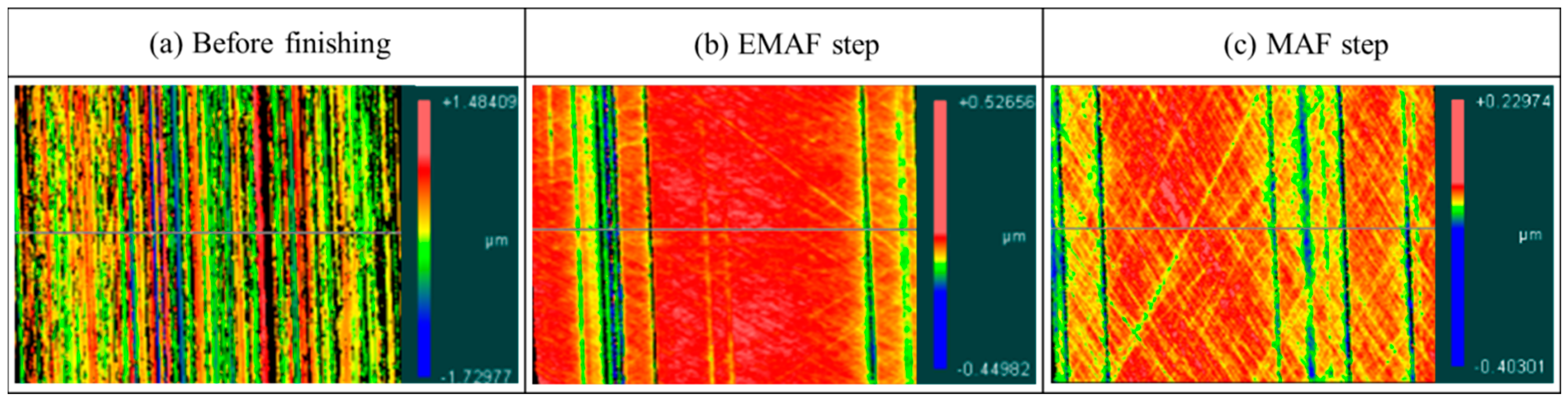
The non-contact 3D measurements of the original surface and finished surface after different finishing steps under the condition of the combination of the 4-min EMAF step and 26-min MAF step are shown in Figure 11. Through the macroscopic confocal image (a), many dense initial hairlines can be clearly seen on the workpiece surface before finishing. It can be seen that the protruding part of the original surface can be rapidly removed after the EMAF step, according to the macroscopic confocal image (b). Yet, some deep concave hairlines were still retained on the finished surface after the EMAF step. Then, it was found that the depth of residual concave hairlines obviously became shallow after the MAF step, as shown in the macroscopic confocal image (c). Yet, the number of scratched hairlines on the finished surface slightly increased after the MAF step. This is because the finished surface was excessively polished by the magnetic brush.
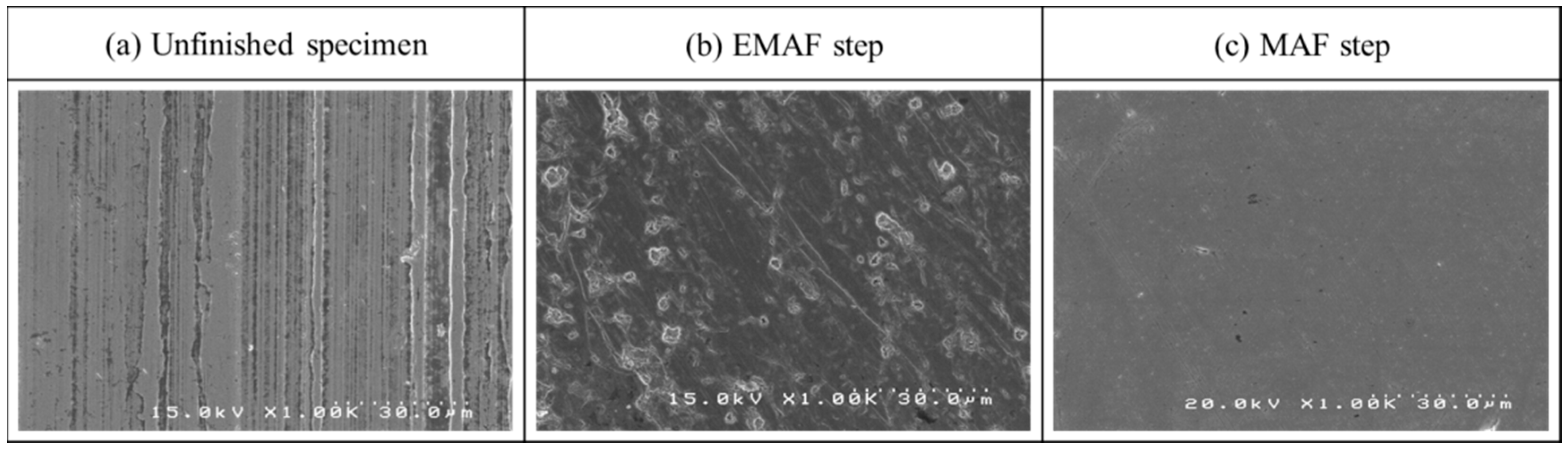
SEM photographs of the original surface before the EMAF process are shown in Figure 12a. The initial hairline of the unfinished surface can be clearly seen through the SEM photographs. Figure 12b shows an SEM photograph of the finished surface after the 4-min EMAF step. It was found that a small amount of micropores still existed on the finished surface. Moreover, this also indicated that the action of the MAF process cannot completely remove the passive films generated by the electrolytic process. An SEM photograph of the finished surface after the 26-min MAF step is shown in Figure 12c. Compared with the original surface of the workpiece, it can be clearly seen that the initial hairline of the surface was almost completely removed. Furthermore, it also can be confirmed that the MAF step plays an essential role in achieving precision machining in the EMAF process.
4.5. Discussions
The magnetic brush is formed on a magnetic pole through mixed magnetic abrasive orderly arrangements in the direction of the magnetic field lines. A single magnetic particle along the magnetic equipotential line direction generates a force Fx and along the magnetic force line direction generates a force Fy, which are calculated by Equations (1) and (2) as follows:
where К is the correction coefficient of the volume, D is the diameter of the magnetic particle, χ is the susceptibility of the magnetic particle, μ0 is the permeability of the vacuum, H is the magnetic field intensity, and and are the gradients of the magnetic field intensity in the x and y directions, respectively. The magnetic field intensity H as an important parameter for magnetic force Fx and Fy, and can be calculated by the following equation:
where B is the magnetic flux density and μ is the magnetic permeability of the medium. It is not difficult to see that the magnetic intensity B directly affect the magnetic force. Therefore, different shapes of machining tools have different mechanical finishing characteristics.
Fx = КD3χμ0H(∂H/∂x)
Fy = КD3χμ0H(∂H/∂y)
H = B/μ
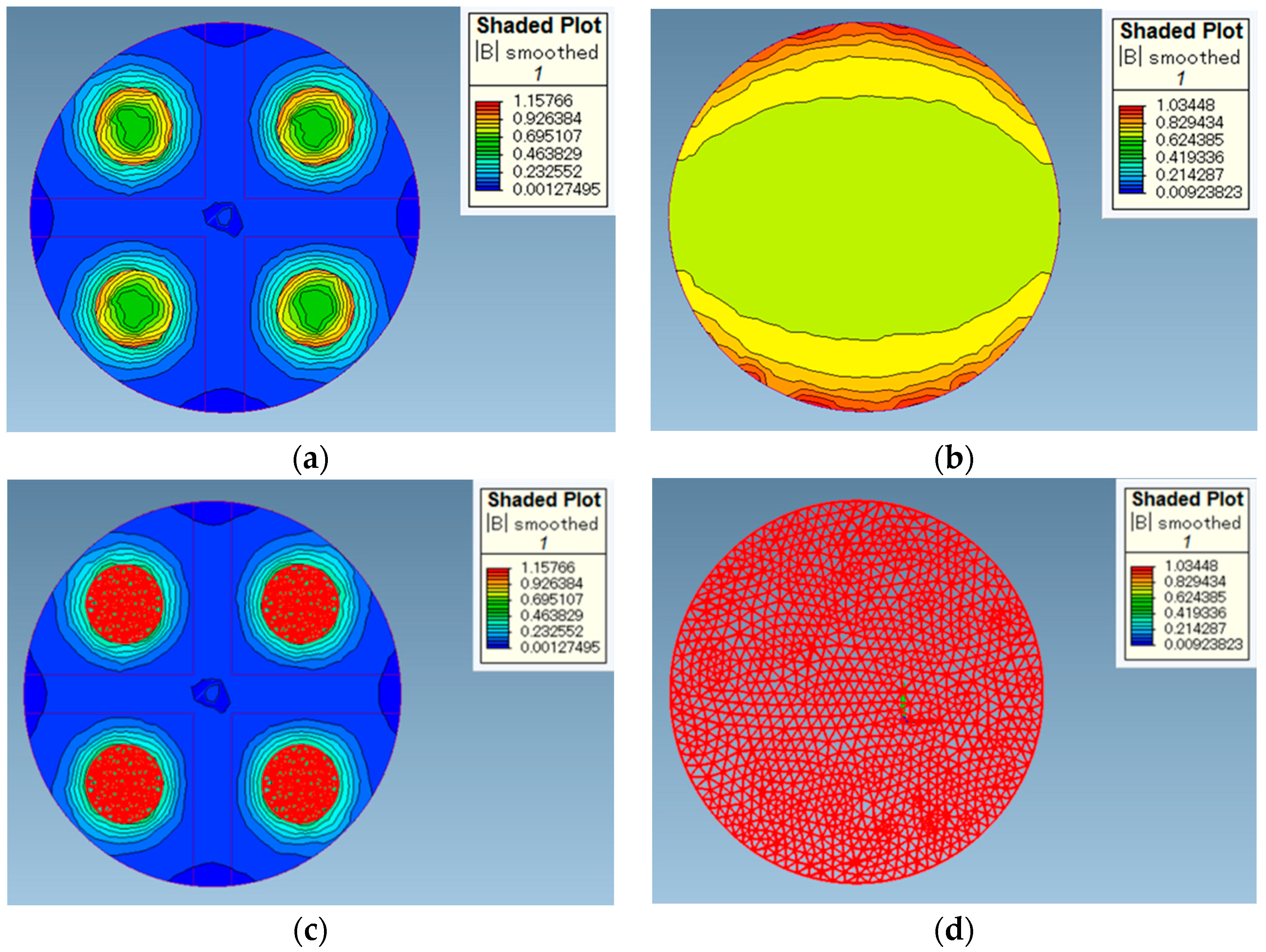
According to Equation (3), it can be seen that magnetic field strength H is proportional to the magnetic flux density B. Figure 13 shows the analysis of the magnetic flux density of the electrolytic magnetic compound machining tool and traditional magnetic machining tool, conducted using Magnet Version 7 software. The maximum element size of the mesh was set to 0.001 m. Figure 13a shows that the magnetic flux density of the electrolytic magnetic compound machining tool was relatively strong at the magnetic poles; the magnetic flux density at the magnetic pole edge was approximately 1 T and the magnetic flux density at the magnetic pole center was approximately 0.5 T. Additionally, the magnetic flux density gradually weakened farther away from the magnetic poles. Figure 13b shows that the magnetic flux density (approximately 1 T) of the traditional magnetic machining tool was relatively strong on the edge of the magnetic pole, whit it (approximately 0.7 T) was relatively weak at the center of the magnetic pole. Figure 13c,d respectively shows the analysis of the magnetic flux density with mesh grid for the electrolytic magnetic compound machining tool and traditional magnetic machining tool. It was noted that the overall magnetic field strength of the electrolytic magnetic compound tool was obviously smaller than that of the traditional magnetic machining tool by comparing analytical results. In other words, it can be regarded that the mechanical finishing characteristics of the electrolytic magnetic compound tool were worse than those of the traditional magnetic machining tool.
Though the overall magnetic field strength of the electrolytic magnetic compound tool was obviously smaller than that of the traditional magnetic machining tool, both the surface quality and material removal rate were very significant when using the electrolytic magnetic compound machining tool in the EAMF step. This is because the generated electrolytic action by the electrode of the compound machining tool effectively made up for the lack of magnetic force generated at the magnetic poles. Yet, the surface roughness reached a minimum when the finishing time was 14 min for the EMAF process. This is probably due to the effects of the electrolytic process and magnetic abrasive that reached the finishing balance. Hence, the surface roughness no longer declined. Since a large amount of metal ions dissociated from the surface of the workpiece by the electrolytic reactions in the EMAF step, the material removal rate in the 4-min EMAF step was higher than that in the 26-min MAF step.
5. Conclusions
This paper mainly reported the investigation of the mechanical finishing characteristics of the electrolytic magnetic compound machining tool and the experimental results of the EMAF process under the condition of the combination of a 4-min EMAF step and a 26-min MAF step. The main conclusions can be summarized as follows:
- The mechanical finishing characteristics of the electrolytic magnetic compound machining tool were determined through MAF process experiments and the analysis of the magnetic field strength. The experimental results of the MAF process show that a smaller surface roughness Ra and more material removal M can be obtained at a relatively higher rotational speed (450 rpm) and a relatively smaller working gap (1 mm) for the compound machining tool. Furthermore, the combination of 149-μm iron powder and #8000 WA particles can be regarded as the optimal mixed magnetic abrasive for the compound machining tool.
- Through the experimental results of the EMAF process under the condition of the combination of a 4-min EMAF step and a 26-min MAF step, it can be confirmed that the surface roughness Ra drastically decreased in the EMAF step; the material removal M in the EMAF step was nearly 9.75 times that in the MAF step. Moreover, it was also recognized that the surface roughness Ra can be reduced to less than 30 nm by the 4-min EMAF step. Then, the surface roughness Ra can be reduced to 20 nm by the 10-min MAF step. In other words, the surface roughness Ra can reach 20 nm from the original surface roughness Ra of 178 nm after the 14-min EMAF process.
- Since the overall magnetic field strength of the electrolytic magnetic compound tool was obviously smaller than that of the traditional magnetic machining tool, the mechanical finishing characteristics of the developed electrolytic magnetic compound machining tool were worse than those of the traditional magnetic machining tool. However, the electrolytic action generated by the electrode of the compound machining tool was effectively able to make up for the lack of magnetic force generated at the magnetic poles.
Author Contributions
Y.Z. conceived of the presented idea. X.S. designed the experimental set-up, conducted the experiments and analyzed the magnetic flux density of the electrolytic magnetic compound machining tool and traditional magnetic machining tool. After that, X.S. also wrote the manuscript and responded the reviewer comments. The two authors provided critical feedback and helped shape the research and manuscript.
Funding
This research received no external funding.
Acknowledgments
We acknowledge valuable contributions and support from the Utsunomiya University Creative Department for Innovation (CDI). We also acknowledge partial contribution from graduates Takumi Kojo for this study.
Conflicts of Interest
The authors declare no conflict of interest.
References
- Shinmura, T.; Takazawa, K.; Hatano, E.; Matsunaga, M. Study on magnetic abrasive finishing. Ann. CIRP 1990, 39, 325–328. [Google Scholar] [CrossRef]
- Ihar, I.; Nakano, E.; McLamore, E.; Schueller, J.K.; Toyoda, K.; Umetsu, K.; Yamaguchi, H. Cleanability of milk deposits on inner stainless steel tubing surfaces prepared by magnetic abrasive finishing. Int. J. Eng. Agric. Environ. Food 2017, 10, 63–68. [Google Scholar] [CrossRef]
- Hashimoto, F.; Yamaguchi, H.; Krajnik, P.; Wegener, K.; Chaudhari, R.; Hoffmeister, H.W.; Kuster, F. Abrasive fine-finishing technology. CIRP Ann. Manuf. Technol. 2016, 65, 597–620. [Google Scholar] [CrossRef]
- Zou, Y.H.; Jiao, A.Y.; Aizawa, T. Study on plane magnetic abrasive finishing process-experimental and theoretical analysis on polishing trajectory. Adv. Mater. Res. 2010, 126, 1023–1028. [Google Scholar] [CrossRef]
- Martinez, S.; Lamikiz, A.; Ukar, E.; Calleja, A.; Arrizubieta, J.A.; Lopez de Lacalle, L.N. Analysis of the regimes in the scanner-based laser hardening process. Opt. Lasers Eng. 2017, 90, 72–80. [Google Scholar] [CrossRef]
- Tabernero, I.; Lamikiz, A.; Ukar, E.; Lopez de Lacalle, L.N.; Angulo, C.; Urbikain, G. Numerical simulation and experimental validation of powder flux distribution in coaxial laser cladding. J. Mater. Process. Technol. 2010, 210, 2125–2134. [Google Scholar] [CrossRef]
- Lopez de Lacalle, L.N.; Rodriguez, A.; Lamikiz, A.; Calleja, A.; Alberdi, R. Five-Axis Machining and Burnishing of Complex Parts for the Improvement of Surface Roughness. Mater. Manuf. Process. 2011, 26, 997–1003. [Google Scholar] [CrossRef]
- Sun, X.; Zou, Y.H. Development of magnetic abrasive finishing combined with electrolytic process for finishing SUS304 stainless steel plane. Int. J. Adv. Manuf. Technol. 2017, 92, 3373–3384. [Google Scholar] [CrossRef]
- Ridha, M.M.; Zou, Y.H.; Sugiyama, H. Development of a new internal finishing of tube by magnetic abrasive finishing process combined with electrochemical machining. Int. J. Mech. Eng. Appl. 2015, 3, 22–29. [Google Scholar]
- Sihag, N.; Kala, P.; Pandey, P.M. Chemo Assisted Magnetic Abrasive Finishing: Experimental Investigations. Procedia CIRP 2015, 26, 539–543. [Google Scholar] [CrossRef]
- Judal, K.B.; Yadava, V. A study of electrochemical magnetic abrasive machining process. Int. J. Manuf. Technol. Manag. 2013, 27, 142–153. [Google Scholar] [CrossRef]
- Liu, G.Y.; Guo, Z.N.; Jiang, S.Z.; Qu, N.S.; Li, Y.B. A study of processing Al 6061 with electrochemical magnetic abrasive finishing. Procedia CIRP 2014, 14, 234–238. [Google Scholar] [CrossRef]
- Sihag, N.; Kala, P.; Pandey, P.M. Experimental investigations of chemo-ultrasonic assisted magnetic abrasive finishing process. Int. J. Precis. Technol. 2015, 5, 246–260. [Google Scholar] [CrossRef]
- Pa, P.S. Super finishing with ultrasonic and magnetic assistance in electrochemical micro-machining. Electrochem. Acta 2009, 54, 6022–6027. [Google Scholar] [CrossRef]
- Fang, J.; Jin, Z.; Xu, W.; Shi, Y. Magnetic electrochemical finishing machining. J. Mater. Process. Technol. 2002, 129, 283–287. [Google Scholar] [CrossRef]
- Kim, J.D.; Xu, Y.M.; Kang, Y.H. Study on the characteristics of magneto-electrolytic-abrasive polishing by using the newly developed nonwoven-abrasive pads. Int. J. Mach. Tools Manuf. 1998, 38, 1031–1043. [Google Scholar] [CrossRef]
- Strehblow, H.H. Passivity of metals. Adv. Electrochem. Sci. Eng. 2003, 8, 271–374. [Google Scholar]
- Yasuo, K. Ultra-Precision Machining by Electrolytic Complex Method; Aipishi: Tokyo, Japan, 1994; pp. 111–116. (In Japanese) [Google Scholar]
Figure 1.
Schematic of the electrolytic/electrochemical magnetic abrasive finishing (EMAF) process.

Figure 2.
Three-dimensional views of the electrolytic magnetic compound machining tool.

Figure 3.
External photo of the experimental setup.

Figure 4.
Observed locations of surface specimen.

Figure 5.
Change in surface roughness Ra under the conditions of iron powder with different diameters mixed with different sizes of WA abrasive; comparison of the best experimental results under the conditions of iron powder with different diameters: (a) iron powder with a mean diameter of 330 μm mixed with different sizes of abrasive grains; (b) iron powder with a mean diameter of 149 μm mixed with different sizes of abrasive grains; (c) iron powder with a mean diameter of 75 μm mixed with different sizes of abrasive grains; (d) comparison of best experimental results under different diameters of iron powder.


Figure 6.
Change in surface roughness Ra and material removal M at the machining tool’s different rotational speeds in the 60-min MAF process.
Figure 6.
Change in surface roughness Ra and material removal M at the machining tool’s different rotational speeds in the 60-min MAF process.

Figure 7.
Macroscopic confocal images of the finished surface after the 60-min MAF process under the conditions of various rotational speeds of the machining tool.
Figure 7.
Macroscopic confocal images of the finished surface after the 60-min MAF process under the conditions of various rotational speeds of the machining tool.

Figure 8.
Change in surface roughness Ra and material removal M under different working gaps in the 60-min MAF process.
Figure 8.
Change in surface roughness Ra and material removal M under different working gaps in the 60-min MAF process.

Figure 9.
Macroscopic confocal images of the finished surface under the conditions of various working gaps after the 60-min MAF process.
Figure 9.
Macroscopic confocal images of the finished surface under the conditions of various working gaps after the 60-min MAF process.

Figure 10.
Change in surface roughness Ra and material removal M under the condition of the combination of the 4-min EMAF step and 26-min MAF step.
Figure 10.
Change in surface roughness Ra and material removal M under the condition of the combination of the 4-min EMAF step and 26-min MAF step.

Figure 11.
Non-contact three-dimensional (3D) measurement of the unfinished surface and finished surface after different finishing steps under the condition of the combination of the 4-min EMAF step and 26-min MAF step.
Figure 11.
Non-contact three-dimensional (3D) measurement of the unfinished surface and finished surface after different finishing steps under the condition of the combination of the 4-min EMAF step and 26-min MAF step.

Figure 12.
SEM images of the original surface and finished surface after different finishing steps.

Figure 13.
Using Magnet Version 7 software to analyze the magnetic flux density of the electrolytic magnetic compound machining tool and traditional magnetic machining tool: (a) magnetic flux density of electrolytic magnetic compound machining tool; (b) magnetic flux density of traditional magnetic machining tool; (c) magnetic flux density with mesh grid for electrolytic magnetic compound machining tool; (d) magnetic flux density with mesh grid for traditional magnetic machining tool.

Table 1.
Experimental conditions of the magnetic abrasive finishing (MAF) process.
| Workpiece | SUS304 Plane (100 × 100 × 1 mm) |
| Original Roughness Ra | 0.16~0.2 μm |
| Mixed Magnetic Abrasive | Electrolytic iron powder: 75 μm, 149 μm, 330 μm |
| WA particles: #4000, #6000, #8000, #10000 | |
| Oily grinding fluid | |
| Working Gap | 1 mm, 2 mm |
| Feeding Speed of Stage | 5 mm/s |
| Rotational Speed of Tool | 230 rpm, 450 rpm |
| Finishing Time | 60 min |
Table 2.
Experimental conditions of the EMAF process.
| Workpiece | SUS304 plane (100 × 100 × 1 mm) |
| Original Roughness Ra | 0.16~0.2 μm |
| Mixed Magnetic Abrasive | Electrolytic iron powder: 149 μm |
| WA particles: #8000 | |
| Oily grinding fluid | |
| Working Gap | 1 mm |
| Feeding Speed of Stage | 5 mm/s |
| Rotational Speed of Tool | 450 rpm |
| Working Voltage | 12 V |
| Electrolyte Concentration | NaNO3 electrolyte solution, 20 wt % |
| Finishing Time (30 min) | 4-min EMAF step + 26-min MAF step |
© 2018 by the authors. Licensee MDPI, Basel, Switzerland. This article is an open access article distributed under the terms and conditions of the Creative Commons Attribution (CC BY) license (http://creativecommons.org/licenses/by/4.0/).
Share and Cite
MDPI and ACS Style
Sun, X.; Zou, Y. Study on Electrolytic Magnetic Abrasive Finishing for Finishing Stainless Steel SUS304 Plane with a Special Compound Machining Tool. J. Manuf. Mater. Process. 2018, 2, 41. https://doi.org/10.3390/jmmp2030041
AMA Style
Sun X, Zou Y. Study on Electrolytic Magnetic Abrasive Finishing for Finishing Stainless Steel SUS304 Plane with a Special Compound Machining Tool. Journal of Manufacturing and Materials Processing. 2018; 2(3):41. https://doi.org/10.3390/jmmp2030041
Chicago/Turabian StyleSun, Xu, and Yanhua Zou. 2018. "Study on Electrolytic Magnetic Abrasive Finishing for Finishing Stainless Steel SUS304 Plane with a Special Compound Machining Tool" Journal of Manufacturing and Materials Processing 2, no. 3: 41. https://doi.org/10.3390/jmmp2030041