Article

Using the Segmented Iterative Learning Control Method to Generate Volumetric Error-Compensated Part Programs for Three-Axis CNC Milling Machine Tools

1
Institute of Mechatronic Engineering, National Taipei University of Technology, Taipei 10608, Taiwan
2
Department of Mechanical Engineering, National Taipei University of Technology, Taipei 10608, Taiwan
*
Author to whom correspondence should be addressed.
J. Manuf. Mater. Process. 2018, 2(3), 53; https://doi.org/10.3390/jmmp2030053
Submission received: 17 July 2018 / Revised: 10 August 2018 / Accepted: 10 August 2018 / Published: 13 August 2018
(This article belongs to the Special Issue New Findings and Approaches in Machining Processes)

Abstract

:
This study proposes using the iterative learning control method to adjust the volumetric error-compensated tool path, where the working volume motion accuracy of three-axis computerized numerical control (CNC) milling machine tools is increased by segmented modification of the part program. As the three-axis CNC milling machine tools generally have volumetric error of working volume, this study refers to the measured and established table of volumetric errors and uses the method of the modifying part program for volumetric error compensation of machine tools. This study proposes using part-program single-block positioning segmented for volumetric error compensation, as the generated compensated part program with multiple compensated blocks can effectively compensate the volumetric error of working volume in the tool moving process. In terms of the compensated tool path computing method, this study uses the iterative learning control (ILC) method and refers to compensated tool path and volumetric errors along the compensated tool path for iterative computation. Finally, a part program with multiple blocks is modified by the converged optimal compensated tool path, in order that the modified part program has higher-precision volumetric error compensation effect. The simulation result shows that the rate of improvement of error of the volumetric error compensation method proposed in this study is 70%. The result of cutting tests shows that the average rate of improvement of the straightness error of the test workpiece is 60%, while the average rate of improvement of height error is 80%. Therefore, the results of simulation and cutting tests can prove the feasibility of using the ILC method for segmented modification of the volumetric error-compensated part programs proposed in this study.

Graphical Abstract

1. Introduction

Manufacturing mechanical parts with higher accuracy has been the machining target of various computerized numerical control (CNC) machine tools through the ages, as the conventional pitch error measurement and compensation methods cannot meet the requirement. Using volumetric error measurement and implementing the geometric error compensation of machine tool working volume according to this measurement result have become an important method to improve machine tool machining quality [1,2,3,4,5]. There are six static geometric errors resulting from the axial movement of three-axis CNC milling machine tools, including displacement errors and angular errors. The displacement errors are linear displacement errors, vertical straightness errors, and horizontal straightness errors. The angular errors are pitch angular errors, yaw angular errors, and roll angular errors. In addition, the three-axis CNC milling machine tools have three squareness errors; therefore, for the three-axis CNC milling machine tools, there are 21 static geometric errors, leading to the volumetric error of the working volume of the machine tool [6,7,8,9,10].
The volumetric error has significant effect on the motion accuracy of a machine tool, and severely influences the geometric dimension accuracy of the workpiece, thus, measurement and compensation are required [11,12,13,14,15,16]. Xiang et al. [17] developed a volumetric error compensation technique for real-time and simultaneous compensation of the volumetric errors of multiple machine tools by integrating an ethernet distributed numerical control system with a generalized volumetric error kinematic model, which was also developed in this study. Due to the increased importance of integrating metrology systems to machine tools to online compensate volumetric errors of machine tools for improving machining efficiency and accuracy, Wang and Maropoulos [2] developed a real-time volumetric error compensation algorithm to improve the dynamic path accuracy of a machine tool using a laser tracker-assisted 3-axis positioning system. Holub et al. [18] identified volumetric errors of a small three-axis vertical machining center using a laser interferometer, and ballbar tests were used to validate the volumetric error compensation results. Later, Holub et al. [19] performed on-the-fly tracking experiments on the small three-axis machining center to measure the volumetric errors of the small three-axis machining center using a self-tracking interferometer, and then compared the measurement time and results with conventional trigger- or time-based measurements to show the superior performance of on-the-fly measurement. Circular tests based on ISO 230-4 were also employed for verification. Owing to the influence of thermal distortion on the manufacturing accuracy of large machine tools, Gomez–Acedo et al. [20] developed a thermal distortion compensation system using parametric state-space representation as the model architecture, and the Kalman filter as the estimator for the thermal drift of the machine tool center point for different spindle speeds and temperatures of the motor gearbox and room air, respectively. Later, Gomez–Acedo [21] developed a new methodology for the measurement of thermal distortion in large machine tools using a laser tracking interferometer to achieve low measurement uncertainty. The measurement method for the angular thermal distortion of the horizontal plane was also developed by referring to the temperatures of the machine headstock and column. López De Lacalle et al. [22] developed a methodology for the geometric accuracy estimation of five-axis machine tools using the Denavit–Hartenberg (DH) convention. The assembly errors were considered as the additional geometric parameters in DH transformation matrices in order to present the imperfect tool position in absolute reference system; therefore, the developed methodology can be applied to precisely estimate the dimensional errors of a manufactured workpiece. Based on the DH convention, Díaz–Tena et al. [23] developed a methodology for the geometric accuracy assessment of a multitasking machine consisting of a swivel tool-spindle head, two spindles, and a turret. Assembly errors were also considered as additional geometric parameters in transformation matrices in order to analyze the propagation and influence of assembly errors on the tool position and orientation in detail.
While there are high-end machine tool controllers with volumetric error compensation functionalities, it is expensive, which limits the generality of volumetric error compensation. To make the conventional machine tool controller have volumetric error compensation functionalities, the software compensation methods of part-program generation and modification have become an important trend to improve the influence of the volumetric error of machine tools [24,25,26,27]. Eskandari et al. [28] utilized a neuro-fuzzy algorithm to model the geometric errors of a machine tool using a laser interferometer, and then, developed a compensation method to modify the Numerical Control (NC) part program with G-codes, which consider the developed error model and the volumetric errors calculated through kinematic analysis of the machine tool.
Among numerous volumetric error software compensation methods, using CAD/CAM to generate part programs with volumetric error compensation generally has excessive complexity and difficult operation. The design of the modifying part program calculates the volumetric error and makes compensation according to the part program characterized tool moving path. While the method is simple, its volumetric error compensation effect is limited. As the volumetric errors induced by the tool moving process cannot be neglected, some studies segmented and compensated the tool moving path [29,30,31]. Zhu et al. [32] employed statistical analysis methods to extract the component errors of a machine tool, and then, a B-Spline mathematical model was further developed to represent component error functions using the least-squares fitting method. Here, the NC part program with initial G-codes was recursively subdivided and segmented according to the developed component error functions with the calculated deviation errors. In addition, in order to improve the volumetric error induced by the compensated tool path, some studies used the iteration method to compute more accurate tool moving paths for machine tools [29,30]. Based on the measurement and modeling of volumetric errors, Wang and Lin [27] developed a software-based error compensation method with an error interpolation scheme to improve machining accuracy of a machine tool by recursively compensating the cutting path and machining trajectory. Tool path deviation, as induced by the kinematic and geometric errors of a CNC machine tool, usually corrupts the dimensional accuracy of the machined mechanical parts; therefore, based on the developed error estimation model, Vahebi Nojedeh et al. [26] developed NC program editor software to modify and generate the errors the compensated NC program by recursively computing the compensated positions along the modified tool path. Lee et al. [33] developed a kind of capacitance-sensor to measure the five geometric errors of a miniaturized machine tool, and then, a volumetric error model was developed to synthesize and recursively compensate the geometric errors of the machine tool to efficiently improve its positioning accuracy.
While the iterative computation of the volumetric error-compensated tool moving path can effectively improve the influence of the volumetric errors in the tool moving process of a machine tool, the unit recursive gain may fail to effectively converge to appropriate compensated tool path positions due to the machine tool working volume error distribution. Therefore, this study refers to the measured and established table of volumetric errors, as based on the part-program modification method, to segment the tool moving path, and uses the concept of ILC (iterative learning control) adjustment to design a segmented compensation method for the volumetric error of the part program, meaning the part program can be modified to have volumetric error compensation effect with higher tool moving accuracy. This study uses the Laser Doppler Displacement Meter (LDDM) laser displacement measurement system and volumetric error analysis software to establish a table of the volumetric errors of the machine tool [34,35], and then, performs path segmentation according to the part program characterized tool moving path. Finally, the segmented tool moving path of the part program is iteratively adjusted according to the concept of ILC. The ILC registers the actuation input, system output, and output error information of the control system execution process through an iterative computation process as reference for adjusting the control system actuation input of the next iteration, in order that the output error can converge to a limited range within a limited number of iterative learning. According to the segmented tool moving path of the part program, this study uses the interpolation table of volumetric errors to compute the volumetric errors induced by the tool moving path, and modifies the segmented tool moving path according to the volumetric errors. At this point, to reduce the volumetric errors induced by the execution of the segmented tool moving path after modification, the segmented tool moving path is adjusted by ILC iteratively till it converges to the optimal segmented tool moving path.
The structure of this paper is described, as follows. Section 2 describes the experimental and measuring equipment used in this study. Section 3 describes the volumetric error compensation and calculation method proposed in this study, including computation for error compensation and application of the iterative learning control method. Section 4 tests volumetric error compensation and discusses the results, thus, the feasibility of the volumetric error compensation method, as proposed in this study, can be validated. Section 5 summarizes this paper.

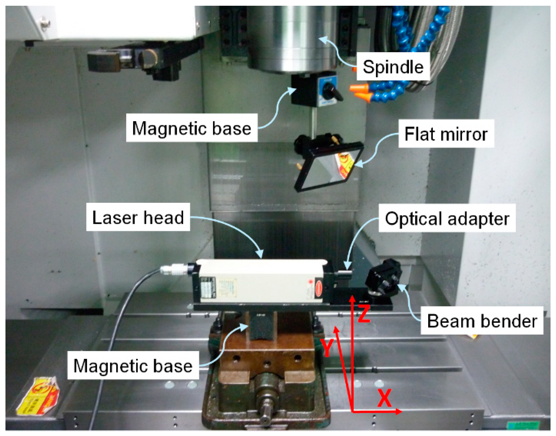
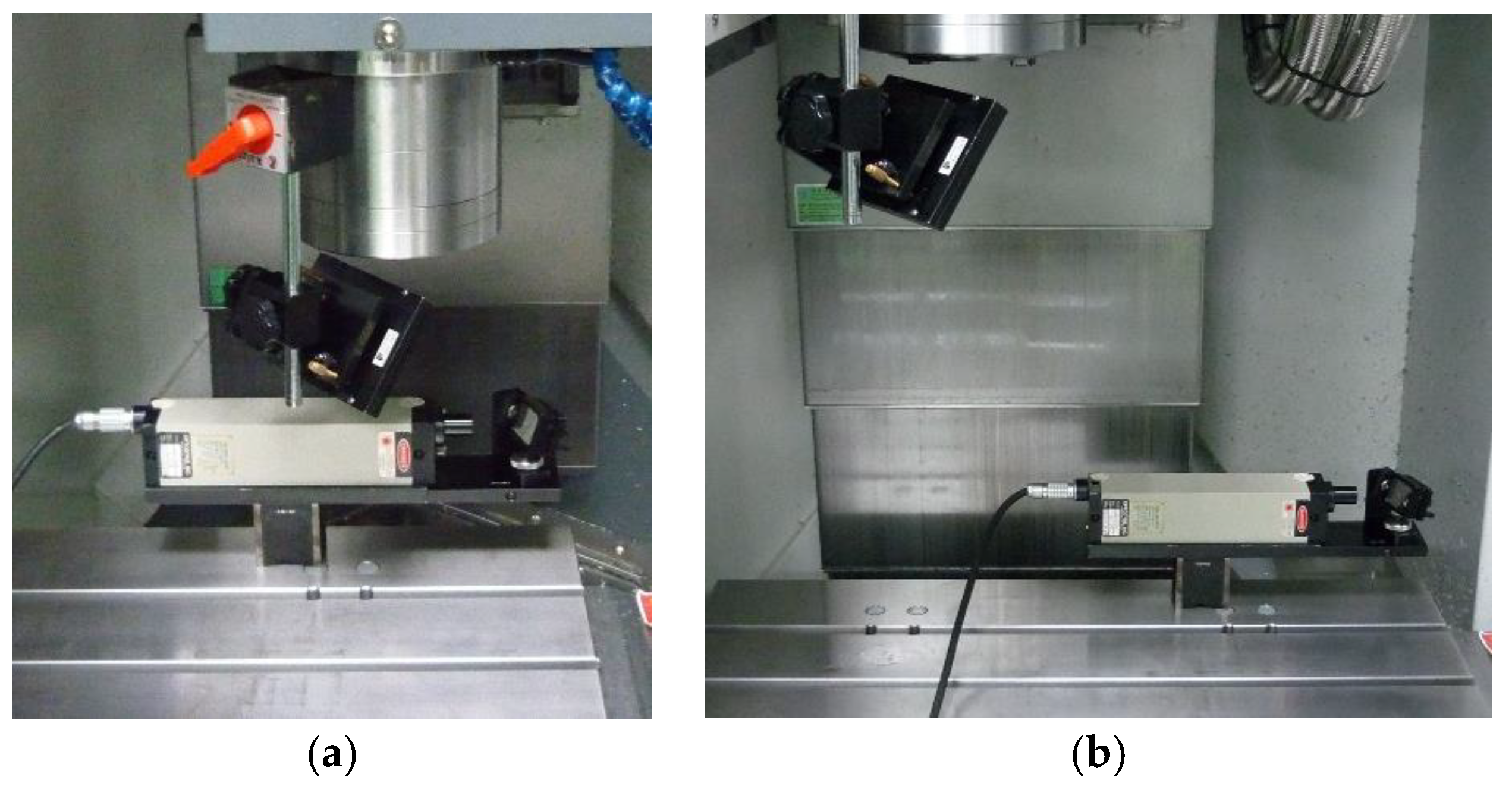
2. Introduction to Experimental System and Architecture

The three-axis CNC milling machine tool used in this study is shown in Figure 1. Its working volume is 560 × 410 × 450 mm3, the controller is a FANUC 32i series controller, which is suitable for the application of a high-speed CNC machine tool [36]. The machine tool uses a C-shaped mechanical structure; the Y-axis feed drive servomechanism is installed on the base, and the ballscrew drives the saddle. The X-axis feed drive servomechanism for driving the working table is installed on the Y-axis feed drive servomechanism, and the workpiece to be machined is fixed to the working table. The Z-axis feed drive servomechanism, which is perpendicular to the working table, is installed on the column to control the vertical movement of the spindle. The cutting tool used for machining is installed on the spindle.
The LDDM™ laser displacement measurement system used in this study is shown in Figure 2, which measures the volumetric error of machine tool working volume and generates the forward and reverse table of volumetric errors on each motion axis. The laser Doppler displacement meter, LDDM™, is an instrument system with 1/1,000,000 (1 ppm) displacement measurement accuracy. The maximum measurement range is 15 m, the standard resolution is 0.01 ìm, the highest measurement speed is 3600 mm/s, and the temperature range is 15.5 °C to 32 °C. In this study, all measurements and compensation processes were performed under similar temperature (approximately 20 °C) and air humidity (relative humidity approximately 50%) for a fair comparison. The measurement instrument for the cutting test is the NVC322 fully automatic vision measuring machine produced by 3DFAMILY Technology for workpiece straightness error measurement. The TESA MICRO-HITE Plus M350 height gauge produced by Chiyeung, is used for height error measurement.

3. Volumetric Error Calculation and Compensation

As CNC machine tools have many coordinate systems, the part-program coordinate system used in part program, as well as the machine coordinate system used in machine tool motion, are described in this study. Generally speaking, for convenient workpiece machining, the operator usually uses the part-program coordinate system for programming the part program according to the engineering drawing. The original setting of the coordinate system varies with the tool moving process or machining process. The machine coordinate system is the referential coordinate system for mechanical system motion and is a real coordinate system. The origin of the coordinate system (machine origin) is the reference point of the machine tool, which is usually determined by the machine tool manufacturer. In the workpiece machining process, the part-program coordinate system is sometimes different from the machine coordinate system. As the machine tool volumetric error measurement refers to the machine coordinate system, the measured values of errors are represented by their positions in the machine coordinate system, thus, this study performs segmented compensation of volumetric errors by the part-program modification method. The part program characterized tool moving path must be transformed from the part program coordinate system to the machine coordinate system, and then, the machine coordinate system refers to the measured and established table of volumetric errors to compute the appropriate volumetric error compensation positions and values. The general transformation of coordinate systems is applicable to the tool moving path transformation between part-program coordinate system and machine coordinate system [37].
When the part program characterized tool moving path is transformed from the part program coordinate system to the machine coordinate system, the calculation and compensation of volumetric error in the tool moving process are performed. As shown in Figure 3, if the tool is to move from current position R (machine coordinate system represented R ) to target position T (machine coordinate system represented T ), due to the influence of the volumetric error of the machine tool, the cutting tool moves to actual position P (machine coordinate system represented P ), which leads to PT tool moving position error. As the table of the volumetric errors of the machine tool has been measured and established, the tool moving position error PT can be calculated by the table of volumetric errors, which can be used as the reference for the calculation of volumetric error-compensated position Q (machine coordinate system represented Q ). The volumetric error-compensated position Q can be calculated according to the following steps:
(S1)
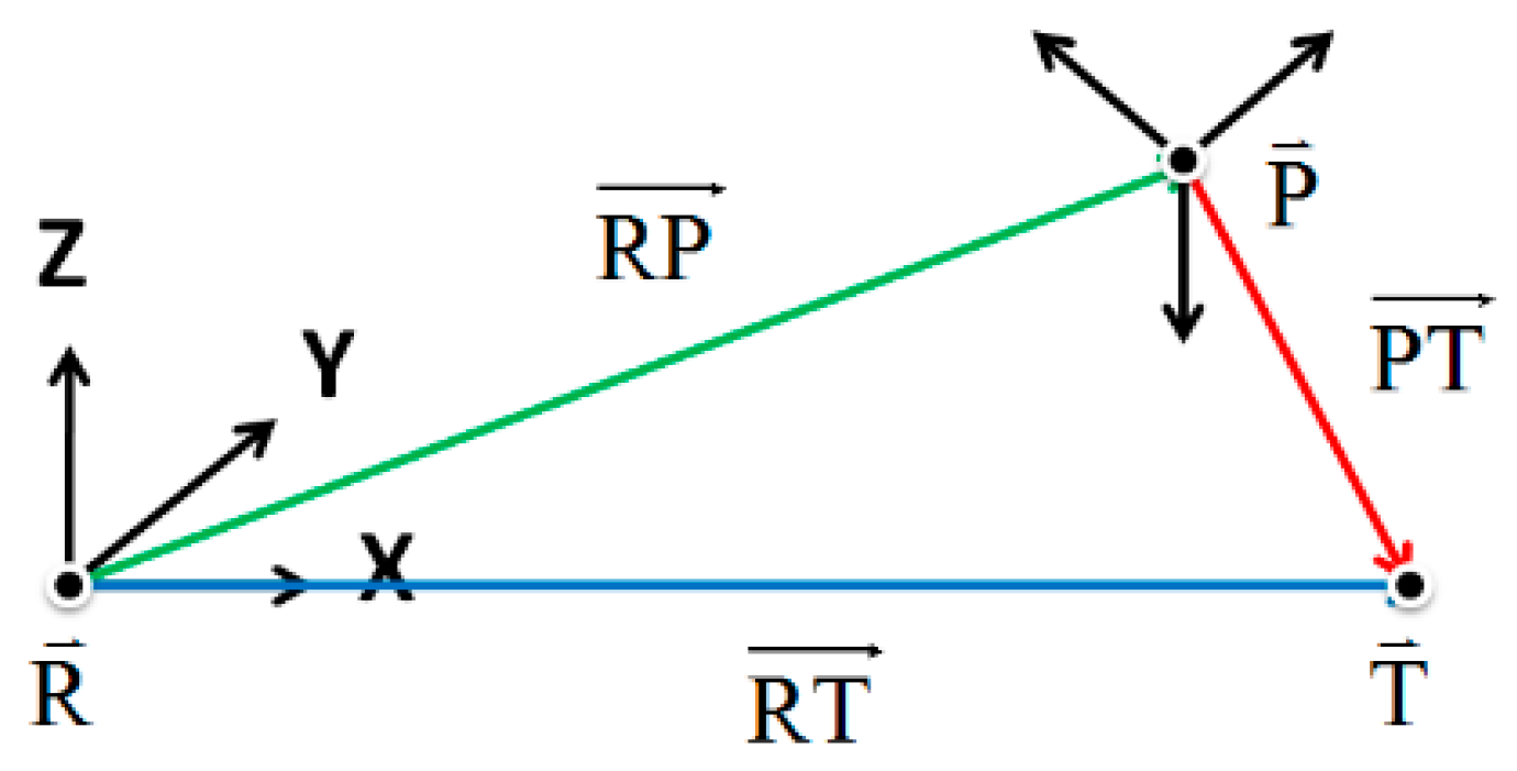
The tool moving direction from position R to position T (direction of RT vector) determines the load of the table of the forward volumetric errors or table of the reverse volumetric errors.
(S2)
The volumetric error vector E (= PT ) of the tool moves from position R to position T and is calculated by the loaded table of the volumetric errors.
(S3)
The tool moving T position and the calculated volumetric error vector E are added up to generate the volumetric error-compensated position Q .
The volumetric error vector E is calculated by interpolation according to the table of volumetric errors and RT vector. For example, as shown in Figure 4, if the RT vector means the X-axis moves from the origin position to the A position in the machine coordinate system, and it is 0 mm to 15 mm in the table of volumetric errors on X-axis, the X-axis movement results in the volumetric error on X-axis direction Dxx(A), expressed as Equation (1):
Dxx ( 15 ) Dxx ( 0 ) 15 0 = Dxx ( 15 ) Dxx ( A ) 15 A
Dxx(15) represents the volumetric error on the X-axis direction when the X-axis moves to 15 mm in the table of volumetric errors. Dxx(0) represents the volumetric error on the X-axis direction when X-axis is at 0 mm in the table of volumetric errors. Therefore, when volumetric error vector E is calculated, the volumetric error-compensated position Q can be calculated (machine coordinate system represented Q ), which is equal to position T (machine coordinate system represented T ) plus volumetric error vector E :
Q = T + E
While the volumetric error-compensated position Q can be calculated by Equation (2), there are two principal problems in practical application:
  • The compensation and calculation of Equation (2) only consider the error compensation of target position T, while the position error compensation of a tool moving from R to T is not considered. In other words, the position accuracy of the tool moving process cannot be guaranteed.
  • The compensation and calculation of Equation (2) disregard the effect of the volumetric error of the machine tool when the tool moves from position R to position Q . In other words, the actual position of the tool cannot be guaranteed, and the target position to be reached has position error.
To overcome the above problems, the original tool moving path is segmented. Figure 3 shows that target position T becomes the intermediate target position on the segmented tool moving path, meaning the position accuracy of the original tool moving process can be improved by the volumetric error compensation of the segmented tool moving path. To make the actual tool position and intermediate target position on the segmented tool moving path have small position error, differing from the present iterative computation method, this study uses the ILC concept to iteratively compute the volumetric error-compensated position.
ILC was proposed by Uchiyama [38], which adjusts or modifies the actuation input of a controlled plant by the iterative approaching control method, in order that the actual output of the controlled plant can converge to the referenced output within limited numbers of iterative, thus, it can be implemented in the manipulators and machine tools for executing repeated machine motions [39,40]. The development of the ILC theory receives the interest and attention of control field scholars; as its control structure is simple, it is applicable to both linear systems and nonlinear systems and can provide effective and practical solutions for repetitive tracking control and repetitive disturbance rejection problems [41,42,43]. ILC uses the current actuation input of a controlled plant and the execution output error as the calculation reference for next actuation input of the controlled plant, thus, there is appropriate control system execution output error correction ability, and the error decreases as the numbers of iterative learning increases. When the numbers of iterative learning approaches to infinity, the theoretical error approaches to zero. In this study, ILC is used for the iterative computation of the volumetric error-compensated tool position for the part program characterized tool moving path. When the calculated tool moving position error converges, the high-accuracy volumetric error-compensated tool position can be obtained, to modify the tool moving path of the part program. By referring to the volumetric error-compensated position computing equation, as shown in Equation (2), the iterative computation of the ILC volumetric error-compensated position is designed and expressed as Equation (3).
Q i + 1 = Q i + γ E i ,   i = 0 ,   1 ,   ,   n
where position Q i (machine coordinate system represented Q i ) represents No. (i) calculated volumetric error-compensated position, position Q i + 1 (machine coordinate system represented Q i + 1 ) represents No. (i + 1) calculated volumetric error-compensated position, E i represents the calculated volumetric error of a tool moving from the current position to No. (i) volumetric error-compensated position Q i , γ represents the learning factor, 0 < γ < 1 . Q 0 equals target position T (machine coordinate system represented T ), and E 0 represents the calculated volumetric error of the tool moving from the current position to target position T (machine coordinate system represented T ). The setting of learning factor γ affects the convergence of volumetric error-compensated position calculation. When the learning factor value is large, the volumetric error-compensated position calculation converges rapidly, and there is fluctuation, thus, it fails to achieve stable calculation results. When the learning factor value is small, while the volumetric error-compensated position calculation result is stable, the convergence rate is low. When learning factor γ is larger than 1, the volumetric error-compensated position calculation may fail to converge. As this study uses the offline computing method of Equation (3), a small learning factor value is used to guarantee stable volumetric error-compensated position calculation results. The calculation convergence of Equation (3) is judged based on whether the Euclidean norm of No. (i) calculated volumetric error E i decreases as the number of iterative computation increases. In other words, this study uses Equation (3) for the iterative computation of volumetric error-compensated position Q i , and checks whether the Euclidean norm ( E i ) of calculated volumetric error E i decreases as the number of iterative computation (i) increases. When Equation (3) calculates convergence iteratively, the converged volumetric error-compensated position is used as the tool moving path of the modified part program.

4. CNC Volumetric Error Compensation Experiment Results and Discussion

The machine tool is often provided with compensation parameters for general pitch error compensation; however, this pitch error compensation only compensates the displacement error induced by axial motion and neglects the displacement errors induced by other motion axes. Therefore, this study discusses the displacement error due to axial motion E xx , E yy , E zz , and considers the displacement errors induced by other motion axes E xy , E xz , E yx , E yz , E zx , E zy . Where Eij represents the displacement error on j-axis during i-axis movement. This study considers the aforesaid displacement errors and generates the error-compensated part program. The table of the volumetric errors of the experimental machine tool is measured by the LDDM laser Doppler displacement meter. The error distributions of the forward and reverse motions on each motion axis are shown in Figure 5.

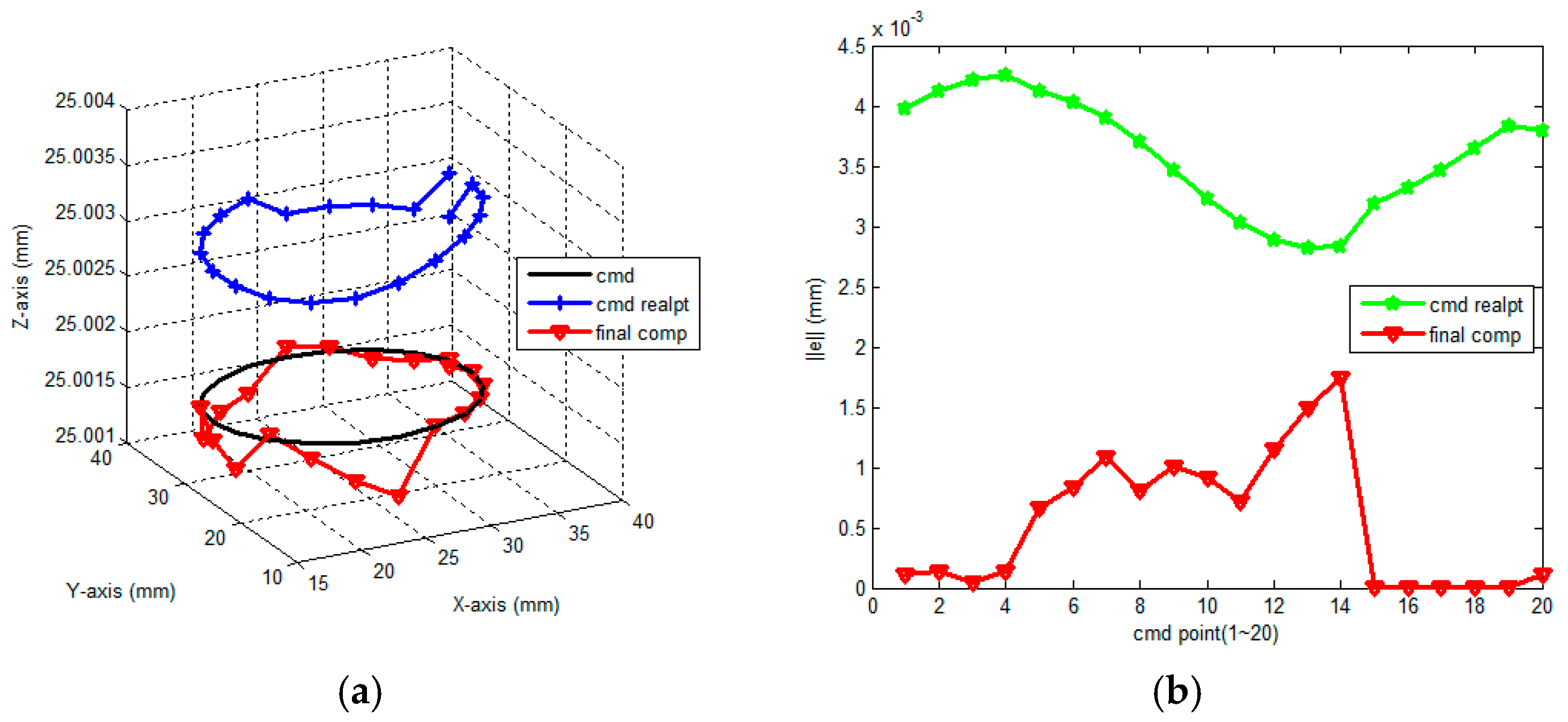
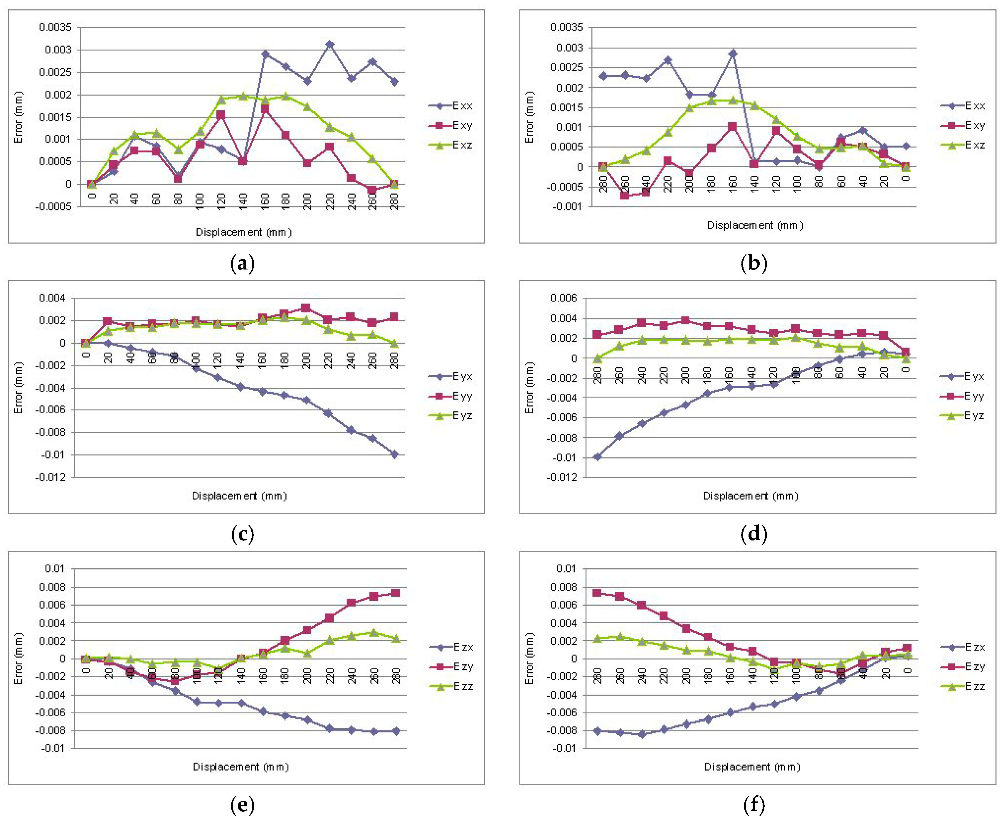
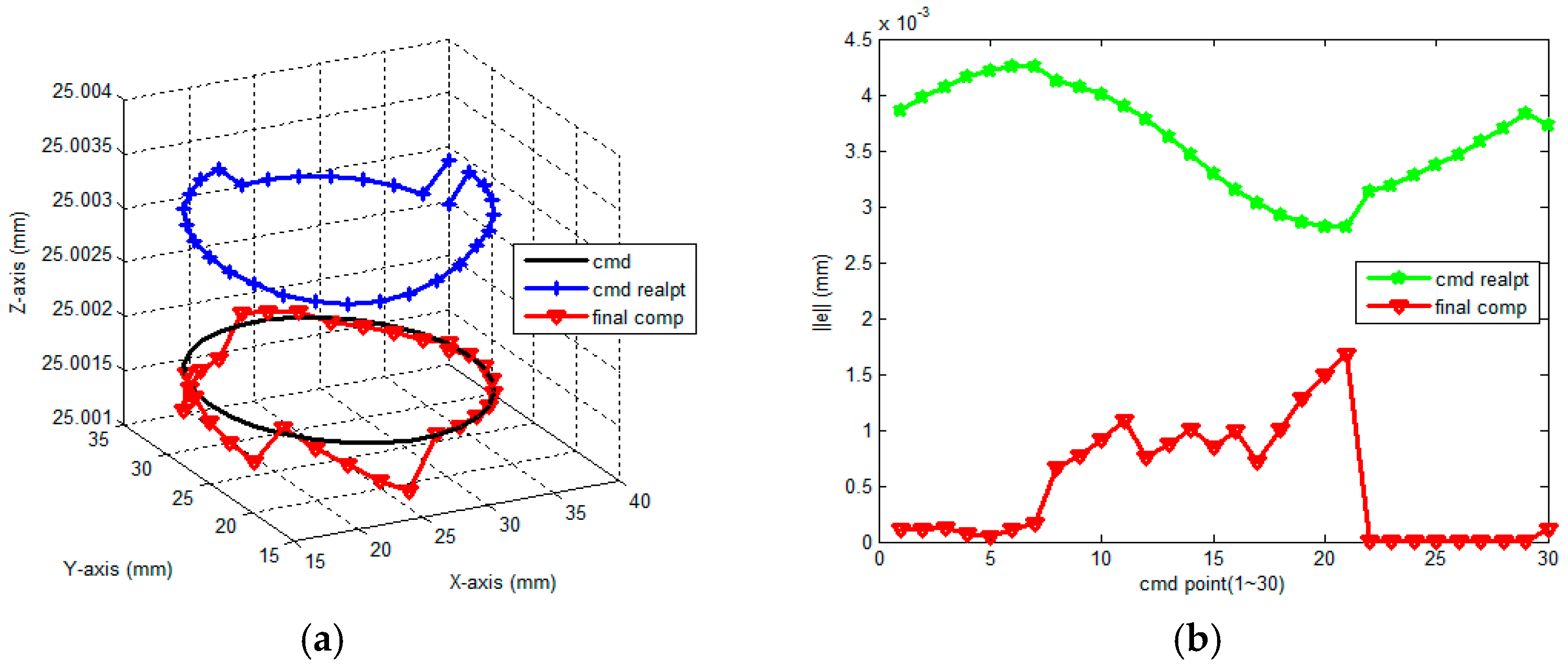
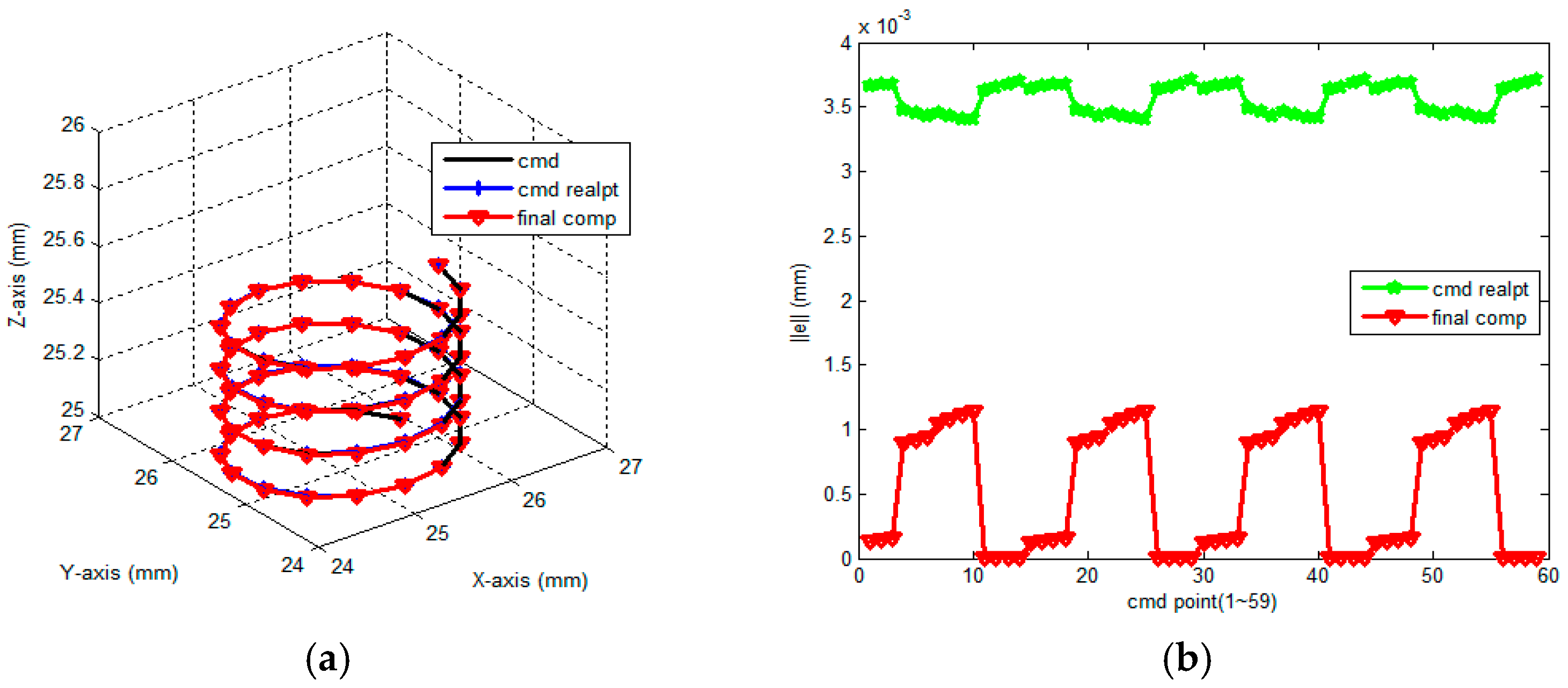
4.1. Simulation Results and Discussion

This study designs two different tool moving path simulations for observation, segmentation, and compensation for the circular path, and segmentation and compensation for the spiral path. Simulation 1 sets the tool movement path as a circle with a diameter of 20 mm, which is divided into 20 segment and 30 segment moving paths, as shown in Figure 6 and Figure 7, respectively. Simulation 2 sets the path as a spiral path with a diameter of 20 mm and a pitch of 1 mm, which is divided into 60 segments of moving paths, as shown in Figure 8. Table 1 shows the numerical analysis results of simulation. It is obvious that the segmented tool moving path position error root-mean-square value is improved after ILC compensation, where the rate of improvement is higher than 70%, demonstrating the feasibility and effect of the ILC volumetric error compensation computation method, as designed in this study, on the volumetric error compensation of a three-axis CNC milling machine tool. In addition, according to the analysis of the number of segments on the tool moving path, the larger the number of segments, the better the volumetric error compensation effect. However, many segments have limited compensation effect on the volumetric error, as it prolongs the computation time of compensation method on the contrary. Therefore, the position of a single block of the part program shall not be excessively segmented in practical application.

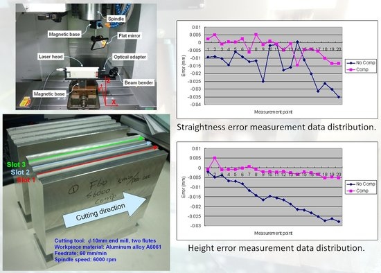
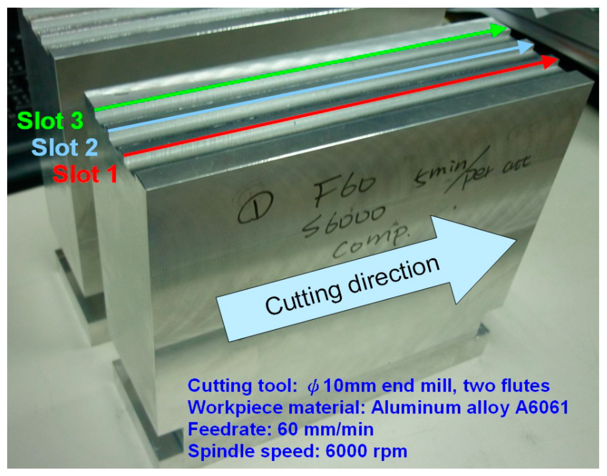
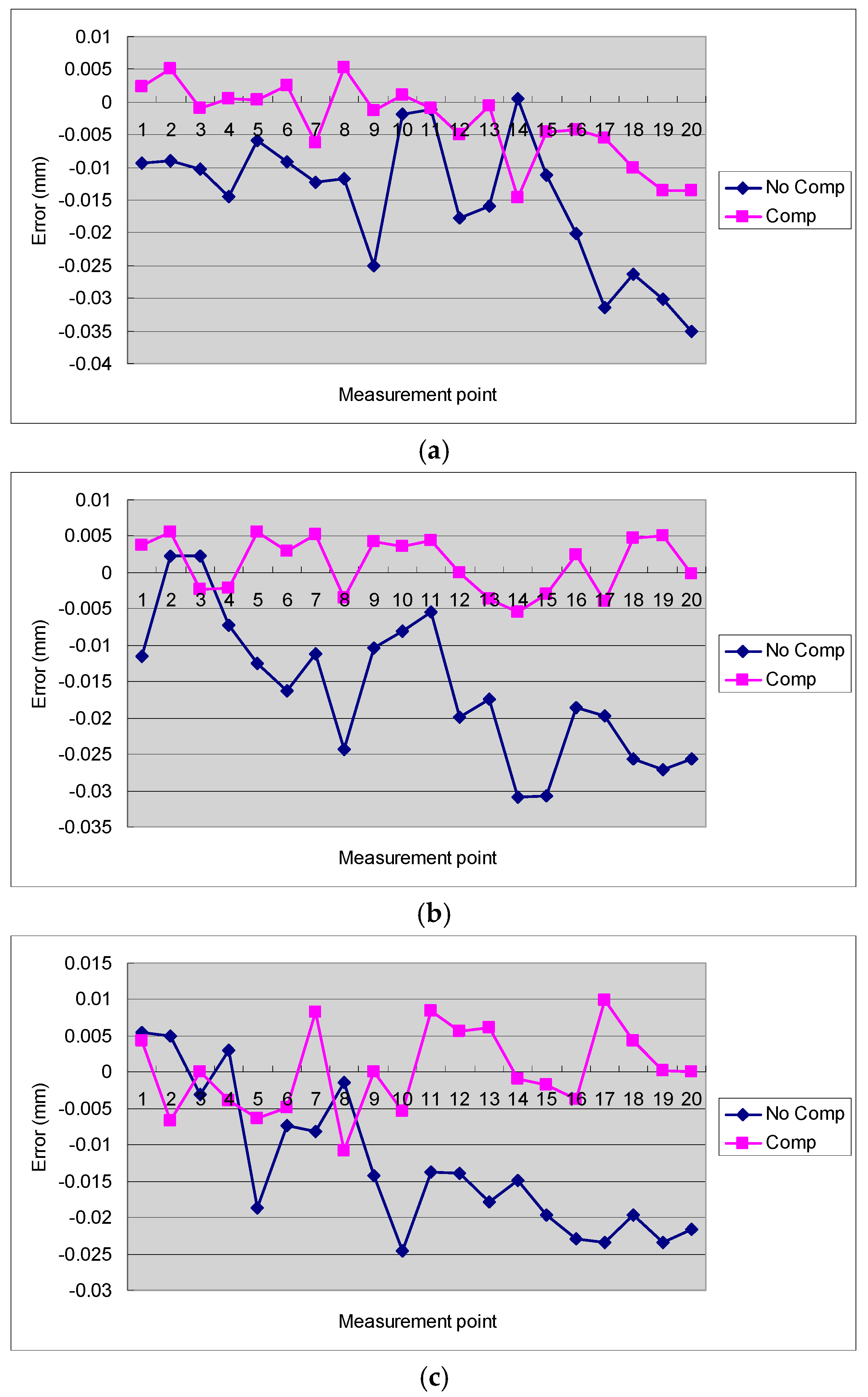
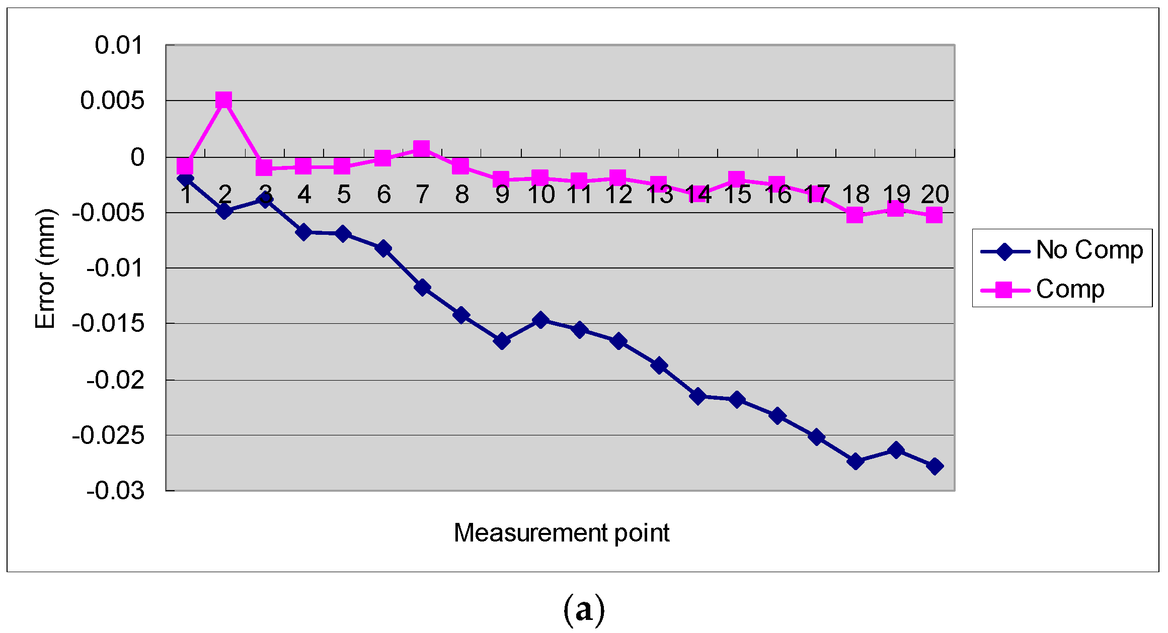
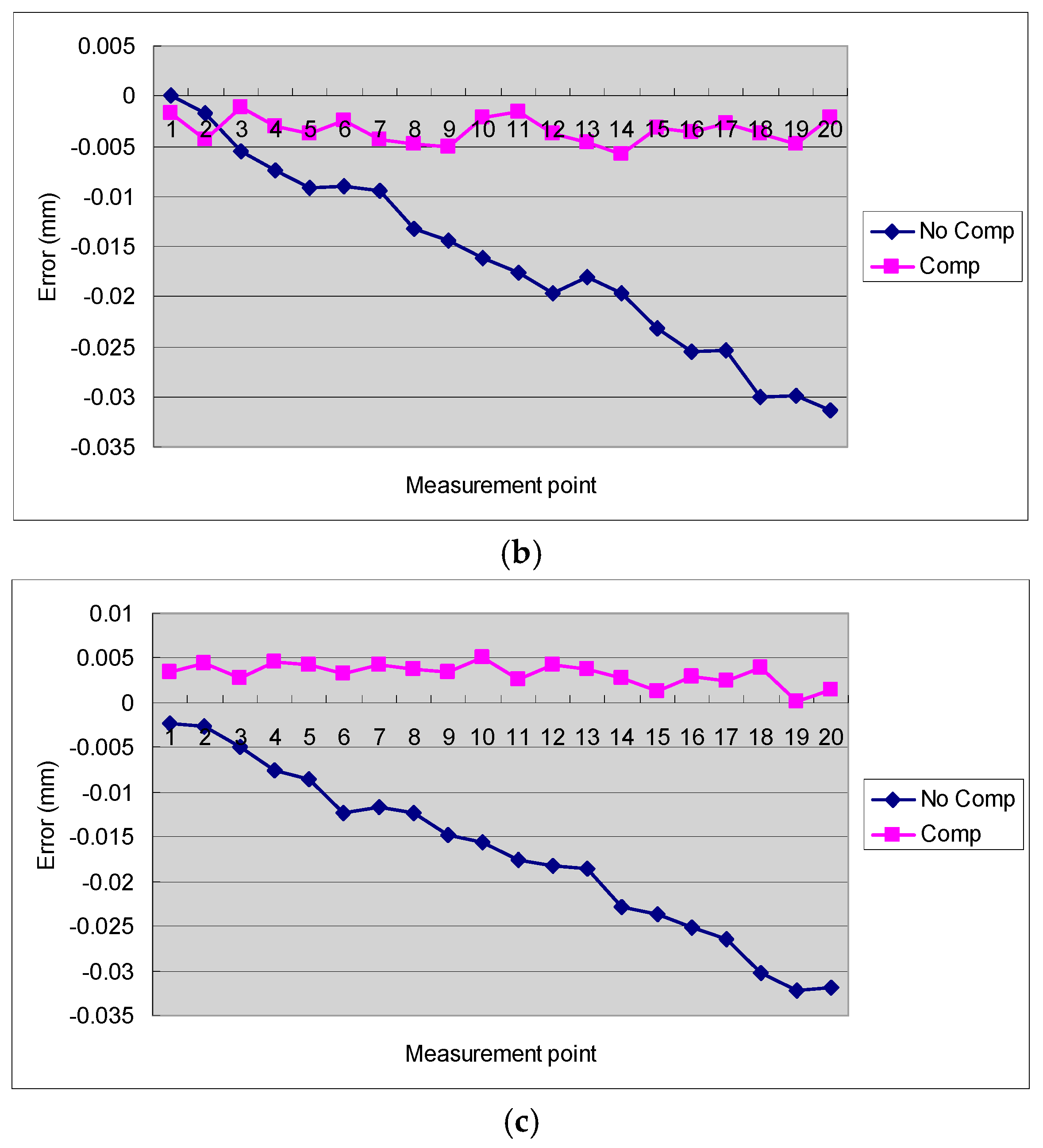
4.2. Discussion of the Results of Cutting Tests

This study uses three-axis CNC milling machine tool slot machining to detect the straightness error and height error of a workpiece to develop technical identification. The machining results are shown in Figure 9 and Table 2. The cutting tool for experimentation is a ø10 mm end mill with two flutes, and the workpiece material is aluminum alloy A6061. According to the data plot of the machining results, the degree of error convergence is known, and the relationship between the table of volumetric errors and the actual machining results can be observed. Figure 10 shows the side edge straightness measurement data distribution of three machined slots. Figure 11 shows the height measurement data distribution of the bottom surface of three machined slots. The experimental results show that the compensated tool moving path has better machining results, the optimum rate of improvement of the straightness error is 79.03%, the minimum rate of improvement is 62.57%, and the average rate of improvement is 68.87%. The optimum rate of improvement of height error is 83.62%, the minimum rate of improvement is 80.21%, and the average rate of improvement is 81.90%. In addition, the workpiece measurement result shows that the position error of straight cutting increases gradually. However, after volumetric error compensation, the distribution of position errors diminishes obviously, and fluctuates nearby the zero-error value in the smaller error range. Therefore, the volumetric error compensation method designed in this study can effectively reduce the volumetric errors in the tool moving of a three-axis CNC milling machine tool.

5. Conclusions

This study proposed the use of ILC to adjust the compensated tool path for the 21 volumetric errors in three-axis CNC milling machine tools, to increase the error compensation accuracy of the modified part program. The main conclusions of this study are as follows.
  • The volumetric error of the working volume of the three-axis CNC milling machine tool strongly influences the geometric dimension accuracy of the workpiece. The volumetric error compensation therefore becomes an issue that high-precision mechanical parts manufacturers must consider.
  • Existing part-program modification methods only consider the compensation of the position of a single block of a part program but neglect the movement bias induced by volumetric error in the tool moving process, which leads to limited volumetric error compensation effect.
  • In this study, the position of a single block of a part program was segmented, and volumetric error compensation was implemented for the tool moving position in each segment to generate a part program with multiple compensated blocks. The proposed compensation method can effectively compensate for volumetric errors in the tool moving process.
  • In addition, this study used the ILC concept and referred to the present compensated tool path and volumetric error induced by the compensated tool path to calculate the next compensated tool path. Therefore, the optimum compensated tool path can be obtained by the iterative computation of the compensated tool path.
  • To validate the effect of the proposed segmented volumetric error compensation, the measured and established table of volumetric errors was used for path simulation and cutting tests. Both the simulation and experimental results prove the feasibility of using the ILC method for the segmented modification of the volumetric error-compensated tool path.
  • Several cutting tests were performed on a three-axis CNC milling machine tool. The experimental results showed that the average rate of improvement of the straightness error of the proposed volumetric error compensation method is higher than 60% while the rate of improvement of the height error is higher than 80%.

Author Contributions

Investigation, Y.-C.L.; Investigation, Supervision, S.-S.Y.

Funding

This research was funded in part by the Ministry of Science and Technology, Taiwan, under Contract MOST104-2221-E-027-132 and MOST103-2218-E-009-027-MY2.

Acknowledgments

The authors would like to thank representatives from the 3DFAMILY Technology for their beneficial discussions with the project team. The authors would also like to thank Chen-Chou Chung (Ford Lio Ho Motor Company) for his valuable comments and suggestions on volumetric error compensation of CNC milling machine tools.

Conflicts of Interest

The authors declare no conflict of interest.

References

  1. Zou, X.; Zhao, X.; Li, G.; Li, Z.; Sun, T. Sensitivity analysis using a variance-based method for a three-axis diamond turning machine. Int. J. Adv. Manuf. Technol. 2017, 92, 4429–4443. [Google Scholar] [CrossRef]
  2. Wang, Z.; Maropoulos, P.G. Real-time laser tracker compensation of a 3-axis positioning system—Dynamic accuracy characterization. Int. J. Adv. Manuf. Technol. 2016, 84, 1413–1420. [Google Scholar] [CrossRef] [Green Version]
  3. Uekita, M.; Takaya, Y. On-machine dimensional measurement of large parts by compensating for volumetric errors of machine tools. Precis. Eng. 2016, 43, 200–210. [Google Scholar] [CrossRef]
  4. Wang, K.; Sheng, X.; Kang, R. Volumetric error modelling, measurement, and compensation for an integrated measurement-processing machine tool. Proc. Inst. Mech. Eng. Part C J. Mech. Eng. Sci. 2010, 224, 2477–2486. [Google Scholar] [CrossRef]
  5. Fletcher, S.; Postlethwaite, S.R.; Ford, D.G. Volumetric compensation through the machine controller. Laser Metrol. Mach. Perform. V 2001, 34, 321–330. [Google Scholar]
  6. Li, D.; Feng, P.; Zhang, J.; Yu, D.; Wu, Z. An identification method for key geometric errors of machine tool based on matrix differential and experimental test. Proc. Inst. Mech. Eng. Part C J. Mech. Eng. Sci. 2014, 228, 3141–3155. [Google Scholar] [CrossRef]
  7. Okafor, A.C.; Ertekin, Y.M. Derivation of machine tool error models and error compensation procedure for three axes vertical machining center using rigid body kinematics. Int. J. Mach. Tools Manuf. 2000, 40, 1199–1213. [Google Scholar] [CrossRef]
  8. Chen, J.S.; Kou, T.W.; Chiou, S.H. Geometric error calibration of multi-axis machines using an auto-alignment laser interferometer. Precis. Eng. 1999, 23, 243–252. [Google Scholar] [CrossRef]
  9. Knapp, W.; Matthias, E. Test of the three-dimensional uncertainty of machine tools and measuring machines and its relation to the machine errors. CIRP Ann. Manuf. Technol. 1983, 32, 459–464. [Google Scholar] [CrossRef]
  10. Ni, J.; Wu, S.M. On-line measurement technique for machine volumetric error compensation. J. Eng. Ind. Trans. ASME 1993, 115, 85–92. [Google Scholar] [CrossRef]
  11. Ibaraki, S.; Knapp, W. Indirect measurement of volumetric accuracy for three-axis and five-axis machine tools: A review. Int. J. Autom. Technol. 2012, 6, 110–124. [Google Scholar] [CrossRef]
  12. Majda, P. Modeling of geometric errors of linear guideway and their influence on joint kinematic error in machine tools. Precis. Eng. 2012, 36, 369–378. [Google Scholar] [CrossRef]
  13. He, Z.; Fu, J.; Yao, X.; Qian, W. Volumetric error identification for CNC machine tool based on multi-body system and vector diagonal measurement. In Proceedings of the 2010 International Conference on Mechanic Automation and Control Engineering, Wuhan, China, 26–28 June 2010; pp. 3345–3349. [Google Scholar]
  14. Jung, J.H.; Choi, J.P.; Lee, S.J. Machining accuracy enhancement by compensating for volumetric errors of a machine tool and on-machine measurement. J. Mater. Process. Technol. 2006, 174, 56–66. [Google Scholar] [CrossRef]
  15. Ahn, K.G.; Min, B.K.; Pasek, Z.J. Modeling and compensation of geometric errors in simultaneous cutting using a multi-spindle machine tool. Int. J. Adv. Manuf. Technol. 2006, 29, 929–939. [Google Scholar] [CrossRef]
  16. Yang, S.H.; Kim, K.H.; Park, Y.K.; Lee, S.G. Error analysis and compensation for the volumetric errors of a vertical machining centre using a hemispherical helix ball bar test. Int. J. Adv. Manuf. Technol. 2004, 23, 495–500. [Google Scholar] [CrossRef]
  17. Xiang, S.; Yang, J.; Fan, K.; Lu, H. Multi-machine tools volumetric error generalized modeling and ethernetbased compensation technique. Proc. Inst. Mech. Eng. Part B J. Eng. Manuf. 2016, 230, 870–882. [Google Scholar] [CrossRef]
  18. Holub, M.; Blecha, P.; Bradac, F.; Kana, R. Volumetric compensation of three-axis vertical machining centre. MM Sci. J. 2015, 2015, 677–681. [Google Scholar] [CrossRef]
  19. Holub, M.; Vetiska, J.; Bradac, F.; Vala, M. Application on-the-fly measurement of CNC machine tools. MM Sci. J. 2017, 2017, 2085–2089. [Google Scholar] [CrossRef]
  20. Gomez-Acedo, E.; Olarra, A.; Orive, J.; Lopez De La Calle, L.N. Methodology for the design of a thermal distortion compensation for large machine tools based in state-space representation with Kalman filter. Int. J. Mach. Tools Manuf. 2013, 75, 100–108. [Google Scholar] [CrossRef]
  21. Gomez-Acedo, E.; Olarra, A.; Zubieta, M.; Kortaberria, G.; Ariznabarreta, E.; López de Lacalle, L.N. Method for measuring thermal distortion in large machine tools by means of laser multilateration. Int. J. Adv. Manuf. Technol. 2015, 80, 523–534. [Google Scholar] [CrossRef]
  22. López De Lacalle, L.N.; Lamikiz, A.; Ocerin, O.; Díez, D.; Maidagan, E. The Denavit and Hartenberg approach applied to evaluate the consequences in the tool tip position of geometrical errors in five-axis milling centres. Int. J. Adv. Manuf. Technol. 2008, 37, 122–139. [Google Scholar] [CrossRef]
  23. Díaz-Tena, E.; Ugalde, U.; López De Lacalle, L.N.; De La Iglesia, A.; Calleja, A.; Campa, F.J. Propagation of assembly errors in multitasking machines by the homogenous matrix method. Int. J. Adv. Manuf. Technol. 2013, 68, 149–164. [Google Scholar] [CrossRef]
  24. Shen, H.; Fu, J.; He, Y.; Yao, X. On-line asynchronous compensation methods for static/quasi-static error implemented on CNC machine tools. Int. J. Mach. Tools Manuf. 2012, 60, 14–26. [Google Scholar] [CrossRef]
  25. Wang, J.; Guo, J. Research on volumetric error compensation for NC machine tool based on laser tracker measurement. Sci. China Technol. Sci. 2012, 55, 3000–3009. [Google Scholar] [CrossRef]
  26. Vahebi Nojedeh, M.; Habibi, M.; Arezoo, B. Tool path accuracy enhancement through geometrical error compensation. Int. J. Mach. Tools Manuf. 2011, 51, 439–449. [Google Scholar] [CrossRef]
  27. Wang, S.M.; Lin, J.J. On-machine volumetric-error measurement and compensation methods for micro machine tools. Int. J. Precis. Eng. Manuf. 2013, 14, 989–994. [Google Scholar] [CrossRef]
  28. Eskandari, S.; Arezoo, B.; Abdullah, A. Positional, geometrical, and thermal errors compensation by tool path modification using three methods of regression, neural networks, and fuzzy logic. Int. J. Adv. Manuf. Technol. 2013, 65, 1635–1649. [Google Scholar] [CrossRef]
  29. Sun, S.H.; Lee, E.S.; Sohn, J.W. Enhancement of geometric accuracy via an intermediate geometrical feedback scheme. J. Manuf. Syst. 1999, 18, 12–21. [Google Scholar]
  30. Lee, E.S.; Suh, S.H.; Shon, J.W. A comprehensive method for calibration of volumetric positioning accuracy of CNC-machines. Int. J. Adv. Manuf. Technol. 1998, 14, 43–49. [Google Scholar] [CrossRef]
  31. Kiridena, V.S.B.; Ferreira, P.M. Computational approaches to compensating quasistatic errors of three-axis machining centers. Int. J. Mach. Tools Manuf. 1994, 34, 127–145. [Google Scholar] [CrossRef]
  32. Zhu, W.; Wang, Z.; Yamazaki, K. Machine tool component error extraction and error compensation by incorporating statistical analysis. Int. J. Mach. Tools Manuf. 2010, 50, 798–806. [Google Scholar] [CrossRef]
  33. Lee, J.H.; Liu, Y.; Yang, S.H. Accuracy improvement of miniaturized machine tool: Geometric error modeling and compensation. Int. J. Mach. Tools Manuf. 2006, 46, 1508–1516. [Google Scholar] [CrossRef]
  34. Wang, C. Laser vector measurement technique for the determination and compensation of volumetric positioning errors. Part I: Basic theory. Rev. Sci. Instrum. 2000, 71, 3933–3937. [Google Scholar] [CrossRef]
  35. Janeczko, J.; Griffin, B.; Wang, C. Laser vector measurement technique for the determination and compensation of volumetric position errors. Part II: Experimental verification. Rev. Sci. Instrum. 2000, 71, 3938–3941. [Google Scholar] [CrossRef]
  36. Fanuc. Fanuc User’s Manual: Common to Lathe System/Machining Center System; Fanuc Corporation: Yamanashi Prefecture, Japan, 2004; Volume B-63944EN/02. [Google Scholar]
  37. Spong, M.K.; Hutchinson, S.; Vidyasagar, M. Robot Modeling and Control; John Wiley & Sons: Hoboken, NJ, USA, 2006. [Google Scholar]
  38. Uchiyama, M. Formation of high speed motion pattern of mechanical arm by trial. Trans. Soc. Instrum. Control Eng. 1978, 14, 706–712. [Google Scholar] [CrossRef]
  39. Kim, D.-I.; Kim, S. On iterative learning control algorithm for industrial robots and CNC machine tools. In Proceedings of the IECON’93 19th Annual Conference of IEEE Industrial Electronics, Maui, HI, USA, 15–19 November 1993; pp. 601–606. [Google Scholar]
  40. Kim, D.I.; Kim, S. An iterative learning control method with application for CNC machine tools. IEEE Trans. Ind. Appl. 1996, 32, 66–72. [Google Scholar] [CrossRef]
  41. Arimoto, S.; Kawamura, S.; Miyazaki, F. Bettering operation of robots by learning. J. Robot. Syst. 1984, 1, 123–140. [Google Scholar] [CrossRef]
  42. Arimoto, S.; Naniwa, T.; Suzuki, H. Robustness of P-type learning control with a forgetting factor for robotic motions. In Proceedings of the IEEE Conference on Decision and Control, Honolulu, HI, USA, 5–7 December 1990; pp. 2640–2645. [Google Scholar]
  43. Bien, Z.; Huh, K.M. Higher-order iterative learning control algorithm. IEEE Proc. D Control Theory Appl. 1989, 136, 105–112. [Google Scholar] [CrossRef]
Figure 1. Experimental CNC machine tool.
Jmmp 02 00053 g001
Figure 2. LDDM laser displacement measurement system for this study. (a) LDDM light alignment with close distance between source mirror and reflection mirror; (b) LDDM light alignment with far distance between source mirror and reflection mirror.
Jmmp 02 00053 g002
Figure 3. The influence of volumetric errors in the tool moving process.
Jmmp 02 00053 g003
Figure 4. Interpolation computing method (Dxx).
Jmmp 02 00053 g004
Figure 5. Volumetric errors of the experimental machine tool measured by LDDM. (a) X-axis forward error; (b) X-axis reverse error; (c) Y-axis forward error; (d) Y-axis reverse error; (e) Z-axis forward error; (f) Z-axis reverse error.
Jmmp 02 00053 g005
Figure 6. 20 segments of tool moving path simulation results. (a) 3D diagram of 20 segments circular tool moving path; (b) Euclidean norm e of position error of each segment. (cmd: tool moving path command; cmd_realpt: simulated tool moving path under the influence of volumetric error; final_comp: simulated tool moving path after ILC compensation).
Jmmp 02 00053 g006
Figure 7. 30 segments of tool moving path simulation results. (a) 3D diagram of 30 segments circular tool moving path; (b) Euclidean norm e of position error of each segment. (cmd: tool moving path command; cmd_realpt: simulated tool moving path under the influence of volumetric error; final_comp: simulated tool moving path after ILC compensation).
Jmmp 02 00053 g007
Figure 8. 60 segments of spiral tool moving path simulation results. (a) 3D diagram of 60 segments spiral tool moving path; (b) Euclidean norm e of position error of each segment. (cmd: tool moving path command; cmd_realpt: simulated tool moving path under the influence of volumetric error; final_comp: simulated tool moving path after ILC compensation).
Jmmp 02 00053 g008
Figure 9. Machining results.
Jmmp 02 00053 g009
Figure 10. Straightness error measurement data distribution. (a) Slot 1 straightness error measurement; (b) Slot 2 straightness error measurement; (c) Slot 3 straightness error measurement.
Jmmp 02 00053 g010
Figure 11. Height error measurement data distribution. (a) Slot 1 height error measurement; (b) Slot 2 height error measurement; (c) Slot 3 height error measurement.
Jmmp 02 00053 g011aJmmp 02 00053 g011b
Table 1. Comparison of simulation results.
Tool Moving PathCircular
20 Segments
Circular
30 Segments
Spiral
60 Segments
Euclidean norm root-mean-square value of position errors of the segmented tool moving path (μm)
Volumetric error
(before ILC compensation)
3.393.413.31
ILC compensation
(after ILC compensation)
0.770.720.71
Rate of improvement (%)77.2878.8978.55
Table 2. Comparison of results of cutting tests.
Slot Number123
Straightness error root-mean-square value comparison (unit: mm)
Without compensation0.01790.01860.0160
With ILC compensation0.00670.00390.0056
Rate of improvement (%)62.5779.0365.00
Height error root-mean-square value comparison (unit: mm)
Without compensation0.01770.01870.0193
With ILC compensation0.00290.00370.0035
Rate of improvement (%)83.6280.2181.87

