Article

Optimization of Parameters on Robotized Gas Metal Arc Welding of LNE 700 High-Strength Steel

by
Richard Thomas Lermen
1,*,
Anderson Dal Molin
2,
Djeison Rangel Berger
3,
Valtair De Jesus Alves
3 and
Camila Pereira Lisboa
4
1
Master in Civil Engineering (PPGEC), Department of Civil Engineering, Polytechnic School, Meridional College (IMED), Passo Fundo 99070-220, Rio Grande do Sul, Brazil
2
Department of Mechanical Engineering, Federal University of Santa Maria, Cachoeira do Sul 96506-322, Rio Grande do Sul, Brazil
3
Department of Mechanical Engineering, Horizontina College-FAHOR, Horizontina 98920-000, Rio Grande do Sul, Brazil
4
Metal Forming Laboratory (LdTM), Metallurgical and Materials Engineering (PPGE3M), Post-Graduation Program in Mining, Department of Engineering, Federal University of Rio Grande do Sul (UFRGS), Porto Alegre 91509-900, Rio Grande do Sul, Brazil
*
Author to whom correspondence should be addressed.
J. Manuf. Mater. Process. 2018, 2(4), 70; https://doi.org/10.3390/jmmp2040070
Submission received: 22 September 2018 / Revised: 11 October 2018 / Accepted: 12 October 2018 / Published: 16 October 2018
(This article belongs to the Special Issue New Findings and Approaches in Machining Processes)

Abstract

:
The main aim of this study is to determine the best process parameters for the robotized Gas Metal Arc Welding (GMAW) of LNE 700 advanced high-strength steel. This article evaluates some quality criteria such as the microhardness, the heat-affected zone (HAZ) and the convexity in the welded joints. The assays are performed using an experimental design, based on the Taguchi method. The analysis of the results identified some factors of greatest influence and how best to combine them to determine an optimum condition for welding LNE 700 high strength steel. Moreover, the influence of welding parameters on quality criteria is determined.

1. Introduction

Given the constant increase in the world’s population and existing centers of large concentrations of people, governments of several countries are encouraging projects that target ways by which vehicles of collective transport need to use smaller amounts of fossil fuels and emit less carbon dioxide (CO2). Although in general, alternative sources of energy are being sought for use in automobiles, such as solar power, electricity, fuel cells and hydrogen-based fuels, a solution to the problem of CO2 emissions has yet to be found. On the other hand, in Brazil, the main industries that manufacture vehicles for agriculture and the construction and maintenance of roads, as well as the automobile industry, are looking for alternatives to reduce cost, process time and structural weight of their vehicles, and consequently, the consumption of fossil fuels, which are considered the main source of potential pollutants [1].
Nowadays, in industries that manufacture collective transport vehicles (for example, buses and trains) and agricultural vehicles (for example, harvesters and tractors), the main raw material is steel. With the view of reducing the weight of these vehicles, factories work on developing the design of structural parts using new types of steel, which let thinner materials (thinner sheets) to be applied without this affecting their structural strength and structures with welded joints of dissimilar metals [2,3]. This industry needs steel mills to develop new steels which have high strength, are easy to weld and have considerable levels of ductility and toughness.
The carbon content of steel has been progressively reduced and an increase in strength and toughness has been achieved by adding alloying elements such as titanium, molybdenum, chromium, niobium, aluminum and vanadium [4]. For example, niobium alloys provide grain refining and precipitation treatment, causing slow movement of discordance. Also, other micro-alloys can be added, such as vanadium and titanium, to achieve the highest levels of mechanical properties [5,6,7]. In this context, high-strength low-alloy steel (HSLA) has emerged and this allows the weight of vehicles to be reduced. This leads to an increase in the efficiency of internal combustion engines, thus, economizing on fuel and providing greater safety to the passengers of such vehicles. Moreover, this type of steel has been used for other purposes, such as oil and gas pipelines [8]; in the aerospace industry [9,10]; storage tanks [11]; bridges, offshore structures [12]; armoured shielding [13]; and in civil construction [14].
With the advent of HSLA steel, the metalworking industry, in the northwestern and northern regions of Rio Grande do Sul, Brazil, has been replacing ASTM A36 steel with ARBL DIN EN 10149 S700MC steels in many structural applications. These steels are commercialized as LNE 700 and DOMEX 700 MC and are manufactured by USIMINAS [15] and SSAB [16], respectively. Although these steels have good weldability, in some situations, ASTM A36 (a thin-walled structural steel) was replaced with HSLA, since some industries in these regions of Rio Grande do Sul had difficulty ensuring whether the mechanical properties of welded joints met their specifications.
The use of LNE 700 steels in welded assemblies is still not widely explored, especially with regard to the validity of the rules laid down in various standards and codes for this class of steel. This material presents some characteristics that prevent the use of the regulatory concepts used in common structural steels due to its lower ductility, and consequently, the tensile strength limit/flow limit ratio is considerably lower than those of common structural steels. This makes the phenomenon of instability potentially more critical [17].
Changing to HSLA also implies a change in the specification of the welding procedures, as the heat-affected zone (HAZ) requires more attention. Normally, it is not possible to restore the mechanical properties of steels produced by controlled rolling, so it is not surprising that, when soldering, a decrease in hardness in the HAZ can occur depending on the processing and/or chemical composition of the steel [18].
During the welding of the LNE 700 steels, HAZ regions of low hardness are formed due to the changes in the microstructure (because of the temperatures and the length of time to which welded joints are exposed to these). Moreover, the hardness and the microstructure can be affected by the chemical composition of the base metal and weld metal. However, the width of the HAZ will increase and the hardness will drop when welding is performed at higher welding energies; therefore, these factors must be controlled during welding [19,20,21]. When welded, the joints usually fracture in the regions of the lowest hardness of the HAZ, because their mechanical strength will be less than that of the base metal. To ensure that the mechanical properties are not weakened in the joints welded on these steels, the use of relatively low welding energy, i.e., less than approximately 1 kJ/mm [16,22], is recommended.
Welded joints of HSLA steels require the use of specific consumables for this purpose [23]. There is also a need to control the welding parameters to ensure controlled thermal inputs so that the mechanical properties are not adversely affected. The development of consumables should accompany the growing development, in terms of the mechanical strength of high-strength steels. A fundamental point in melt welding is the tendency to create a region of hardness which is smaller than that of the base metal in the HAZ. This is very difficult to avoid.
Thus, in order to guarantee the desired mechanical characteristics for welded joints on LNE 700 steel, this article presents the Taguchi statistical method as an alternative for optimizing the welding of LNE 700. This optimization consisted of determining the best welding parameters in relation to the quality criteria (HAZ size, microhardness profile of the welded joint, convexity, the sizes of the legs and the theoretical throat).

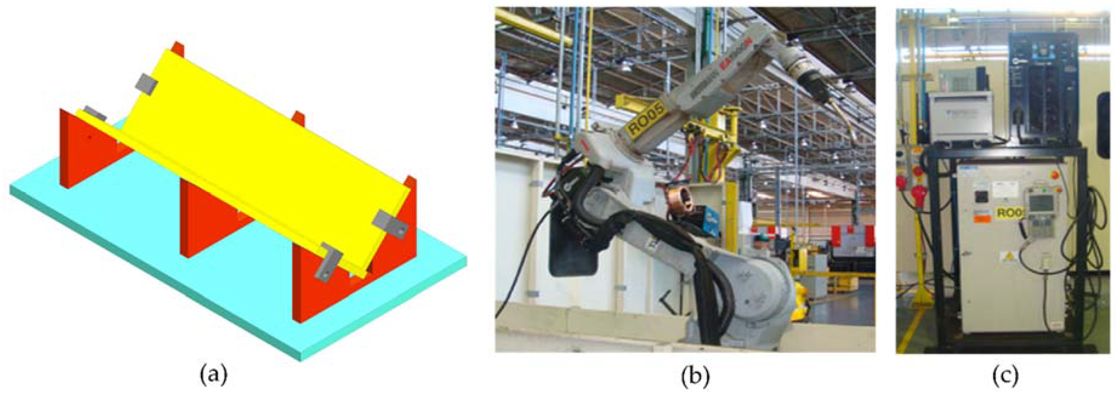
2. Materials and Methods

The material chosen for the production of samples was LNE 700 high-strength steel, which is manufactured by USIMINAS using a hot lamination process. The 50 × 100 × 4.5 mm samples were produced using a LASER cutting process. The chemical composition of the base material, which is shown in Table 1, was obtained using a mass spectrometer (Model PDA-700, Shimadzu, Kyoto, Japan). The filler metal used was OK AristorodTM 79 (ESAB, London, UK) wire with a diameter of 1.0 mm. Table 2 shows its chemical composition of wire.
Figure 1a shows the device used to fix the plates during welding. The welding was performed using a Yaskama MA model 1900 robot with six degrees of freedom, as shown in Figure 1b. The shielding gas used was a mixture comprising argon (82%) and CO2 (18%). The power supply used for welding was Auto-Axcess 450, which is able to detect short-circuits during welding, has a pulsed electric arc and spray, and an electric current output of 450 ampères (Figure 1c).
The plates were positioned on the device to form a T-joint and the weld beads were made in a flat position, in which the torch of the robot was positioned at 45° between the two plates at a distance of 20 mm, as shown in Figure 2. The metal transfer mode used was pulsed electric arc welding, in which the equipment generated two electric current levels. The weld bead was applied on only one side of the weld joint.
The specimens were characterized in accordance with the following quality criteria: microhardness, heat-affected zone (HAZ), convex fillet (convexity), length of the theoretical throat and leg, as shown in Figure 3b.
To prepare the test specimen and to analyze the microhardness of welded joints, the following items of equipment were used: a cutting Machine, model Discoton-2; a Polishing machine, model Ecomet-4; an Olympus BX51M microscope with 100× amplification; a Microhardness Tester, model Shimadzu, with a load capacity of 0.015 up to 1000 g. All test specimens were sectioned, sanded, polished and chemically attacked with nital (10%) to reveal the microstructure of the material. Each test specimen was sectioned into three regions, thus adding to the level of confidence in the measurements taken.
The microhardness was measured under a load of 1 kg each 0.7 mm distance, thus creating a profile of microhardness. The measurement of microhardness was according to a specific standard [24], which specifies that for plates that are more than 4 mm thick in the T-joints, the microhardness must be measured within 2 mm from the edge, thus using a distance of 1 mm for taking measurements. The microhardness was measured in a sectioned region of each test specimen. Figure 3a shows the location of the microhardness measurement points and the dimensions used.
The analysis of HAZ and its geometry consists of capturing a larger image of the region of the welded joint with the aid of a microscope. ImageJ software was used to take the measurements of the image. Subsequently, the average values obtained in the three regions of each test specimen were calculated.

Design of Experiments

To carry out the welding assays, an experimental design was compiled using the Taguchi method. Three levels for each parameter–factor (voltage, welding speed and wire feed speed) were used. The process parameters were defined in accordance with the greatest influence on quality criteria, which are often adjusted in accordance with the type of material to be welded. The levels were chosen previously by the means of welding assays. An L9 Taguchi orthogonal array was used, which provided an interaction between the factors and the respective levels, thereby allowing for a consistent analysis of the quality criteria (Table 3). Three specimens were made for each order. Therefore, there was a total of twenty-seven test specimens.
Variance analysis (ANOVA) was performed to determine the influence of the factors on the output variables, in which the influences of factors that had a p-value equal to or less than 0.05 (considered to be a critical value) were considered reliable, which indicates a degree of confidence equal to or above 95% in relation to what is being affirmed. The results were validated by performing the welding process again with the factors that were considered ideal. The signal/noise (S/N) ratio was used to optimize the responses of the variables.

3. Results and Discussion

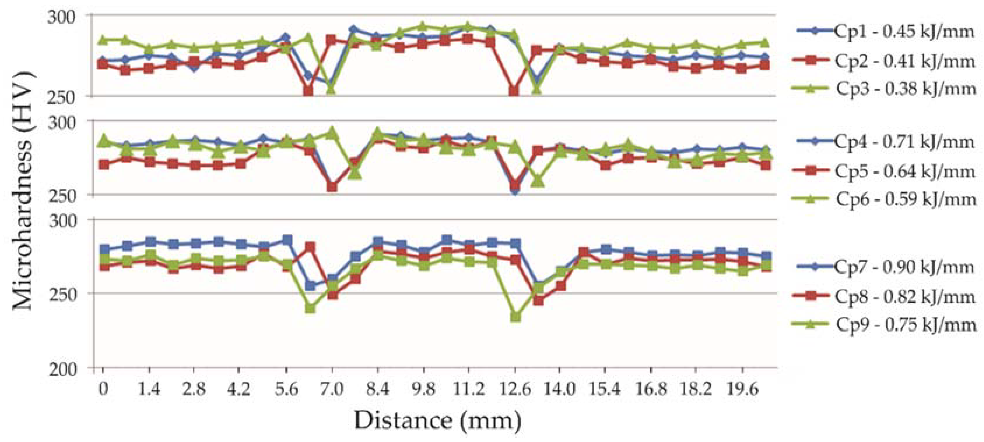
3.1. Profile of Microhardness

The microhardness profile found in each test specimen showed an average hardness of 270 Vickers for the base metal and 255 Vickers for the HAZ. These values are consistent with the pattern of hardness for the type of material analyzed [25]. Figure 4 shows the different microhardness profiles for the nine orders of the specimen tested, i.e., the nine different welding powers.
Note that the hardness changed mainly in the HAZ, i.e., the hardness decreased, thus confirming the data collected in the review of the literature [25,26,27]. Also, note that increasing the welding energy, the regions with the lowest hardness increased and the use of filler metal with a similar yield stress to that of the base metal provided a constant microhardness profile without major variations.

3.2. Heat-Affected Zone-HAZ

By analyzing the HAZ, it was found that the thermal influence of the welding process on the material is significant. This influence can be seen in the HAZ due to the change in the microstructure of the material, whereas, whenever the voltage was increased, the HAZ width increased, thus forming thermally affected areas, as shown in Figure 5.
As there was a confidence level of 95%, it can be said that the three factors examined had a significant influence on the HAZ dimensions (p-value < 0.05). Similarly, the variables that had the greatest influence on the HAZ are determined by the F-values, i.e., the higher the F-value the greater its influence on the HAZ. Thus, the most influential factors, respectively, were welding speed, voltage and wire feed speed (Table 4).
For a better analysis of the effects of process parameters on the HAZ, charts were plotted, which made it possible to show the influence of these parameters on the effect of the criterion under examination. Figure 6a shows how the size of the HAZ is affected by the voltage, where the HAZ increased as the voltage increased.
HAZ as a function of welding speed shows that on average, the HAZ decreases when the speed of welding increases (Figure 6b). Thus, for the smallest HAZ, the welding speed 10 mm/s presents the best results.
The HAZ, as a function of the wire speed rate, showed less influence among the three varying process parameters, as shown in Figure 6c. The HAZ increased when the wire speed rate increased. Thus, the smallest HAZ can be obtained when the wire speed rate of 12.6 m/min is used.
As to the signal-to-noise ratio for the HAZ, it can be said that with a 95% confidence level, the three process parameters (voltage, welding speed and the wire speed rate) are factors of influence on the HAZ, which is why as to the S/N ratio, the smaller the better, as can be verified in Figure 6d. The highest quality in the result of the welding in the HAZ, i.e., the smallest HAZ can be obtained when a voltage of 23.5 V, a welding speed of 10 mm/s and a wire speed rate of 12.6 m/min are chosen.
A new test specimen for validation was used with the following parameters: the voltage of 23.5 V, welding speed of 10 mm/s and wire speed rate of 12.6 m/min. This test specimen showed a smaller HAZ, this being 22 mm², thus providing proof that the relationship expressed by the signal-to-noise ratio shows that smaller is better.

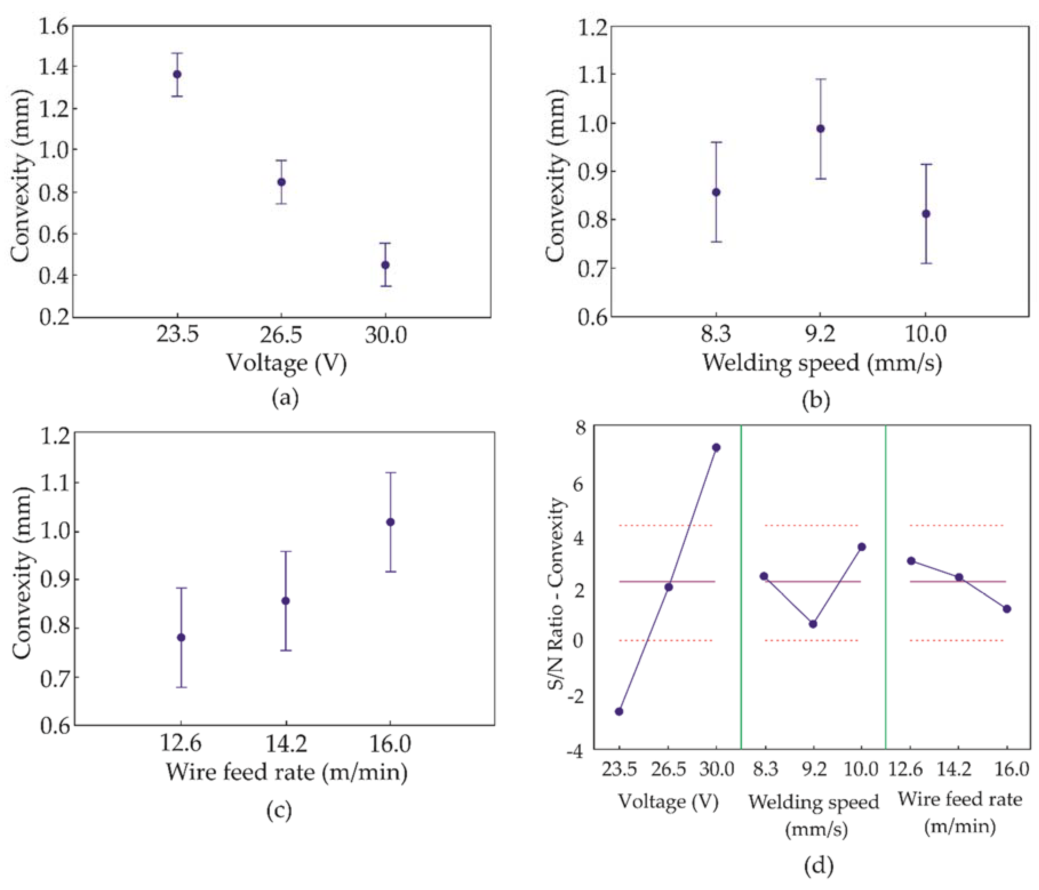
3.3. Convexity, Length of the Theoretical Throat and Leg

The convexity showed significant variations of values between 0.39 and 1.54 mm. The ANOVA showed a result with a 95% confidence level for the voltage factor and welding speed on the convexity. This analysis showed that the probability p-value was less than 0.05 and, consequently, it can be said that these variables had a significant influence on the convexity. Similarly, the variables that had the greatest influence on convexity were determined by the F-values, i.e., the higher the F-value, the greater its influence on the criterion of convexity. Thus, the most influential factors were voltage, welding speed and wire speed rate, respectively, as can be verified from Table 5.
For a better analysis of the effects of the process parameters on the convexity, charts were plotted, which made it possible to show the influence of these parameters on the convexity.
Figure 7a presents the results of convexity as a function of voltage. The considerable influence of the voltage influence on the results of convexity can be seen. The convexity, on average, decreases when the voltage increases. Thus, a voltage of 30 V presents better results for less convexity. The convexity as a function of welding speed showed influence; however, it was a less significant one, as shown in Figure 7b. The values show that best results for convexity will be obtained when a welding speed of 10 mm/s is used. By analyzing the convexity as a function of the wire speed rate, it can be verified that the relationship is less decisive for the convexity results, as seen in Figure 7c. On average, the convexity increased when the wire speed rate and the electric current were increased. However, for the best results of the convexity, it is advisable to use a wire speed rate of 12.6 m/min.
As to the signal-to-noise ratio for the convexity, it can be said with a 95% confidence level that the voltage and the welding speed were the most influential factors for convexity, and thus that the smaller the S/N, the better, as shown in Figure 7d. The highest quality as a result of the welding with the convexity will be obtained at a voltage of 30 V, a welding speed of 10 mm/s and a wire speed rate of 12.6 m/min. The new test specimen for validation of the convexity used the following parameters: a voltage of 30 V, a welding speed of 10 mm/s and a wire speed rate of 12.6 m/min. The test specimen for validation showed the convexity was small, thereby providing proof of the relationship expressed by the signal-to-noise ratio, thus proving that the smaller the convexity, the better. The results showed a convexity value of 0.38 mm (Figure 8a).
Analysis of the theoretical throat revealed that the values found were between 3.5 and 4.7 mm. These values match the acceptable results for the welding performed. Analysis of the leg length showed that leg length 1 had values of between 4.9 and 7.2 mm while leg length 2 had values ranging from 4.8 to 6.2 mm. All values represented acceptable leg sizes. The lowest values found for the theoretical throat (3.52 mm) and leg length (3.87 mm and 3.95 mm) are given in Figure 8b.

4. Conclusions

In accordance with the characterization of the robotized GMAW welding of the LNE 700 high-strength steel, the following conclusions can be drawn:
  • the best parameters for welding LNE 700 high-strength steel that meets each quality criterion (HAZ and convexity) were determined. The Taguchi method proved to be an important tool for the experimental design as well as for statistical analysis that focuses on validating a manufacturing process;
  • the analysis proved the influence of process parameters on the quality of robotized GMAW welding of LNE 700 high-strength steel;
  • the microhardness profile presented values that satisfy the type of material studied. The use of filler metal with characteristics of flow stress similar to that of the base metal led to little variation, on average, in the hardness of the welded joint. The different process parameters used provided variations in the size of the region of lowest hardness for the HAZ, it is noticeable that the higher the voltage, the greater the greater areas of least hardness. The welding power values in each test specimen were different. However, discontinuities resulting from these different welding powers were not observed;
  • the three process parameters (voltage, welding speed and wire speed rate) showed a significant influence, there being a 95% confidence level in the result for the HAZ.
  • A strong relation of convexity with the voltage was detected, i.e., a greater voltage resulted in less convexity of the welded joint. Of the three process parameters (voltage, welding speed and speed of the wire), the voltage and the welding speed showed that they had a significant influence, there being a 95% confidence level in the results. An observation can be made regarding the convexity, i.e., if the objective of this paper had been to create metallic walls, according to Lu et al. [28], the ideal would be to choose the greater the better in the Taguchi method, so it would be possible to determine the best welding parameters to achieve the maximum size of convexity.

Author Contributions

D.R.B. and C.P.L. performed the tests, analyzed the results and wrote the paper. V.d.J.A. assisted in the analysis of the results. R.T.L. and A.D.M. planned the study, assisted in the analysis of the results and with writing the paper.

Funding

This research received no external funding.

Acknowledgments

The author (R.T.L.) is grateful to the Fundação Meridional for financial support.

Conflicts of Interest

The authors declare no conflict of interest.

References

  1. Soares, G.G. Caracterização da Junta Dissimilar em Solda de Materiais do Tipo Estrutural Arbl; Universidade de Passo Fundo: Passo Fundo, RS, Brazil, 2015. [Google Scholar]
  2. Mvola, B.; Kah, P.; Martikainen, J.; Suoranta, R. State-of-the-art of advanced gas metal arc welding processes: Dissimilar metal welding. Proc. Inst. Mech. Eng. Part B J. Eng. Manuf. 2015, 229, 1694–1710. [Google Scholar] [CrossRef]
  3. Urbikain, G.; Perez, J.M.; López de Lacalle, L.N.; Andueza, A. Combination of friction drilling and form tapping processes on dissimilar materials for making nutless joints. Proc. Inst. Mech. Eng. Part B J. Eng. Manuf. 2018, 232, 1007–1020. [Google Scholar] [CrossRef]
  4. Koo, J.; Luton, M.; Bangaru, N.; Petkovic, R.; Fairchild, D.; Petersen, C.; Asahi, H.; Hara, T.; Terada, Y.; Sugiyama, M. Metallurgical design of ultra high-strength steels for gas pipelines. Int. J. Offshore Polar Eng. 2004, 14, 10–18. [Google Scholar]
  5. Meyer, L.; Strassburger, C.; Schneider, C. Effect and present application of the microalloying elements niobium, vanadium, titanium, zirconium, and boron in HSLA steels. In Proceedings of the HSLA Steels, Beijing, China, 4–8 November 1985. [Google Scholar]
  6. Tamehiro, H.; Murata, M.; Habu, R.; Nagumo, M. Optimum microalloying of niobium and boron in HSLA steel for thermomechanical processing. Trans. Iron Steel Inst. Jpn. 1987, 27, 120–129. [Google Scholar] [CrossRef]
  7. Lee, S.G.; Lee, D.H.; Sohn, S.S.; Kim, W.G.; Um, K.-K.; Kim, K.-S.; Lee, S. Effects of Ni and Mn addition on critical crack tip opening displacement (CTOD) of weld-simulated heat-affected zones of three high-strength low-alloy (HSLA) steels. Mater. Sci. Eng. A 2017, 697, 55–65. [Google Scholar] [CrossRef]
  8. Sharma, S.K.; Maheshwari, S. A review on welding of high strength oil and gas pipeline steels. J. Nat. Gas Sci. Eng. 2017, 38, 203–217. [Google Scholar] [CrossRef]
  9. Boyer, R.; Cotton, J.; Mohaghegh, M.; Schafrik, R. Materials considerations for aerospace applications. MRS Bull. 2015, 40, 1055–1066. [Google Scholar] [CrossRef] [Green Version]
  10. Hermenegildo, T.F.; Santos, T.F.; Torres, E.A.; Afonso, C.R.; Ramirez, A.J. Microstructural evolution of HSLA ISO 3183 X80M (API 5L X80) friction stir welded joints. Met. Mater. Int. 2018, 24, 1120–1132. [Google Scholar] [CrossRef]
  11. Gao, Z.; Ding, Q.; Yang, H.; Li, J.; Zhu, G.; Liu, Z. Development of Nb-Bearing High Strength Steel Plates for 150,000 m3 Oil Storage Tank. In Proceedings of the ASME 2017 Pressure Vessels and Piping Conference, Waikoloa, HI, USA, 16–20 July 2017; American Society of Mechanical Engineers: New York, NY, USA, 2017. [Google Scholar]
  12. Yang, T.C.; Huang, C.Y.; Cheng, T.C.; Yu, C.; Shiue, R.K. Two high strength low alloy steels for offshore application. In Advanced Materials Research; Trans Tech Publications: Zurich, Switzerland, 2014; pp. 1312–1316. [Google Scholar]
  13. Ferreira, D.P.; Santos, C.S.; Jesus, A.C. Estudo dos aços de alta resistência baixa liga (ARBL) para aplicação em blindagem de carros fortes. Anais da SEMCITEC-Semana de Ciência, Tecnologia, Inovação e Desenvolvimento de Guarulhos 2018, 1. Available online: http://revista.ifspguarulhos.edu.br/index.php/semcitec/article/download/30/24 (accessed on 22 September 2018).
  14. Colaço, R. Steel for civil construction. In Materials for Construction and Civil Engineering; Springer: Berlin, Germany, 2015; pp. 273–302. [Google Scholar]
  15. USIMINAS. Certificado de Inspeção; USIMINAS: São Paulo, Brazil, 2011. [Google Scholar]
  16. SSAB. Sheet Steel Joining Handbook. Joining of High Strength Steels; Tunnplat AB: New York, NY, USA, 2004. [Google Scholar]
  17. Machado, I.G. Falhas de estruturas de aço soldadas devido à reduzida ductilidade. Soldag. Inspeção 2013, 18, 391–403. [Google Scholar] [CrossRef]
  18. Andia, J.; de Souza, L.F.G.; Bott, I. Microstructural and mechanical properties of the intercritically reheated coarse grained heat affected zone (ICCGHAZ) of an API 5L X80 pipeline steel. In Materials Science Forum; Trans Tech Publications: Zurich, Switzerland, 2014; pp. 657–662. [Google Scholar]
  19. Kapustka, N.; Conrardy, C.; Babu, S.; Albright, C. Effect of GMAW process and material conditions on DP 780 and TRIP 780 welds. Weld. J. N. Y. 2008, 87, 135–148. [Google Scholar]
  20. Hochhauser, F.; Ernst, W.; Rauch, R.; Vallant, R.; Enzinger, N. Influence of the soft zone on the strength of welded modern HSLA steels. Weld. World 2012, 56, 77–85. [Google Scholar] [CrossRef]
  21. Górka, J. Influence of the maximum temperature of the thermal cycle on the properties and structure of the HAZ of steel S700MC. IOSR J. Eng. 2013, 3, 22–28. [Google Scholar] [CrossRef]
  22. Gliner, R. Welding of advanced high-strength sheet steels. Weld. Int. 2011, 25, 389–396. [Google Scholar] [CrossRef]
  23. Haupt, W.; Riffel, K.; Israel, C.; Silva, R.; Reguly, A. Effect of wire electrode and shielding gas compositions on the mechanical properties of DOMEX 700 steel welded by the GMAW-P process. J. Braz. Soc. Mech. Sci. Eng. 2018, 40, 174. [Google Scholar] [CrossRef]
  24. DIN. Hardness Testing of Welds in Metallic Materials—Hardness Test on arc Welded Joints; En 1043-1; Deutsches Institut fur Normung E.V.: Berlin, Germany, 1996. [Google Scholar]
  25. Tunnplat, S. Sheet Steel Joining Handbook: Joining of High Strength Steels; SSAB Tunnplat AB: Stockholm, Sweden, 2004. [Google Scholar]
  26. Musgen, B. High strength quenched and tempered steels-production, properties and applications. Met. Constr. 1985, 17, 495–500. [Google Scholar]
  27. Lazić, V.; Aleksandrović, S.; Nikolić, R.; Prokić-Cvetković, R.; Popović, O.; Milosavljević, D.; Čukić, R. Estimates of weldability and selection of the optimal procedure and technology for welding of high strength steels. Procedia Eng. 2012, 40, 310–315. [Google Scholar] [CrossRef]
  28. Lu, X.; Zhou, Y.; Xing, X.; Shao, L.; Yang, Q.; Gao, S. Open-source wire and arc additive manufacturing system: Formability, microstructures, and mechanical properties. Int. J. Adv. Manuf. Technol. 2017, 93, 2145–2154. [Google Scholar] [CrossRef]
Figure 1. (a) Device for positioning plates; (b) Yaskama MA 1900 robot and (c) Auto-Axcess 450 power supply.
Jmmp 02 00070 g001
Figure 2. The position of the welding torch in relation to the axis of the weld bead.
Jmmp 02 00070 g002
Figure 3. (a) Specifications for measuring microhardness, (b) convexity, sizes of the legs and the theoretical throat.
Jmmp 02 00070 g003
Figure 4. Microhardness profile for different welding powers.
Jmmp 02 00070 g004
Figure 5. (a) Macrograph of the weld joint, (b) microstructure of the weld metal, (c) microstructure of the growth zone of the grain growth, (d) microstructure, of the refining zone of the grain, and (e) microstructure of the base metal.
Jmmp 02 00070 g005
Figure 6. (a) HAZ as a function of voltage; (b) HAZ as a function of welding speed; (c) HAZ as a function of wire feed rate; and (d) signal-to-noise ratio (smaller is better) for the HAZ.
Jmmp 02 00070 g006
Figure 7. (a) Convexity as a function of voltage; (b) convexity depending on the welding speed; (c) convexity as a function of the wire speed rate; and (d) the S/N ratio of the width of the convexity for the factors analyzed.
Jmmp 02 00070 g007
Figure 8. (a) Test specimen for convexity validation and (b) lowest values found for the theoretical throat and the length of length.
Jmmp 02 00070 g008
Table 1. The chemical composition of LNE 700 steel.
Chemical ElementsCSiMnPSAlCuNbVTi
%0.10.031.530.020.0030.0580.020.040.0070.108
Chemical ElementsCrNiMoSnNBCaSbPbCe
%0.430.020.020.0020.00370.00010.00120.010.0030.45
Table 2. Chemical composition of OK AristorodTM 79 (ESAB) wire.
Chemical ElementsCSiMnCrNiMo
%0.10.81.90.42.10.6
Table 3. Experimental array with the order of assays and their levels.
OrderVoltage (V)Welding Speed (mm/s)Wire Speed (m/min)Welding Energy (kJ/mm)
123.58.312.60.45
223.59.214.20.41
323.510.016.00.38
426.58.314.20.71
526.59.216.00.64
626.510.012.60.59
7308.316.00.90
8309.212.60.82
93010.014.20.75
Table 4. ANOVA for the heat-affected zone.
SourceSum of SquaresDegree of FreedomAverages of the SquaresF-Valuep-Value
Voltage189.4450294.72252409.11710.0000
Welding speed27.1017213.5508758.52770.0000
Wire speed15.213027.6065032.85330.0000
Residue4.6306200.23153--
Table 5. ANOVA for the convexity.
SourceSum of SquaresDegree of FreedomAverages of the SquaresF-Valuep-Value
Voltage434.31062217.155363.105670.0000
Welding speed37.9313218.96575.511450.0124
Wire speed14.438927.21952.097980.1489
Residue68.8227203.4411--

