
A Review on the Processing of Aero-Turbine Blade Using 3D Print Techniques

 ,
,  and
and 
Abstract
:1. Introduction
2. Current Scenario of Turbine Blade
3. Design Development of Turbine Blade from Traditional to 3D Print Mode
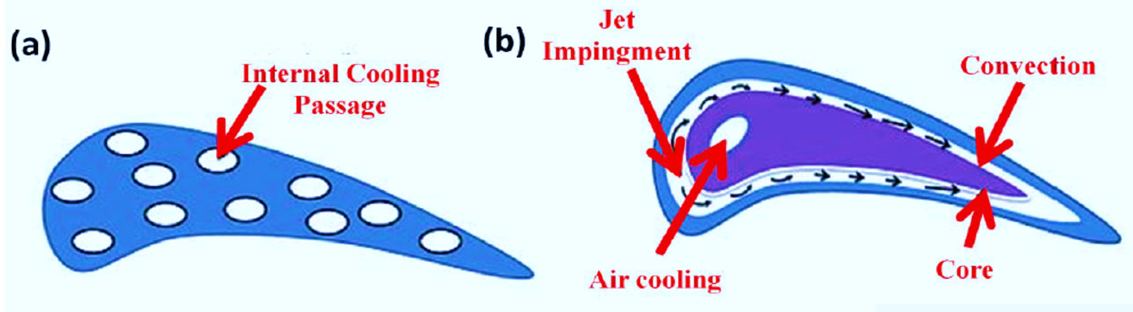
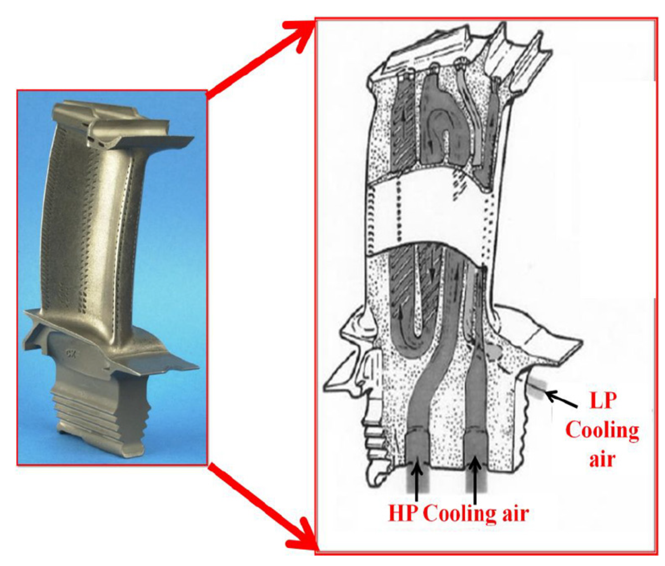
- Internal cooling design: The convection cooling design uses cooling air that passes through the internal ducts of the blade, as shown in Figure 3a. Heat is extracted from the turbine blades via the convection process and the air moving through the blade also helps to decrease the blade temperature. To make this technique work effectively, the parts should contain large surface areas. The path of the air moving through the blade tends to be coiled spirally and complete with small fins. The shape of the passages inside the blade can be elliptical. Air travels from the hub through the tip of the blades to cool the blade design. However, the hot air outside the blade is relatively hot as it flows through the cooling channels and merges with the primary flow at the blade tip. Different convection cooling methods are available such as impinging design, which hits the inner surface with high-speed cooling air jets. Continuous air circulation improves the heat transfer rate compared to convection heating. The first set of blades in the turbine section experiences the highest load on the turbine. Therefore, the maximum temperature is observed at the leading edge of the blade and hence experience the thermal load. The central chords of the blades also use the technique of impact cooling (Figure 3b). The blades are hollow with internal cores and channels. The cooling air enters the leading edge and cools the fins that pass through the trailing edge [20].
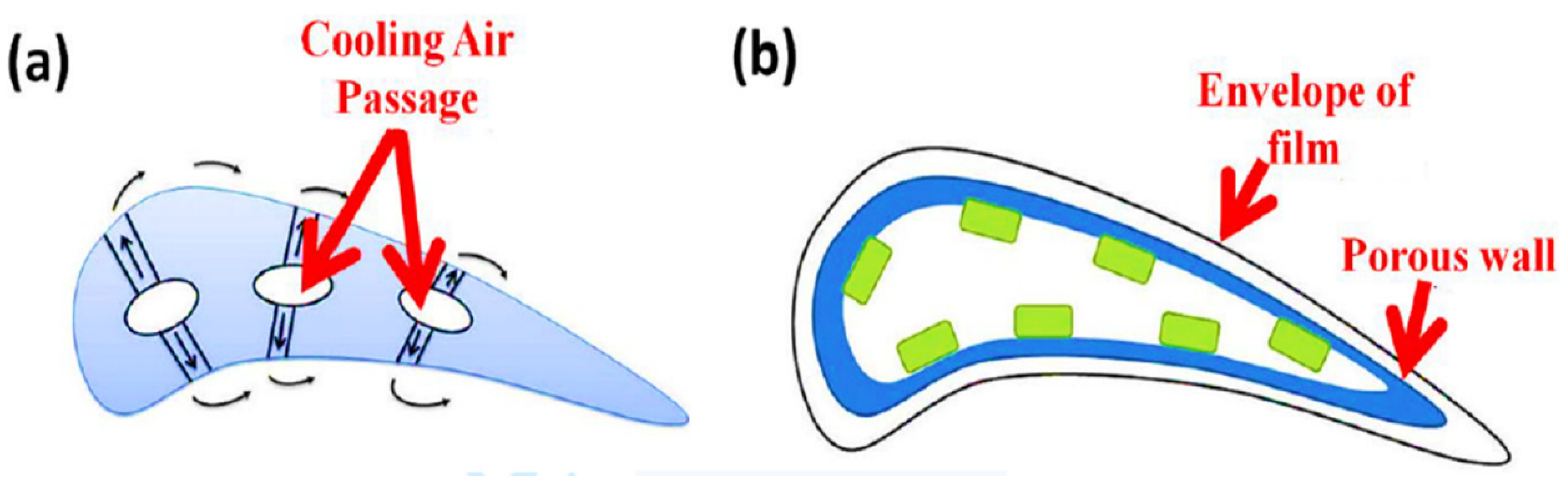
- External cooling: In addition to the cooling with techniques such as convection and impact, external cooling, also referred to as film cooling, is adapted. Air circulates through the small holes in the blade to decrease the temperature of the blade. The cooling air forms a thin layer on the outer surfaces of the blade. The heat energy transferred to the blade can exceed the melting point of the blade material of the blade whereas the heat extraction process improves the material ability and enhances the TET of the blade. Figure 4a shows the design of the film cooling turbine blade. The cooling efficiency is considered as the ability of the cooling system to extract heat from the blade surface. This efficiency depends on various parameters such as the flow of the coolant through the structure and the injection, velocity, momentum ratios, and density of the coolant. The injection geometry parameters have holes and slot geometry with injection angles. In the 1970s, the United States Air Force program funded several projects to develop the turbine blade for the military aircraft engine, which included both convection cooling and film cooling, which has become common for modern turbine blades [22]. Isentropic efficiency, air compression, and cooling systems increase the complexity of engine cooling. All of these factors contribute to the increase in overall engine performance as the TET continues to increase. Recently, researchers have recommended the application of a plasma actuator to cool the film [23]. In the design of effusion cooling, the surface of the blade is fabricated with materials consisting of porous structures that improve the surface temperature. The cooling air flows through the porous holes in the structure to generate a boundary layer on the blade surface. As the coolant circulates over the surface of the entire blade, uniform cooling is achieved. Figure 4b shows the design of the cooling of the blades by effusion. In the finned cooling design, the film-cooled trailing edge improves heat extraction of the entire blade. The design consists of pinholes and substructures to improve the cooling rate. Heat transfer occurs through the array of pin holes as well as the side walls. As the coolant flows through the fins at high speed, the separation of flows due to the fins produces wakes. Heat transfer depends on the type of fin pin used and the spacing between the fins. Transpiration cooling also generates a thin film of cooling air on the blade, which makes it similar to film cooling, but differs in that the air is ‘leaked’ using a porous shell rather than being injected through the holes. At higher temperatures, these cooling methods become effective because they form an even blanket of cool air on the blade. Transpiration-cooled blades are generally made with pores and strong structures. Therefore, the air must circulate through the various internal channels present in the structure before passing through the porous shells and finally cooling the turbine blade. The cooling of the film, the amount of air pushed through the blades, and the efficiency of the engine are related in such a way that the optimization is necessary to maximize the performance of the engine [20].
4. AM Techniques for the Fabrication of Turbine Blades
4.1. Selective Laser Sintering (SLS) as an Initial Powder Bed Fusion Process
4.2. Selective Laser Melting (SLM)/Direct Metal Laser Sintering (DMLS) as Currently Used for Metals
4.3. Electron Beam Melting
4.4. Binder Jetting Process
4.5. Laser Cladding
4.6. Laser Engineering Net Shape
4.7. Electron Beam Free-Form Fabrication
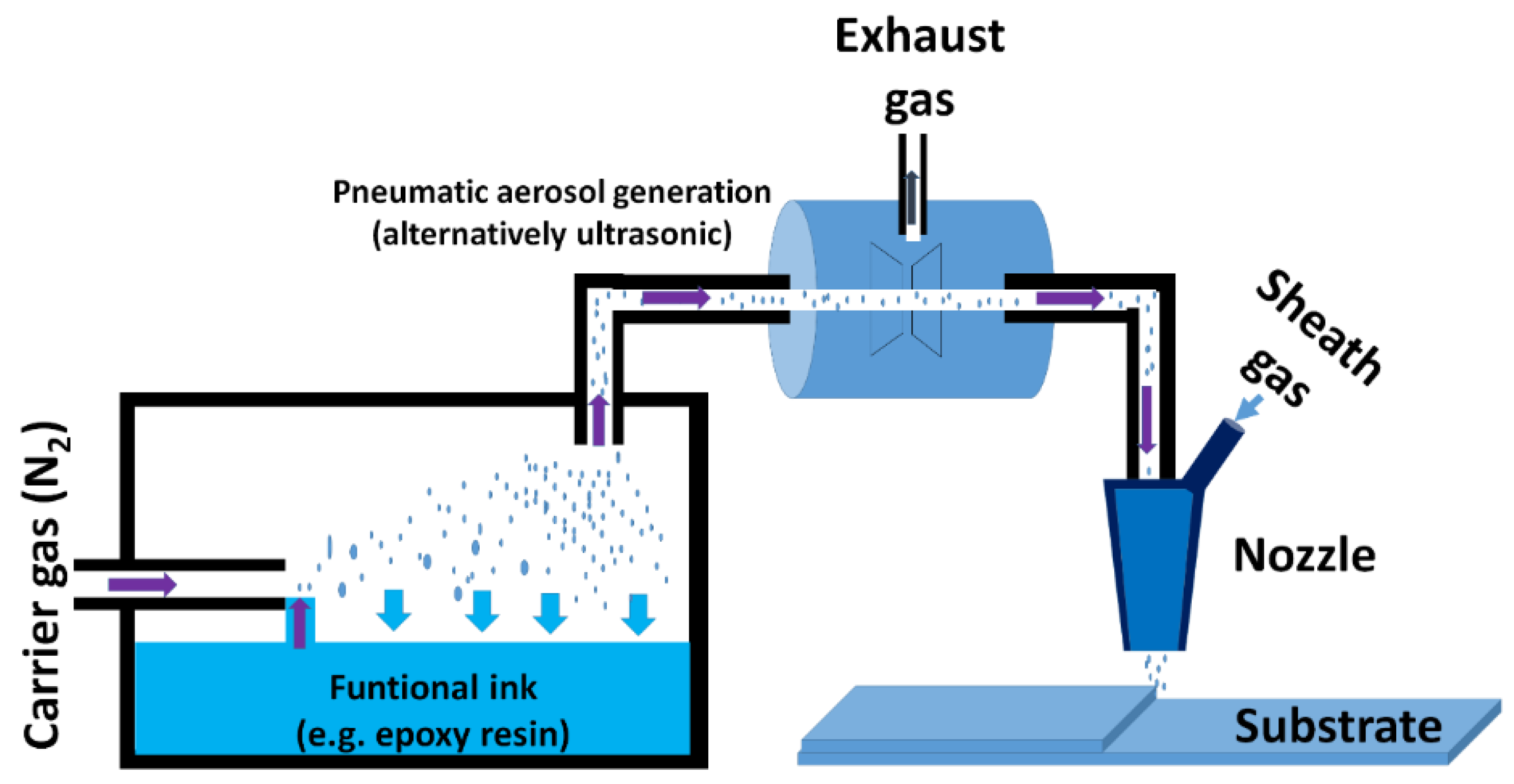
4.8. Aerosol Jet Process
5. Processing Parameters
5.1. Particle Size and Shape of Powder That to Be Printed
5.2. Powder Bed Density
5.3. Residual Stresses
5.4. Porosity
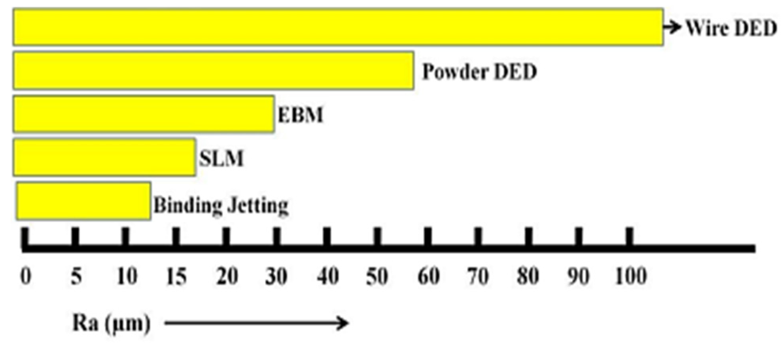
5.5. Roughness
- (a)
- Core process resolution and precision: Resolution and accuracy are key parameters for 3D printing of the turbine blade and also to determine surface roughness. This is because 3D printing creates parts layer-by-layer and the resolution can be classified according to the axis. In the XY axes, the resolution depends on the processes that take place specifically in production [137]. For example, in PBF techniques, the diameter of the laser or electron beam is a measure of the resolution of the process while in binder jetting, the resolution of the jetting process is achieved in dots per inch (DPI). In the case of the DED technique, the width of the spheres deposited is the measure of the resolution. In the Z direction, the resolution for most processes is associated with the layer thickness or the slice thickness. The XY and Z resolutions of typical 3D printing processes are given in Table 3 [138]. When designing the component, viz., turbine blade, using AM, it is better for the designer to have an understanding of the part orientation and the build direction, so that they can decide the optimal number of features that will be subjected to high forces oriented in the X–Y plane.
- (b)
- Material feedstock-type, size, and quality: Parameters such as the morphology of the powder particles (size and shape) and the quality of the powder present in the raw material influence the surface roughness. In PBF and binder jetting processes, the physical properties of the powder grains such as the size and shape that are attached to the exterior side of the finished part have an impact on the roughness. Generally, raw powder materials can differ in shapes from spherical shapes with sizes as low as 5 μm, and unevenly shaped up to 120 μm particles. Here, the quality of the powder is a crucial parameter in processing as low-level powder can lead to undesirable mechanisms such as clumping, which prevents the powder from properly flowing and distributing, resulting in increased surface roughness [140].
- (c)
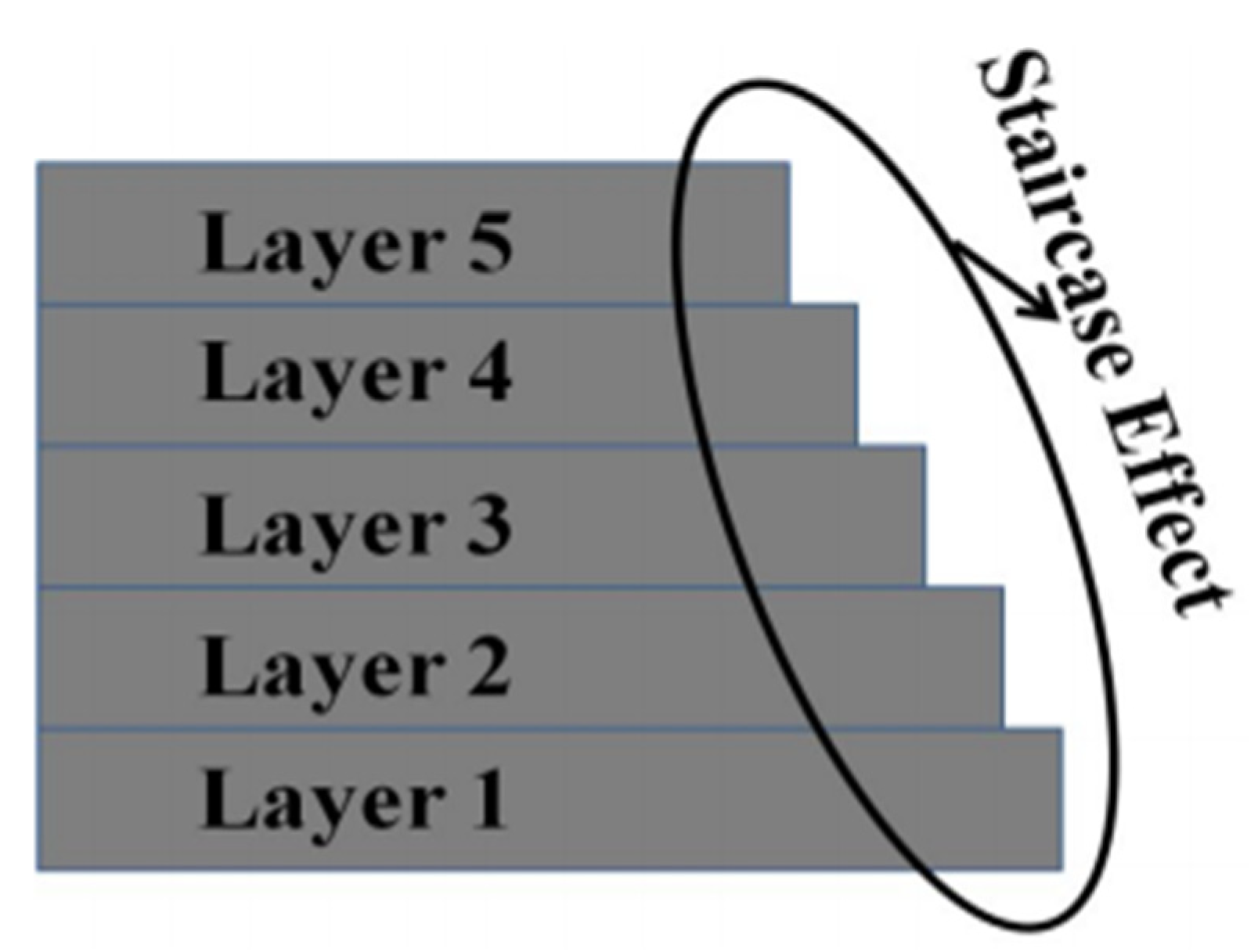
- Print orientation: The surface quality of blade fabricated using AM process is directly related to print orientation. The print orientation of the blade’s surface plays a crucial role [141]. The total printing height of the product is determined by the print orientation. As the height increases, the number of layers to be printed increases, which in turn increases the total vertical surfaces to be printed. Thus the staircase effect by every layer along the Z direction increases eventually, resulting in the poor surface finish of the blade.
- (d)
- Support structure: The use of support material is essential in most AM technologies. Supports are provided for the overhanging features of the part. Supports also assist in anchoring certain features to the build plate. Support material also takes part in heat transfer. The amount of support structures depends on the part orientation. Support material greatly affects surface quality and post-processing cost. These support structures are not part of the actual product and hence they are removed during post-processing. The physical removal of these support structures may lead to residual features left on the part, which also contributes to the surface roughness [142].
- (e)
- Other key processing parameters: The various processing parameters that can alter the surface roughness of the parts include power input, print speed, build geometry, and cooling rates. To obtain the highest surface quality, these parameters must be optimized as per the specific AM process [143].
6. Defect Formation, Cracking Mechanisms, and Strength
7. Microstructural Anisotropy
8. Summary and Future Perspective
Author Contributions
Funding
Data Availability Statement
Conflicts of Interest
References
- Verde, C.; Sánchez-Parra, M. Monitorability Analysis for a Gas Turbine Using Structural Analysis. In Fault Detection, Supervision and Safety of Technical Processes 2006; Elsevier: Amsterdam, The Netherlands, 2007; pp. 675–680. [Google Scholar]
- Pattnaik, S.; Karunakar, D.B.; Jha, P.K. Developments in Investment Casting Process—A Review. J. Mater. Process. Technol. 2012, 212, 2332–2348. [Google Scholar] [CrossRef]
- EOS Turbine Blade. Available online: https://www.eos.info/en/3d-printing-examples-applications/production-and-industry/turbomachinery-turbines (accessed on 15 November 2021).
- Jiang, R.; Kleer, R.; Piller, F.T. Predicting the Future of Additive Manufacturing: A Delphi Study on Economic and Societal Implications of 3D Printing for 2030. Technol. Forecast. Soc. Chang. 2017, 117, 84–97. [Google Scholar] [CrossRef]
- Richardson, J.J.; Cui, J.; Björnmalm, M.; Braunger, J.A.; Ejima, H.; Caruso, F. Innovation in Layer-by-Layer Assembly. Chem. Rev. 2016, 116, 14828–14867. [Google Scholar] [CrossRef] [PubMed] [Green Version]
- Turbine Blade 1c. Available online: https://www.wikiwand.com/en/Turbine_blade (accessed on 15 November 2021).
- Magerramova, L.; Vasilyev, B.; Kinzburskiy, V. Novel Designs of Turbine Blades for Additive Manufacturing. In Proceedings of the ASME Turbo Expo 2016: Turbomachinery Technical Conference and Exposition, Seoul, Korea, 13–17 June 2016. [Google Scholar]
- Additive Manufacturing Market. Available online: https://www.researchcosmos.com/reports/additive-manufacturing-market/1170635782 (accessed on 15 November 2021).
- GE Aviation Invests in Widespread Rollout of GE Additive Arcam EBM Technology to Support GE9X Blade Production. Available online: https://www.ge.com/additive/press-releases/ge-aviation-invests-widespread-rollout-ge-additive-arcam-ebm-technology-support-ge9x (accessed on 15 November 2021).
- Angel, N.M.; Basak, A. On the Fabrication of Metallic Single Crystal Turbine Blades with a Commentary on Repair via Additive Manufacturing. J. Manuf. Mater. Process. 2020, 4, 101. [Google Scholar] [CrossRef]
- Lattime, S.; Steinetz, B. Turbine Engine Clearance Control Systems: Current Practices and Future Directions. In Proceedings of the 38th AIAA/ASME/SAE/ASEE Joint Propulsion Conference & Exhibit, Indianapolis, Indiana, 7–10 July 2002. [Google Scholar]
- Chatterjee, B.; Bhowmik, S. Chapter 9—Evolution of Material Selection in Commercial Aviation Industry—A Review. In Sustainable Engineering Products and Manufacturing Technologies; Academic Press: Cambridge, MA, USA, 2019; pp. 199–219. ISBN 978-0-12-816564-5. [Google Scholar] [CrossRef]
- GE9X Commercial Aircraft Engine|GE Aviation. Available online: https://www.geaviation.com/commercial/engines/ge9x-commercial-aircraft-engine (accessed on 15 November 2021).
- Aircraft Engine Blades Market—Growth, Trends, Covid-19 Impact, and Forecasts (2022–2027). Available online: https://www.mordorintelligence.com/industry-reports/aircraft-engine-blades-market (accessed on 15 November 2021).
- M88—Proven Performance and Reliability. Available online: https://www.safran-aircraft-engines.com/military-engines/training-and-combat-aircraft/m88 (accessed on 15 November 2021).
- Mertens, A.I.; Delahaye, J.; Lecomte-Beckers, J. Fusion-Based Additive Manufacturing for Processing Aluminum Alloys: State-of-the-Art and Challenges. Adv. Eng. Mater. 2017, 19, 1700003. [Google Scholar] [CrossRef]
- Singh, K. Advanced Materials for Land Based Gas Turbines. Trans. Indian Inst. Met. 2014, 67, 601–615. [Google Scholar] [CrossRef]
- Langston, L.S. Powering Out of Trouble. Mech. Eng. 2013, 135, 36–41. [Google Scholar] [CrossRef] [Green Version]
- Wang, T. 15—The Gas and Steam Turbines and Combined Cycle in IGCC Systems. In Integrated Gasification Combined Cycle (IGCC) Technologies; Elsevier: Amsterdam, The Netherlands, 2017; pp. 497–640. ISBN 978-0-08-100167-7. [Google Scholar] [CrossRef]
- Chyu, M.K.; Siw, S.C. Recent Advances of Internal Cooling Techniques for Gas Turbine Airfoils. J. Therm. Sci. Eng. Appl. 2013, 5, 2–12. [Google Scholar] [CrossRef]
- Turbine Blade Internal Cooling. Available online: https://www.wikiwand.com/en/Turbine_blade (accessed on 15 November 2021).
- Koff, B.L. Gas Turbine Technology Evolution: A Designers Perspective. J. Propuls. Power 2004, 20, 577–595. [Google Scholar] [CrossRef]
- Dai, S.; Xiao, Y.; He, L.; Jin, T.; Hou, P.; Zhang, Q.; Zhao, Z. Computational Study of Plasma Actuator on Film Cooling Performance for Different Shaped Holes. AIP Adv. 2015, 5, 67104. [Google Scholar] [CrossRef] [Green Version]
- Turbine Blade External Cooling. Available online: https://en.wikipedia.org/wiki/Turbine_blade (accessed on 15 November 2021).
- Blading, W.C. Wariable Camber Blading. Patent U.S. 3042371, 3 July 1962. [Google Scholar]
- Suter, D.P. Blading for Rotors of Axial Compressors 1969. Patent DE1903642A1, 8 June 1969. [Google Scholar]
- Ziegler, G.D.I. Twisted and Tapered Blade for Axial Turbo Machinery. Patent DE2144600A1, 15 March 1973. [Google Scholar]
- Brown, R. Guide Vanes for Supersonic Turbine Blades 1974. Patent U.S. 3837761A, 24 September 1974. [Google Scholar]
- Bliss, D.B. Method of and Apparatus for Preventing Leading Edge Shocks and Shock-Related Noise in Transonic and Supersonic Rotor Blades and the Like 1976. Patent U.S. 3989406A, 2 November 1976. [Google Scholar]
- Kazin, S.B.; Matta, R.K. Curved Blade Turbomachinery Noise Reduction 1978. Patent U.S. 4131387A, 26 December 1978. [Google Scholar]
- Zipps, R.H.; Rynaski, C.H.; Fulton, G.B. Fan Rotor Blades of Turbofan Engines 1986. Patent U.S. 4621979A, 11 November 1986. [Google Scholar]
- Application filed by United Technologies Corp Rotor Assembly for Gas Turbine Engine 1982. Patent IL67806A, 31 October 1986.
- Martin, J.R. Bowed Turbine Blade 1987. Patent U.S. 4682935A, 28 July 1987. [Google Scholar]
- Braddy, B.T.; Eldrid, S.Q. Turbine Blade with Tip Vent 1988. Patent U.S. 4761116A, 2 August 1988. [Google Scholar]
- Brent, A. Gregory Curvilinear Turbine Airfoi 1986. Patent U.S. 4826400A, 2 May 1989. [Google Scholar]
- Wertz, T.A.; Saltzman, G.A.; Friedman, I.L. Turbine Blade with Restored Tip 1989. Patent U.S. 4808055A, 28 February 1989. [Google Scholar]
- Mank, H. Tran Free Standing Blade for Use in Low Pressure Steam Turbine 1991. Patent U.S. 5017091A, 21 May 1991. [Google Scholar]
- John, W. Magowan Coolable Rotor Blade Structure 1994. Patent WO1994012390A2, 9 June 1994. [Google Scholar]
- Jurek, F.; Daniel, R. Cornell Light Weight Steam Turbine Blade 1993. Patent U.S. 5352092A, 4 October 1994. [Google Scholar]
- Lee, C.P.; Pietraszkiewicz, E.F.; Prakash, C.; Zerkle, R.D. Turbine Blade Having Tip Slot 1996. Patent U.S. 5503527A, 2 April 1996. [Google Scholar]
- Thomas, A.; Frank, W.; HuberRobert, R.; SellersFriedrich, O. Soechting Cooled Blades for a Gas Turbine Engine 1990. Patent AU684039B1, 4 December 1997. [Google Scholar]
- Norbert, H.; Reinhard, D. Niehuis Turbomachine Blade 1997. Patent EP0798447B1, 5 September 2001. [Google Scholar]
- Auxier, T.; Hall, K.; Mcclelland, R. Cooled Blades for a Gas Turbine Engine 1988. Patent AU684037B1, 4 December 1997. [Google Scholar]
- Take Sato, Y.Y. Axial Flow Turbine Vane Device and Axial Flow Turbine 1990. Patent JP2753382B2, 20 May 1998. [Google Scholar]
- Pepperman, L.; Pepperman, B. Gas Turbine Blade with Cooled Platform 1998. Patent EP0777818B1, 14 October 1998. [Google Scholar]
- Rowlands, P.A. Swept Fan Blade 2000. Patent U.S. 6071077A, 6 June 2000. [Google Scholar]
- Wood, P.; Decker, J.; Steinmetz, T.; Mielke, M.; Seitzer, K. Narrow Waist Vane 2001. Patent U.S. 6312219B1, 6 November 2001. [Google Scholar]
- Bauer, K. Helicopter Rotor Blade with a Movable Flap 2001. Patent U.S. 6168379B1, 2 January 2001. [Google Scholar]
- Chandraker, A. Three Dimensional Blade 2004. Patent U.S. 20030086788A1, 23 March 2004. [Google Scholar]
- Ganshaw, T.J. Stress Relieved Blade Support 2001. Patent U.S. 6183202B1, 6 February 2001. [Google Scholar]
- Goodman, P.J. Tip Sealing for a Turbine Rotor Blade 2006. Patent GB2409006B, 17 May 2006. [Google Scholar]
- Bagai, A. Rotor Blade Pitch Control Assembly 2006. Patent U.S. 6984109B2, 10 January 2006. [Google Scholar]
- Richard, S.; Chiurato, R. Turbine Blade Pocket Shroud 2001. Patent CN100351495C, 28 November 2007. [Google Scholar]
- Takahashi, C.M. Transonic Blade 2010. Patent U.S. 20100215503A1, 23 April 2013. [Google Scholar]
- Sun, F.; Chaudhry, Z.; Yeh, J.; O'Callaghan, M.; Jonsson, U.; Wake, B.; Dold, R. Hybrid Actuator for Helicopter Rotor Blade Control Flaps 2008. Patent U.S. 7762770B2, 27 July 2010. [Google Scholar]
- Wood, P.; Falk, E.; Dailey, L. Advanced Booster Rotor Blade 2011. Patent U.S. 7967571B2, 28 June 2011. [Google Scholar]
- Kilaras, M.S. Vortex Dynamics Turbine 2011. Patent U.S. 20110229321A1, 22 September 2011. [Google Scholar]
- Fred, T.; Willett, J. Turbines and Turbine Blade Winglets 2013. Patent U.S. 8414265B2, 9 April 2013. [Google Scholar]
- Suciu, G.L.; James, D.H.; Gary, M.S. Reverse Cavity Blade for a Gas Turbine Engine 2010. Patent U.S. 8740567B2, 3 June 2014. [Google Scholar]
- Penny, C.; Gustafson, R. Turbomachine Blade with Tip Flare 2013. Patent U.S. 8894376B2, 25 November 2014. [Google Scholar]
- Hoebel, M.; Ambrosy, G.; Reinert, F.; Barril, S. Wear-Resistant and Oxidation-Resistant Turbine Blade 2015. Patent EP2316988B1, 8 July 2015. [Google Scholar]
- Chouhan, R.; Bommanakatte, H.; Soni, S.; Jayana, S.G.; Kareff, S.A. Fillet for Use with a Turbine Rotor Blade Tip Shroud 2014. Patent U.S. 9322282B2, 26 April 2016. [Google Scholar]
- Wunderer, R. Blade Cascade and Turbomachine 2013. Patent U.S. 9404368B2, 2 August 2016. [Google Scholar]
- Craig, K.; Joseph, B.; Alisha, K. Turbine Blade with Contoured Platform 2011. Patent CA2771349C, 5 September 2017. [Google Scholar]
- Jones, M.A.; Brozyna, L.L. Turbine Blade Centroid Shifting Method and System 2017. Patent U.S. 9995144B2, 12 June 2018. [Google Scholar]
- Man, M.D.; Delabrierel, P.; Coudert, J.-A.M.; Destouchesd, M. Optimized Aerodynamic Profile for a Turbine Vane, in Particular for a Nozzle of the Second Stage of a Turbine 2018. Patent U.S. 10443392B2, 15 October 2019. [Google Scholar]
- Hamed, A.A.; Tabakoff, W.; Rivir, R.B.; Das, K.; Arora, P. Turbine Blade Surface Deterioration by Erosion. J. Turbomach. 2004, 127, 445–452. [Google Scholar] [CrossRef]
- Ruffles, P.C. Aero Engines of the Future. Aeronaut. J. 2003, 107, 307–321. [Google Scholar] [CrossRef]
- Wei, Z.; Qiao, W.; Shi, P.; Chen, P.; Zhao, L. Tip-Leakage Flow Loss Reduction in a Two-Stage Turbine Using Axisymmetric-Casing Contouring. Chin. J. Aeronaut. 2014, 27, 1111–1121. [Google Scholar] [CrossRef] [Green Version]
- Turbine Cooling Trent 500. Available online: https://aerospaceengineeringblog.com/turbine-cooling/ (accessed on 15 November 2021).
- Pal, A.; Bertoldi, K.; Pham, M.Q.; Schaenzer, M.; Gross, A.J. Optimal Turbine Blade Design Enabled by Auxetic Honeycomb. Smart Mater. Struct. 2020, 29, 125004. [Google Scholar] [CrossRef]
- Garg, S. Aircraft Turbine Engine Control Research at NASA Glenn Research Center. J. Aerosp. Eng. 2013, 26, 422–438. [Google Scholar] [CrossRef] [Green Version]
- Xue, S.; Ng, W.F. Turbine Blade Tip External Cooling Technologies. Aerospace 2018, 5, 90. [Google Scholar] [CrossRef]
- Schubel, P.J.; Crossley, R.J. Wind Turbine Blade Design. Energies 2012, 5, 3425–3449. [Google Scholar] [CrossRef] [Green Version]
- Matsuura, K.M.K. 3D Free Shaping Method and 3D Free Shaping Apparatus. Patent JP4223637B2, 12 February 2009. [Google Scholar]
- Jennings, C. Gas Turbine Engine Component Having Engineered Vascular Structure. Patent EP3179042B1, 4 March 2020. [Google Scholar]
- Xu, J. Method for Forming Components Using Additive Manufacturing and Re-Melt. Patent U.S. 20160339516A1, 1 August 2017. [Google Scholar]
- Garner, C. Turbine Blade Having an Additive Manufacturing Trailing Edge. Patent U.S. 20190063229A1, 2 March 2021. [Google Scholar]
- Tapia, L.; Halfmann, S.; Harman, S.A. Turbine Rotor Assemblies with Improved Slot Cavities. Patent EP2896786B1, 13 March 2019. [Google Scholar]
- Thomas, S.; Mironets, A.; Staroselsky, B.S.; Thomas, M. Airfoil, and Method for Manufacturing the Same. Patent U.S. 20160369634A1, 26 November 2019. [Google Scholar]
- Tracy, H.; Dominic, M.; Benjamin, F. Additively Manufactured Core. Patent 10525525, 7 January 2020. [Google Scholar]
- Kruth, J.P.; Wang, X.; Laoui, T.; Froyen, L. Lasers and Materials in Selective Laser Sintering. Assem. Autom. 2003, 23, 357–371. [Google Scholar] [CrossRef]
- Yap, C.Y.; Chua, C.K.; Dong, Z.L.; Liu, Z.H.; Zhang, D.Q.; Loh, L.E.; Sing, S.L. Review of Selective Laser Melting: Materials and Applications. Appl. Phys. Rev. 2015, 2, 041101. [Google Scholar] [CrossRef]
- Additive Manufacturing: Siemens Uses Innovative Technology to Produce Gas Turbines. Available online: https://press.siemens.com/global/en/feature/additive-manufacturing-siemens-uses-innovative-technology-produce-gas-turbines (accessed on 15 November 2021).
- Simens Ni Alloy Based Turbine Blade. Available online: https://blogs.sw.siemens.com/nx-design/3d-printing-in-nx/ (accessed on 15 November 2021).
- Galati, M.; Iuliano, L. A Literature Review of Powder-Based Electron Beam Melting Focusing on Numerical Simulations. Addit. Manuf. 2018, 19, 1–20. [Google Scholar] [CrossRef]
- Rafi, H.K.; Karthik, N.V.; Gong, H.; Starr, T.L.; Stucker, B.E. Microstructures and Mechanical Properties of Ti6Al4V Parts Fabricated by Selective Laser Melting and Electron Beam Melting. J. Mater. Eng. Perform. 2013, 22, 3872–3883. [Google Scholar] [CrossRef]
- EBM Made Turbine Blade by GE. Available online: https://www.ge.com/additive/stories/additive-at-scale-avio-aero (accessed on 15 November 2021).
- Kellner, T. Avio Aero, a General Electric (GE) Aviation EBM Turbine Blade. Available online: https://www.ge.com/news/reports/future-manufacturing-take-look-inside-factory-3d-printing-jet-engine-parts (accessed on 15 November 2021).
- Yadav, P.; Fu, Z.; Knorr, M.; Travitzky, N. Binder Jetting 3D Printing of Titanium Aluminides Based Materials: A Feasibility Study. Adv. Eng. Mater. 2020, 22, 2000408. [Google Scholar] [CrossRef]
- Mostafaei, A.; Stevens, E.L.; Hughes, E.T.; Biery, S.D.; Hilla, C.; Chmielus, M. Powder Bed Binder Jet Printed Alloy 625: Densification, Microstructure and Mechanical Properties. Mater. Des. 2016, 108, 126–135. [Google Scholar] [CrossRef] [Green Version]
- Popov, V.V.; Grilli, M.L.; Koptyug, A.; Jaworska, L.; Katz-Demyanetz, A.; Klobčar, D.; Balos, S.; Postolnyi, B.O.; Goel, S. Powder Bed Fusion Additive Manufacturing Using Critical Raw Materials: A Review. Materials 2021, 14, 909. [Google Scholar] [CrossRef]
- Varotsis, A.B. Introduction to Binder Jetting 3D Printing- 3D HUBS. Available online: https://www.hubs.com/knowledge-base/introduction-binder-jetting-3d-printing/ (accessed on 15 November 2021).
- Everett, H. Exone to Develop High-Strength Steel Alloy for U.S. Air Force—3d Printing Industry. Available online: https://3dprintingindustry.com/news/exone-to-develop-high-strength-steel-alloy-for-u-s-air-force-177992/ (accessed on 15 November 2021).
- Fang, X.; Du, J.; Wei, Z.; He, P.; Bai, H.; Wang, X.; Lu, B. An Investigation on Effects of Process Parameters in Fused-Coating Based Metal Additive Manufacturing. J. Manuf. Process. 2017, 28, 383–389. [Google Scholar] [CrossRef]
- Eboo, G.M.; Blake, A.G. Laser Cladding of Gas Turbine Components. In Proceedings of the ASME 1986 International Gas Turbine Conference and Exhibit, Dusseldorf, Germany, 8–12 June 1986. [Google Scholar] [CrossRef] [Green Version]
- Alimardani, M.; Fallah, V.; Khajepour, A.; Toyserkani, E. The Effect of Localized Dynamic Surface Preheating in Laser Cladding of Stellite 1. Surf. Coatings Technol. 2010, 204, 3911–3919. [Google Scholar] [CrossRef]
- Izadi, M.; Farzaneh, A.; Mohammed, M.; Gibson, I.; Rolfe, B. A Review of Laser Engineered Net Shaping (LENS) Build and Process Parameters of Metallic Parts. Rapid Prototyp. J. 2020, 26, 1059–1078. [Google Scholar] [CrossRef]
- Vaezi, M.; Chianrabutra, S.; Mellor, B.; Yang, S. Multiple Material Additive Manufacturing—Part 1: A Review. Virtual Phys. Prototyp. 2013, 8, 19–50. [Google Scholar] [CrossRef]
- Albuquerque Optomec Customers Surpass 10 Million Turbine Blade Repairs. Available online: https://optomec.com/optomec-customers-surpass-10-million-turbine-blade-repairs/ (accessed on 15 November 2021).
- Carlota, V. Optomec Customers Have Repaired More than 10 Million Turbine Blades- Optomec. Available online: https://www.3dnatives.com/en/optomec-customer-surpass-10-million-turbine-blade-repairs-260820204/#! (accessed on 15 November 2021).
- Majumdar, T.; Eisenstein, N.; Frith, J.E.; Cox, S.C.; Birbilis, N. Additive Manufacturing of Titanium Alloys for Orthopedic Applications: A Materials Science Viewpoint. Adv. Eng. Mater. 2018, 20, 1800172. [Google Scholar] [CrossRef]
- William, J.; Seufzer Robert, A. Hafley Height Control and Deposition Measurement for the Electron Beam Free Form Fabrication (EBF3) Process. Patent 9764415, 19 September 2017. [Google Scholar]
- Electron-Beam Freeform Fabrication (EBF3): Technology and Application. Available online: https://3d-expo.ru/en/article/proizvodstvo-elektronno-luchevoy-plavkoy-ebf-tehnologiya-i-primenenie-80098 (accessed on 15 November 2021).
- AMFG Application Spotlight: 3D Printing for Turbine Parts. Available online: https://amfg.ai/2020/02/06/application-spotlight-3d-printing-for-turbine-parts/ (accessed on 15 November 2021).
- Reitberger, T.; Hoerber, J.; Schramm, R.; Sennefelder, S.; Franke, J. Aerosol Jet® Printing of Optical Waveguides. In Proceedings of the 2015 38th International Spring Seminar on Electronics Technology (ISSE), Eger, Hungary, 6–10 May 2015. [Google Scholar] [CrossRef]
- Garboczi, E.J.; Hrabe, N. Particle Shape and Size Analysis for Metal Powders Used for Additive Manufacturing: Technique Description and Application to Two Gas-Atomized and Plasma-Atomized Ti64 Powders. Addit. Manuf. 2020, 31, 100965. [Google Scholar] [CrossRef]
- Strondl, A.; Lyckfeldt, O.; Brodin, H.; Ackelid, U. Characterization and Control of Powder Properties for Additive Manufacturing. JOM 2015, 67, 549–554. [Google Scholar] [CrossRef]
- Bai, Y.; Wagner, G.; Williams, C.B. Effect of Particle Size Distribution on Powder Packing and Sintering in Binder Jetting Additive Manufacturing of Metals. J. Manuf. Sci. Eng. 2017, 139, 081019. [Google Scholar] [CrossRef] [Green Version]
- Brika, S.E.; Letenneur, M.; Dion, C.A.; Brailovski, V. Influence of Particle Morphology and Size Distribution on the Powder Flowability and Laser Powder Bed Fusion Manufacturability of Ti-6Al-4V Alloy. Addit. Manuf. 2020, 31, 1–37. [Google Scholar] [CrossRef]
- Kiani, P.; Scipioni Bertoli, U.; Dupuy, A.D.; Ma, K.; Schoenung, J.M. A Statistical Analysis of Powder Flowability in Metal Additive Manufacturing. Adv. Eng. Mater. 2020, 22, 2000022. [Google Scholar] [CrossRef]
- Ali, U.; Mahmoodkhani, Y.; Imani Shahabad, S.; Esmaeilizadeh, R.; Liravi, F.; Sheydaeian, E.; Huang, K.Y.; Marzbanrad, E.; Vlasea, M.; Toyserkani, E. On the Measurement of Relative Powder-Bed Compaction Density in Powder-Bed Additive Manufacturing Processes. Mater. Des. 2018, 155, 495–501. [Google Scholar] [CrossRef]
- Nguyen, Q.B.; Nai, M.L.S.; Zhu, Z.; Sun, C.-N.; Wei, J.; Zhou, W. Characteristics of Inconel Powders for Powder-Bed Additive Manufacturing. Engineering 2017, 3, 695–700. [Google Scholar] [CrossRef]
- Spierings, A.B.; Schneider, M.; Eggenberger, R. Comparison of Density Measurement Techniques for Additive Manufactured Metallic Parts. Rapid Prototyp. J. 2011, 17, 380–386. [Google Scholar] [CrossRef]
- Kamath, C.; El-dasher, B.; Gallegos, G.F.; King, W.E.; Sisto, A. Density of Additively-Manufactured, 316L SS Parts Using Laser Powder-Bed Fusion at Powers up to 400 W. Int. J. Adv. Manuf. Technol. 2014, 74, 65–78. [Google Scholar] [CrossRef] [Green Version]
- Vickers, N.J. Animal Communication: When I’m Calling You, Will You Answer Too? Curr. Biol. 2017, 27, R713–R715. [Google Scholar] [CrossRef] [PubMed]
- Micromeritics AccuPyc II. Available online: https://www.micromeritics.com/accupyc-ii/ (accessed on 15 November 2021).
- Micromeritics GeoPyc 1365. Available online: https://www.micromeritics.com/micromeritics-geopyc-1365-envelope-density-analyzer/ (accessed on 15 November 2021).
- Mussatto, A.; Groarke, R.; O’Neill, A.; Obeidi, M.A.; Delaure, Y.; Brabazon, D. Influences of Powder Morphology and Spreading Parameters on the Powder Bed Topography Uniformity in Powder Bed Fusion Metal Additive Manufacturing. Addit. Manuf. 2021, 38, 101807. [Google Scholar] [CrossRef]
- Maamoun, A.H.; Xue, Y.F.; Elbestawi, M.A.; Veldhuis, S.C. Effect of Selective Laser Melting Process Parameters on the Quality of Al Alloy Parts: Powder Characterization, Density, Surface Roughness, and Dimensional Accuracy. Materials 2018, 11, 12. [Google Scholar] [CrossRef] [PubMed] [Green Version]
- Khairallah, S.A.; Anderson, A.T.; Rubenchik, A.; King, W.E. Laser Powder-Bed Fusion Additive Manufacturing: Physics of Complex Melt Flow and Formation Mechanisms of Pores, Spatter, and Denudation Zones. Acta Mater. 2016, 108, 36–45. [Google Scholar] [CrossRef] [Green Version]
- Li, C.; Liu, Z.Y.; Fang, X.Y.; Guo, Y.B. Residual Stress in Metal Additive Manufacturing. Procedia CIRP 2018, 71, 348–353. [Google Scholar] [CrossRef]
- Megahed, M.; Mindt, H.-W.; N’Dri, N.; Duan, H.; Desmaison, O. Metal Additive-Manufacturing Process and Residual Stress Modeling. Integr. Mater. Manuf. Innov. 2016, 5, 61–93. [Google Scholar] [CrossRef] [Green Version]
- Genzel, C.; Denks, I.A.; Gibmeier, J.; Klaus, M.; Wagener, G. The Materials Science Synchrotron Beamline EDDI for Energy-Dispersive Diffraction Analysis. Nucl. Instrum. Methods Phys. Res. Sect. A Accel. Spectrometers Detect. Assoc. Equip. 2007, 578, 23–33. [Google Scholar] [CrossRef]
- Mishurova, T.; Artzt, K.; Haubrich, J.; Requena, G.; Bruno, G. Exploring the Correlation between Subsurface Residual Stresses and Manufacturing Parameters in Laser Powder Bed Fused Ti-6Al-4V. Metals 2019, 9, 261. [Google Scholar] [CrossRef] [Green Version]
- Nadammal, N.; Mishurova, T.; Fritsch, T.; Serrano-Munoz, I.; Kromm, A.; Haberland, C.; Portella, P.D.; Bruno, G. Critical Role of Scan Strategies on the Development of Microstructure, Texture, and Residual Stresses during Laser Powder Bed Fusion Additive Manufacturing. Addit. Manuf. 2021, 38, 1–33. [Google Scholar] [CrossRef]
- Mukherjee, T.; Zhang, W.; DebRoy, T. An Improved Prediction of Residual Stresses and Distortion in Additive Manufacturing. Comput. Mater. Sci. 2017, 126, 360–372. [Google Scholar] [CrossRef] [Green Version]
- Szost, B.A.; Terzi, S.; Martina, F.; Boisselier, D.; Prytuliak, A.; Pirling, T.; Hofmann, M.; Jarvis, D.J. A Comparative Study of Additive Manufacturing Techniques: Residual Stress and Microstructural Analysis of CLAD and WAAM Printed Ti–6Al–4V Components. Mater. Des. 2016, 89, 559–567. [Google Scholar] [CrossRef] [Green Version]
- Vastola, G.; Zhang, G.; Pei, Q.X.; Zhang, Y.-W. Controlling of Residual Stress in Additive Manufacturing of Ti6Al4V by Finite Element Modeling. Addit. Manuf. 2016, 12, 231–239. [Google Scholar] [CrossRef]
- DePond, P.J.; Guss, G.; Ly, S.; Calta, N.P.; Deane, D.; Khairallah, S.; Matthews, M.J. In Situ Measurements of Layer Roughness during Laser Powder Bed Fusion Additive Manufacturing Using Low Coherence Scanning Interferometry. Mater. Des. 2018, 154, 347–359. [Google Scholar] [CrossRef]
- Tapia, G.; Elwany, A.H.; Sang, H. Prediction of Porosity in Metal-Based Additive Manufacturing Using Spatial Gaussian Process Models. Addit. Manuf. 2016, 12, 282–290. [Google Scholar] [CrossRef]
- Baturynska, I. Statistical Analysis of Dimensional Accuracy in Additive Manufacturing Considering STL Model Properties. Int. J. Adv. Manuf. Technol. 2018, 97, 2835–2849. [Google Scholar] [CrossRef]
- Huang, S.H.; Liu, P.; Mokasdar, A.; Hou, L. Additive Manufacturing and Its Societal Impact: A Literature Review. Int. J. Adv. Manuf. Technol. 2013, 67, 1191–1203. [Google Scholar] [CrossRef]
- Delgado, J.; Ciurana, J.; Rodríguez, C.A. Influence of Process Parameters on Part Quality and Mechanical Properties for DMLS and SLM with Iron-Based Materials. Int. J. Adv. Manuf. Technol. 2012, 60, 601–610. [Google Scholar] [CrossRef]
- Jamshidinia, M.; Kovacevic, R. The Influence of Heat Accumulation on the Surface Roughness in Powder-Bed Additive Manufacturing. Surf. Topogr. Metrol. Prop. 2015, 3, 014003. [Google Scholar] [CrossRef]
- Li, Z.; Zhang, Z.; Shi, J.; Wu, D. Prediction of Surface Roughness in Extrusion-Based Additive Manufacturing with Machine Learning. Robot. Comput. Integr. Manuf. 2019, 57, 488–495. [Google Scholar] [CrossRef]
- Hirsch, M.; Patel, R.; Li, W.; Guan, G.; Leach, R.K.; Sharples, S.D.; Clare, A.T. Assessing the Capability of In-Situ Nondestructive Analysis during Layer Based Additive Manufacture. Addit. Manuf. 2017, 13, 135–142. [Google Scholar] [CrossRef] [Green Version]
- Popov, D.; Maltsev, E.; Fryazinov, O.; Pasko, A.; Akhatov, I. Efficient Contouring of Functionally Represented Objects for Additive Manufacturing. Comput. Des. 2020, 129, 102917. [Google Scholar] [CrossRef]
- Huckstepp, A. Surface Roughness—A Guide to Metal Additive Manufacturing by Digital Alloys. Available online: https://manufactur3dmag.com/surface-roughness-a-guide-to-metal-additive-manufacturing-by-digital-alloys/ (accessed on 15 November 2021).
- Bourell, D.; Kruth, J.P.; Leu, M.; Levy, G.; Rosen, D.; Beese, A.M.; Clare, A. Materials for Additive Manufacturing. CIRP Ann. 2017, 66, 659–681. [Google Scholar] [CrossRef]
- Chowdhury, S.; Mhapsekar, K.; Anand, S. Part Build Orientation Optimization and Neural Network-Based Geometry Compensation for Additive Manufacturing Process. J. Manuf. Sci. Eng. 2017, 140, 031009. [Google Scholar] [CrossRef]
- Higueros, E.; Roe, E.; Granell, E.; Baselga, E. Sturge-Weber Syndrome: A Review. Actas Dermosifiliogr. 2017, 108, 407–417. [Google Scholar] [CrossRef]
- DebRoy, T.; Wei, H.L.; Zuback, J.S.; Mukherjee, T.; Elmer, J.W.; Milewski, J.O.; Beese, A.M.; Wilson-Heid, A.; De, A.; Zhang, W. Additive Manufacturing of Metallic Components—Process, Structure and Properties. Prog. Mater. Sci. 2018, 92, 112–224. [Google Scholar] [CrossRef]
- Mukherjee, T.; Wei, H.L.; De, A.; DebRoy, T. Heat and Fluid Flow in Additive Manufacturing—Part II: Powder Bed Fusion of Stainless Steel, and Titanium, Nickel and Aluminum Base Alloys. Comput. Mater. Sci. 2018, 150, 369–380. [Google Scholar] [CrossRef]
- Knapp, G.L.; Mukherjee, T.; Zuback, J.S.; Wei, H.L.; Palmer, T.A.; De, A.; DebRoy, T. Building Blocks for a Digital Twin of Additive Manufacturing. Acta Mater. 2017, 135, 390–399. [Google Scholar] [CrossRef]
- Yin, S.; Cavaliere, P.; Aldwell, B.; Jenkins, R.; Liao, H.; Li, W.; Lupoi, R. Cold Spray Additive Manufacturing and Repair: Fundamentals and Applications. Addit. Manuf. 2018, 21, 628–650. [Google Scholar] [CrossRef]
- Jiang, Z.; Tao, W.; Yu, K.; Tan, C.; Chen, Y.; Li, L.; Li, Z. Comparative Study on Fiber Laser Welding of GH3535 Superalloy in Continuous and Pulsed Waves. Mater. Des. 2016, 110, 728–739. [Google Scholar] [CrossRef]
- Lalehpour, A.; Barari, A. A More Accurate Analytical Formulation of Surface Roughness in Layer-Based Additive Manufacturing to Enhance the Product’s Precision. Int. J. Adv. Manuf. Technol. 2018, 96, 3793–3804. [Google Scholar] [CrossRef]
- Yampolskiy, M.; King, W.E.; Gatlin, J.; Belikovetsky, S.; Brown, A.; Skjellum, A.; Elovici, Y. Security of Additive Manufacturing: Attack Taxonomy and Survey. Addit. Manuf. 2018, 21, 431–457. [Google Scholar] [CrossRef]
- Gao, W.; Zhang, Y.; Ramanujan, D.; Ramani, K.; Chen, Y.; Williams, C.B.; Wang, C.C.L.; Shin, Y.C.; Zhang, S.; Zavattieri, P.D. The Status, Challenges, and Future of Additive Manufacturing in Engineering. Comput. Des. 2015, 69, 65–89. [Google Scholar] [CrossRef]
- Mahmood, M.A.; Visan, A.I.; Ristoscu, C.; Mihailescu, I.N. Artificial Neural Network Algorithms for 3D Printing. Materials 2021, 14, 163. [Google Scholar] [CrossRef]
- Leung, C.L.A.; Marussi, S.; Atwood, R.C.; Towrie, M.; Withers, P.J.; Lee, P.D. In Situ X-Ray Imaging of Defect and Molten Pool Dynamics in Laser Additive Manufacturing. Nat. Commun. 2018, 9, 1–9. [Google Scholar] [CrossRef] [Green Version]
- Lee, Y.S.; Kirka, M.M.; Ferguson, J.; Paquit, V.C. Correlations of Cracking with Scan Strategy and Build Geometry in Electron Beam Powder Bed Additive Manufacturing. Addit. Manuf. 2020, 32, 101031. [Google Scholar] [CrossRef]
- Attallah, M.M.; Jennings, R.; Wang, X.; Carter, L.N. Additive Manufacturing of Ni-Based Superalloys: The Outstanding Issues. MRS Bull. 2016, 41, 758–764. [Google Scholar] [CrossRef]
- Herzog, D.; Seyda, V.; Wycisk, E.; Emmelmann, C. Additive Manufacturing of Metals. Acta Mater. 2016, 117, 371–392. [Google Scholar] [CrossRef]
- Brandl, E. Microstructural and Mechanical Properties of Additive Manufactured Titanium (Ti-6Al-4V) Using Wire: Evaluation with Respect to Additive Processes Using Powder and Aerospace Material Specifications; Shaker Verlag GmbH: Aachen, Germany, 2011. [Google Scholar]
- Carlton, H.D.; Haboub, A.; Gallegos, G.F.; Parkinson, D.Y.; MacDowell, A.A. Damage Evolution and Failure Mechanisms in Additively Manufactured Stainless Steel. Mater. Sci. Eng. A 2016, 651, 406–414. [Google Scholar] [CrossRef] [Green Version]
- Wycisk, E.; Solbach, A.; Siddique, S.; Herzog, D.; Walther, F.; Emmelmann, C. Effects of Defects in Laser Additive Manufactured Ti-6Al-4V on Fatigue Properties. Phys. Procedia 2014, 56, 371–378. [Google Scholar] [CrossRef] [Green Version]
- Lütjering, G.; Williams, J.C. Commercially Pure (CP) Titanium and Alpha Alloys. In Titanium; Springer: Berlin/Heidelberg, Germany, 2003; pp. 149–175. [Google Scholar]
- Zhang, H.; Zhou, J.; Muhammad, Y.; Tang, R.; Liu, K.; Zhu, Y.; Tong, Z. Citric Acid Modified Bentonite for Congo Red Adsorption. Front. Mater. 2019, 6, 5. [Google Scholar] [CrossRef]
- Leuders, S.; Thöne, M.; Riemer, A.; Niendorf, T.; Tröster, T.; Richard, H.A.; Maier, H.J. On the Mechanical Behaviour of Titanium Alloy TiAl6V4 Manufactured by Selective Laser Melting: Fatigue Resistance and Crack Growth Performance. Int. J. Fatigue 2013, 48, 300–307. [Google Scholar] [CrossRef]
- Köhnen, P.; Létang, M.; Voshage, M.; Schleifenbaum, J.H.; Haase, C. Understanding the Process-Microstructure Correlations for Tailoring the Mechanical Properties of L-PBF Produced Austenitic Advanced High Strength Steel. Addit. Manuf. 2019, 30, 100914. [Google Scholar] [CrossRef]


| Patent Number | Year of Publication | Patent Title | Description | Ref. |
|---|---|---|---|---|
| US3042371 | 1962 | Variable camber balding | A variable camber in turbine blading is used | [25] |
| DE1903642A1 | 1970 | Blading for rotors of axial compressor | Improvement in the blading system as well for the compressor | [26] |
| DE2144600A1 | 1973 | Twisted and tapered blade for axial turbomachinery | Blade made in an aerodynamic fashion | [27] |
| US3837761A | 1974 | Guide vanes for supersonic turbine blades | Guide vanes are fastened to adjacent blades through a shroud ring, which has a converging-diverging opening | [28] |
| US3989406A | 1976 | Method of and apparatus for preventing leading edge shocks and shock related noise in transonic and supersonic rotor blades | Method for preventing leading shocks seen in blades operating at a transonic and supersonic condition and shock-related noise | [29] |
| US4131387A | 1978 | Curved blade turbomachinery noise reduction | A design to maximize the acoustic attenuation by the extension of upstream blades from the central hub | [30] |
| US4621979A | 1986 | Fan rotor blades of turbofan engines | The root section of a fan blade is contoured to an arcuate geometry | [31] |
| IL67806A | 1986 | Rotor assembly for gas turbine engine | Sealing the space present between the rotor blade and the engine casing | [32] |
| US4682935A | 1987 | Bowed turbine blade | Airfoil portion generates a compressive component of stress during bending due to centrifugal force | [33] |
| US4761116A | 1988 | Turbine blade with tip vent | Cooling fluids ducted into the interior cavities of blades to cool the blade during operation | [34] |
| US4826400A | 1989 | Curvilinear turbine airfoil | One design of an airfoil that consists of a pressure side and a suction side curved circumferentially outward in the direction that the suction side faces | [35] |
| US4808055A | 1989 | Turbine blade with restored tip | The worn tip of a turbine blade is restored by applying a metallurgically bonded wear-resistant surface at the tip | [36] |
| US5017091A | 1991 | Free-standing blade for use in low pressure steam turbine | A design that avoids machining of a blade part by assembling in a row | [37] |
| WO1994012390A2 | 1994 | Coolable rotor blade structure | The center of gravity of the airfoil sections is shifted forwardly in the outward direction to decrease tensile stresses in the trailing edge region | [38] |
| US5352092A | 1994 | Light weight steam turbine blade | The curvature area of the blade changes as the point of inflection is adjusted due to the presence of a high camber angle | [39] |
| US5503527A | 1996 | Turbine blade having tip slot | An airfoil with first and second sidewalls joined together at leading and trailing edges | [40] |
| AU684039B1 | 1997 | Cooled blades for a gas turbine engine preventing or minimizing internal leakage | Sealing fluid is used to seal the gap between the turbine rotor blade tips and stator | [41] |
| EP0798447B1 | 1997 | Turbomachine blade | Individual profile cuts are adapted to the radially variable flow angle and conditions. The shape of the airfoil is defined by threading the individual profile cuts | [42] |
| AU684037B1 | 1997 | Cooled blades for a gas turbine engine | Convection cooling | [43] |
| JP2753382B2 | 1998 | Axial flow turbine vane device and axial flow turbine | Improvement of a stationary blade of an axial flow turbine, and more particularly to an improvement of a stationary blade disposed of in an enlarged flow passage | [44] |
| EP0777818B1 | 1998 | Gas turbine blade with cooled platform | Using compressed air to cool the platform with the blade root | [45] |
| US6071077A | 2000 | Swept fan blade | Blade consists of a leading-edge swept forward near the hub | [46] |
| US6312219B1 | 2001 | Narrow waist vane | Stator vane includes pressure and suction sides extending cordially between the leading and trailing edges, and longitudinally between a root and a tip. The vane arrows in chord to a waist between the root and tip | [47] |
| US6168379B1 | 2001 | Helicopter rotor blade with a movable flap | The actuator linkage comprises a fiber joint between the rod and the lever arm to transmit the actuating force to the flap or respective flap part. This feature makes it possible to actuate the upward and downward deflection of the flap using only tension forces | [48] |
| US20030086788A1 | 2003 | Three dimensional blade | Improved three-dimensional blade for an axial steam turbine comprising a leading edge with inlet flow angle and a trailing edge with an outflow angle, a pressure face, suction face, and a chord, which is the line connecting the leading and trailing edges | [49] |
| US6183202B1 | 2006 | Stress relieved blade support | Relief grooves are provided to reduce the stiffness at thee contact edges between the pressure faces to reduce peak stress | [50] |
| GB2409006B | 2006 | Tip sealing for a turbine rotor blade | Preventing or minimizing internal leakage of working-fluid (e.g., between stages for sealing space between rotor blade tips and stator using sealing fluid) | [51] |
| US6984109B2 | 2006 | Rotor blade pitch control assembly | The trailing edge servo flap is located upon a trailing edge servo flap arm linked to the trailing edge flap. To pitch the rotor blade, the trailing edge servo flap is pitched in the direction opposite to the desired pitch direction of the trailing edge flap | [52] |
| CN100351495C | 2007 | Turbine blade pocket shroud | An improved gas turbine blade is disclosed that utilizes a blade tip shroud with tapered shroud pockets to remove excess weight from the shroud while not compromising shroud bending stresses | [53] |
| US20100215503A1 | 2010 | Transonic blade | Provide a transonic blade that can reduce local stress at the hub cross-sectional surface while achieving a reduction in shock loss resulting from a shock wave on the tip cross-sectional surface | [54] |
| US7762770B2 | 2010 | Hybrid actuator for helicopter rotor blade control flaps | Incorporation of the hybrid actuator for the main rotor blade control flaps | [55] |
| US7967571B2 | 2011 | Advanced booster rotor blade | Sweep angle increases from the root as the first height location at the first-rate of change of sweep angle | [56] |
| US20110229321A1 | 2011 | Vortex dynamics turbine | Active and/or passive control of the flow circulation around an airfoil as well as the momentum transfer to the flow close to the lifting surface to enhance its aerodynamic/hydrodynamic characteristics | [57] |
| US8414265B2 | 2013 | Turbines and turbine blade winglets | Winglet is introduced | [58] |
| US8740567B2 | 2014 | Reverse cavity blade for a gas turbine engine | Includes defining a cavity that extends from an airfoil tip section toward a root section of an airfoil section of a turbine blade | [59] |
| US8894376B2 | 2014 | Turbomachine blade with tip flare | Includes turbomachine system including a plurality of turbomachine blades coupled to a rotor, wherein each turbomachine blade has a blade base portion and a flared blade tip portion flared relative to the blade base portion. | [60] |
| EP2316988B1 | 2015 | Wear-resistant and oxidation-resistant turbine blade | Use of abrasive and oxidation-resistant material on turbine blade | [61] |
| US9322282B2 | 2016 | Fillet for use with a turbine rotor blade tip shroud | A fillet profile variable about the intersection as a function of aerodynamic air flow about the intersection | [62] |
| US9404368B2 | 2016 | Blade cascade and turbomachine | A blade cascade for a turbomachine having a plurality of blades arranged next to one another in the peripheral direction, at least two blades having a variation to generate an asymmetric outflow in the rear area as well as a turbomachine with an asymmetric blade cascade, which is connected upstream from another blade cascade | [63] |
| CA2771349C | 2017 | Turbine blade with contoured platform | Flow path contouring is highly specific to two specific turbine stages and is not readily transferable to different stages whose efficiency and performance there could instead be degraded | [64] |
| US9995144B2 | 2018 | Turbine blade centroid shifting method and system | Rotating turbine blade that tunes the natural frequencies of the blade is disclosed, which changes the second effective beam length of the blade, thereby changing the separation between the first natural frequency and the second natural frequency of the blade | [65] |
| US10443392B2 | 2019 | Optimized aerodynamic profile for a turbine vane, in particular for a nozzle of the second stage of a turbine | Seven stage profile should enable the turbine to provide the desired efficiency; in order to increase the flow of air around the profile is sound over the working spectrum of the turbine | [66] |
| EP2725194B1 | 2020 | Deutschland Ltd. & Co KG Turbine rotor blade of a gas turbine | The shape (tangent angle) of the circumferential or interrupted sealing edge is designed depending on the length of the profile so that flow separations are caused at the desired positions and flow separations are avoided at other positions | [67] |
| Patent Number | Year | Patent Title | Design Pattern | Ref. |
|---|---|---|---|---|
| JP4223637B2 | 2001 | 3D free shaping method and 3D free shaping apparatus | A three-dimensional model made of an intermetallic compound by the stereolithography technique | [75] |
| EP3179042B1 | 2017 | Gas turbine engine component having engineered vascular structure | The step of forming the vascular engineered lattice structure includes forming a core using an additive manufacturing process and using the core to cast the vascular engineered lattice structure | [76] |
| US20160339516A1 | 2017 | Method for forming components using additive manufacturing and re-melt | The component is a rotor blade made up of single crystal metal | [77] |
| US20190063229A1 | 2019 | Turbine blade having an additive manufacturing trailing edge | An additive trailing edge is disposed on the trailing edge of the airfoil, wherein a first material of the trailing edge of the airfoil is different from a second material of the additive trailing edge, and wherein a first radius of the trailing edge is larger than a second radius of the additive trailing edge | [78] |
| EP2896786B1 | 2019 | Turbine rotor assemblies with improved slot cavities | In a third step 1730 aerocraft, the turbine rotor blade is formed. Any suitable manufacturing technique may be provided including casting and additive manufacturing techniques | [79] |
| US20160369634A1 | 2019 | Airfoil and method for manufacturing the same | The method includes three steps: (1) forming the first section using a casting technique; (2) forming the functionally graded section on the first section using an additive manufacturing technique; and (3) forming the second section on the functionally graded section using an additive manufacturing technique | [80] |
| US10525525B2 | 2020 | Additively manufactured core | The method includes integrally building at least one trunk and the skin core with the additive manufacturing system | [81] |
| Metal AM Process | Typical XY Resolution (μm) | Typical Z Resolution (μm) |
|---|---|---|
| Binder Jetting | 20–65 (400–1200 DPI) | 50–100 |
| PBF | 20–200 | 20–200 |
| Powder DED | 100–1000 (0.1–1 mm) | 100–1000 (0.1–1 mm) |
Publisher’s Note: MDPI stays neutral with regard to jurisdictional claims in published maps and institutional affiliations. |
© 2022 by the authors. Licensee MDPI, Basel, Switzerland. This article is an open access article distributed under the terms and conditions of the Creative Commons Attribution (CC BY) license (https://creativecommons.org/licenses/by/4.0/).
Share and Cite
Sinha, A.; Swain, B.; Behera, A.; Mallick, P.; Samal, S.K.; Vishwanatha, H.M.; Behera, A. A Review on the Processing of Aero-Turbine Blade Using 3D Print Techniques. J. Manuf. Mater. Process. 2022, 6, 16. https://doi.org/10.3390/jmmp6010016
Sinha A, Swain B, Behera A, Mallick P, Samal SK, Vishwanatha HM, Behera A. A Review on the Processing of Aero-Turbine Blade Using 3D Print Techniques. Journal of Manufacturing and Materials Processing. 2022; 6(1):16. https://doi.org/10.3390/jmmp6010016
Chicago/Turabian StyleSinha, Ayush, Biswajit Swain, Asit Behera, Priyabrata Mallick, Saswat Kumar Samal, H. M. Vishwanatha, and Ajit Behera. 2022. "A Review on the Processing of Aero-Turbine Blade Using 3D Print Techniques" Journal of Manufacturing and Materials Processing 6, no. 1: 16. https://doi.org/10.3390/jmmp6010016