

Recent Advancements in Post Processing of Additively Manufactured Metals Using Laser Polishing


Department of Mechanical, Industrial & Manufacturing Engineering, University of Toledo, 2801 W. Bancroft, Toledo, OH 43606, USA
*
Author to whom correspondence should be addressed.
†
These authors contributed equally to this work.
J. Manuf. Mater. Process. 2023, 7(3), 115; https://doi.org/10.3390/jmmp7030115
Submission received: 4 April 2023
/
Revised: 31 May 2023
/
Accepted: 8 June 2023
/
Published: 15 June 2023
(This article belongs to the Special Issue Smart and Advanced Manufacturing)
Abstract
:The poor surface roughness associated with additively manufactured parts can influence the surface integrity and geometric tolerances of produced components. In response to this issue, laser polishing (LP) has emerged as a potential technique for improving the surface finish and producing parts with enhanced properties. Many studies have been conducted to investigate the effect of LP on parts produced using additive manufacturing. The results showed that applying such a unique treatment can significantly enhance the overall performance of the part. In LP processes, the surface of the part is re-melted by the laser, resulting in smaller peaks and shallower valleys, which enable the development of smoother surfaces with the help of gravity and surface tension. Precise selection of laser parameters is essential to achieve optimal enhancement in the surface finish, microstructure, and mechanical properties of the treated parts. This paper aims to compile state-of-the-art knowledge in LP of additively manufactured metals and presents the optimal process parameters experimentally and modeling using artificial machine learning. The effects of laser power, the number of laser re-melting passes, and scanning speed on the final surface roughness and mechanical properties are comprehensively discussed in this work.
1. Introduction
The worldwide industrial sectors such as aerospace, automotive, chemical, and food processing are increasingly interested in additive manufacturing (AM). However, due to the poor surface roughness made by AM, it may not be sufficient for some applications because of the micro surface creaks and porosities that occur during AM fabrication which affect the AM parts, especially in high- or low-temperature environments. Generally, AM components require post-processing operations such as polishing, using either mechanical or electrochemical polishing. Despite the limitations of both processes [1,2,3], it is not recommended to treat the surface roughness of AM lattice parts via electropolishing [4]. In addition, electropolishing requires the use of specialized equipment and chemicals, which can increase the total cost. Various parameters influence material removal during this process, making it difficult to maintain precise dimensional tolerances consistently [5]. Mechanical polishing is based on the operator’s expertise and the tools’ quality. The results may differ, which can cause inconsistent results. Creating functional products that require minimal post-processing is one of the fundamental principles of AM. Using ex situ conventional post-processing techniques can diminish the benefits of this innovative approach. The advantage of employing LP is that it can be applied in situ after the part is fabricated [6].
Post-processing methods such as laser polishing (LP) can be a possible and feasible approach with minimal constraints. Due to its non-contact and chip-free nature, LP has recently become an attractive alternative polishing method compared to traditional methods [7], especially for the AM processes that use a laser for sintering and fusion. In the case of laser-based AM, LP is used to achieve a smooth surface in situ during fabrication [8]. Compared to other manual, mechanical, and chemical polishing methods, LP is a more effective and efficient technique because it modifies surface morphology via re-melting without altering bulk qualities. In addition, in LP, a laser beam scans the surface and re-melts a thin layer on the solid surface, forming a melting pool. Surface tension and gravity will cause the melting material to be redistributed into the melting pool, resulting in leveled peaks and valleys. The surface roughness is reduced as a result of the rapid solidification of the melting pool [9]. The surface of additively manufactured material is subjected to re-melting, in which the laser beam affects the topography of the layer surface while maintaining the precision of the manufactured part. Meanwhile, the irregularities and high asperities are flattened during the liquifying process [10,11].
The LP process reduces the surface roughness of the AM metal parts over depths of 10–80 μm using a continuous-wave laser in the case of macro-polishing [12] or 0.5–5 μm using a pulsed laser in the case of micro-polishing [13]. Laser re-melting can occur in two phases, either after building each layer or only at the final layer. As a result of the unmolten powder particles, the final surface of AM materials is rough, which may also influence the mechanical properties. Figure 1 presents the parameters of the LP process, such as laser type, laser profile, laser diameter, laser power, laser speed, scanning type, hatch space, and overlap. The Gaussian beam is the most common laser profile because of the intensity of the laser beam.
LP has successfully post-processed a variety of metallic alloys, including titanium alloys [9], stainless steel [14], cobalt–chromium (CoCr) alloys [8,15], and Inconel alloys [16]. However, LP is not always capable of producing a precisely leveled surface. Several studies found that melting, evaporation, and solidification phases caused some effects of characteristic texture, such as surface pores, voids, and micro-cracking [16,17,18].
While the LP process has been applied to improve the surface roughness of metals produced via conventional processes, there is still a lack of understanding of the effect of LP on additively fabricated metals, specifically, how the LP can improve the previously sintered metal layers, the generated surface quality, and the standardized path towards successful application of LP in terms of process parameters such as laser power, laser speed, number of passes, etc. Additionally, recent LP research studies tackled investigations for metals produced by AM to provide a standardized and optimized processing scenario, particularly those with curved geometries [16,18]. This paper aims to present state-of-the-art studies and experiments of LP to obtain an acceptable surface roughness value, microstructure, and mechanical properties for the AM metallic surface of titanium alloys, stainless steel, cobalt–chromium (CoCr) alloys, and Inconel alloys.
2. Laser Polishing Mechanisms
In LP, a thin layer of the metal surface is re-melted by directing the laser beam onto the surface. The scan velocity determines the movement of the laser beam, whereas energy density is a crucial element that significantly impacts the melt pool flow. Energy density is a combination of laser power and scanning speed, which influences surface melting via surface over-melting (SOM) and surface shallow melting (SSM). SOM occurs when the surface is overheated and goes beyond the valleys, whereas SSM occurs when the surface peaks melt and fill the valleys. Insufficient peak melting of the surface is due to the low laser energy and fast scanning speed. The re-melting process should be in the peak–valley range [7,19,20]. Figure 2 illustrates the mechanism of laser re-melting [21,22].
On the other hand, high laser energy and slow scanning speed melt beyond the surface valleys. The molten metal flows back toward the solidified metal region in SOM, producing a surface peak higher than SSM. To achieve the best LP results, the LP must combine SSM in the form of fine polishing, then SOM for the coarse polishing mechanism [8,17].
LP processes can be performed on different scales, such as macro- or micro-polishing. The continuing wave mode is used for macro-polishing, and the influencing factors are laser power PL, scanning velocity vscan, laser beam diameter dL, and track offset dy. Micro-polishing, on the other hand, is carried out in a pulse mode, and its influencing factors for surface treatment are pulse duration tP and repetition frequency fP. [23]. The LP process parameters are shown in Table 1 [24]. Understanding the effects of these factors is critical to developing an optimal LP method in AM [25].
Numerical Analysis
Numerical analysis in LP has been employed to understand the laser polishing mechanisms in many aspects, such as surface profile, molten pool dynamic, and thermal-stress distribution. A recent study investigates the effect of laser heating duration on molten pool characteristics such as heat transfer, heat radiation, heat convection, melting, and solidification. It was obtained that the LP mechanism is not orderly and that capillary and thermocapillary forces primarily control the molten pool dynamics during the LP process. The capillary force removes surface roughness curvature, and the thermocapillary causes the tangential flow to smoothen the surface. In addition, when the melting duration of the melting pool exceeds the solidification duration, the surface roughness can be reduced. Table 2 shows the molten pool depth and width differences between the simulation and experiment [26,27]. Li et al. established a finite element simulation of three dimensions of a single track to understand the thermal-stress distribution and molten pool. It was found that the center of the molten pool had the highest temperature. The cooling rate dropped rapidly, except in the adjacent zone of the molten pool dropped slowly. The simulated values matched the experimental values within 10% errors [28]. A hydrodynamics model was established to understand the CW in LP [29]. It was found that the velocity of the molten pool and width of the laser track increased nonlinearly with increasing input energy. However, the surface roughness was increased by increasing the flow velocity because it generated periodic striation patterns on the polished surface, while surface roughness decreased by minimizing the melt pool convection. It was not ideal for LP to increase melt pool velocity because it increased the depth of the melt pool without affecting the width of the melt pool [29].
3. LP of Titanium Alloys
Titanium alloy is an α + β type dual-phase alloy with high strength, hardness, and corrosion resistance. Due to its excellent properties, it is used in many different applications, such as aerospace, military, and biomedical implants [30]. Titanium alloys are good candidates for AM [31]; the AM represents one cost-effective approach to the fabrication of titanium components. This alloy category has contributed to the creation of alternative organs, tissues, biomedical implants, and pharmaceutical delivery systems in the biomedical sector [32]. The AM approach has been utilized to enhance the performance and effectiveness of Ti in medical operations and minimize the need for further treatment [33,34].
Significant studies have been conducted on the biomedical characteristics of 3D-fabricated titanium alloy for dental applications [35]. In many Ti alloys, the microstructures and mechanical properties of additively manufactured Ti alloy can be comparable to the cast and wrought product [31].
3.1. Mechanical Properties
The hardness of the polished area of the titanium alloy is significantly higher than the hardness of the unpolished site. However, in most studies, the heat-affected zone (HAZ) decreased. The cross-section from the top surface to the inside of the material is divided into three zones: the remolten zone (top surface), the heat-affected zone (HAZ), and the substrate layer (base material). The increased hardness of the polished area is due to the formation of the martensite phase, and the bulk modulus is greater than the base material. The density of dislocations in the martensite phase is high, and the number of phase boundaries in a double needle is large [36]. Many studies concluded the same results as shown in Table 3.
In terms of fatigue, the unbalanced thermal process of LP affects the polished surface by making it susceptible to residual stress due to re-melting and rapid solidification. Internal defects, microstructures, and residual stress are the primary causes of fatigue performance after LP. Residual stress reduces fatigue life by widening fatigue cracks. The fatigue life of the as-built Ti alloy specimen resulted in 107 cycles, which can be reduced to 104 cycles after LP. The fatigue testing method was used for the high cycle fatigue (HCF) experiment at two stress levels of 500 and 600 Mpa, with the chosen mean stress condition for the stress ratio being R = 0.1 and the test frequency 10 Hz [36]. To account for these occurrences, the formation of the martensite phase in the polished area hardens and makes the surface brittle. Furthermore, residual tensile stress was observed on the polished surface, which accelerates fatigue fracture due to crack initiation at pores, making the polished surface highly sensitive and weakening the fatigue performance of additively manufactured Ti alloy. In addition, there was no significant change in the tensile strength or yield strength of the additively manufactured Ti alloy after performing LP. However, there was a 5% reduction in the elongation of the polished surface.
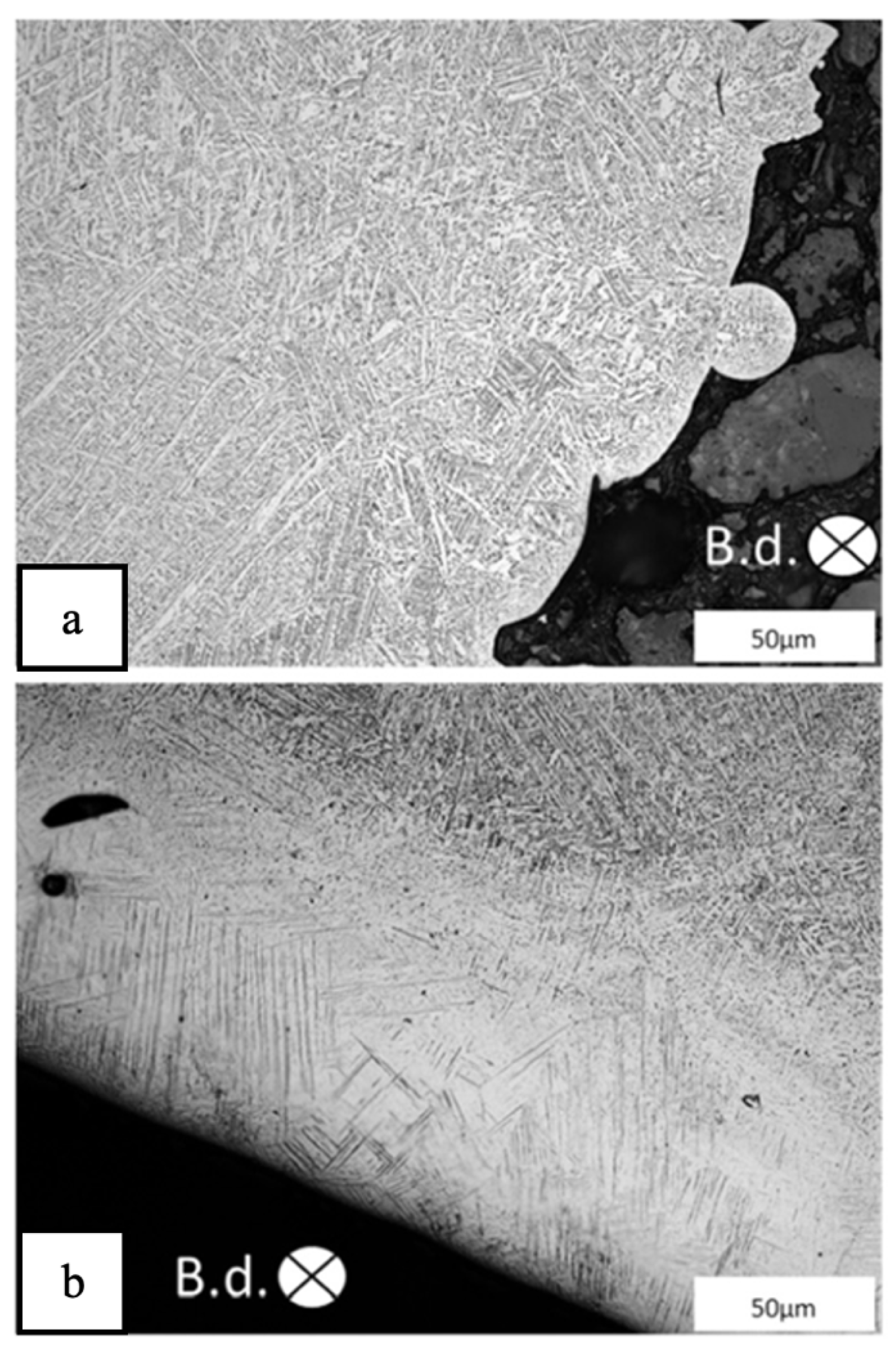
The surface roughness of the Ti6Al4V part produced by LPBF was reduced from 80 µm to 60 µm after five laser scans (number of laser re-melting passes) using LP methods [40]. The as-built microstructure contains a mixture of α + β, as shown in Figure 3a. However, the microstructure changed to a fine α′-structure (martensite) to the depths of 110–160 µm, as shown in Figure 3b. Using load control with a stress ratio of R = 0.10 and a frequency of 20 Hertz, constant amplitude fatigue testing was conducted. The fatigue strength was 50% lower (−130 Mpa) than the as-built strength. In conclusion, reducing surface roughness alone will not increase fatigue life unless other material characterizations below the smooth surfaces are considered, such as residual surface stress, microstructure, and crack initiation [40].
In general, smoothing the surface roughness can help to avoid stress points and the early stages of crack initiation and growth. In SSM, micro-holes and cracks are sealed because it melts the remaining powder on the surface. On the other hand, SOM negatively affects fatigue behavior because it initiates more porosity and cracking, which causes fatigue fracture to occur rapidly [21,22].
Fabricating Ti6Al4V using electron beam melting (EBM) will cause changes in both the orientation of the melted surface and the direction of beam scanning. As a result, significant residual tensile stresses can form near the surface. The grain structure and texture can differ at 200 μm depth due to the remolten surface layer, and the grains regrow vertically to the molten surface [41]. During LP, HAZ was found to be ultimately ß annealed, and it may become martensitic upon cooling. At the same time, conventional heat treatment for stress relief can bring the residual stress down to near zero [41,42]. By measuring the surface roughness at the micro-scale using a nano focus µScan laser profilometer and a white light interferometer with different resolutions before and after LP, significant results have been found in reducing the surface roughness from Ra = 21.46 µm for the as-built surface to Ra = 0.51 µm after LP [41].
Another study [43] investigated the influence of LP without a stress relief process on the strength of fatigue life. Fatigue tests with a fully reversed (R = −1) under strain control were carried out. Compared to as-built samples, the results revealed enhanced high-cycle fatigue strength due to the reduction in the surface roughness and decreased low-cycle fatigue strength due to residual stresses that occurred from LP. However, specific stress reliever mechanisms improved fatigue strength under low- and high-cycle fatigue loads [43].
3.2. Microstructure and Surface Quality of Titanium Alloy
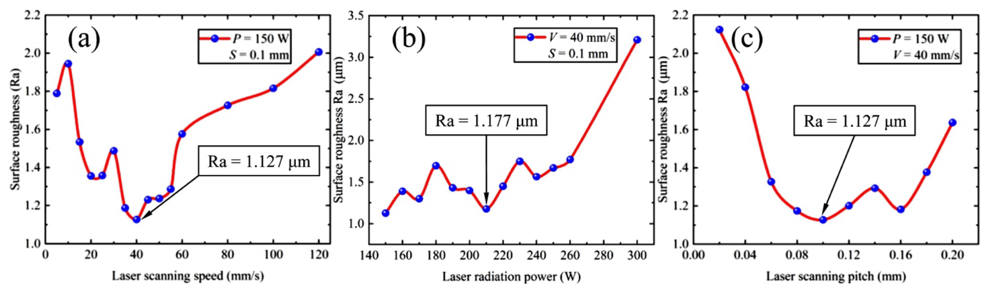
The effect of the LP process parameters on the resultant surface roughness strongly depends on the laser power (P). Increasing the laser power with constant scanning velocity (v) equal to 40 mm/s and scanning pitch (S) of 0.1 mm resulted in an increase in surface roughness of Ti alloy from 1.127 μm at 150 W to 3.25 µm at 300 W, as shown in Figure 4. Due to the SSM process that enables the removal of surface defects and the creation of a smoother surface, SSM may result in better surface quality and reduced surface roughness. However, the technique’s efficacy depends on several variables, and the optimal laser parameters must be chosen depending on the material and the desired surface finish.
As temperatures rise, the surface tension of molten Ti6Al4V decreases because the temperature coefficient of surface tension is negative. When the molten pool begins, the temperature gradient is greatest in the center and diminishes to the lowest at the molten pool’s edge. Furthermore, the surface tension gradient formation spreads gradually from the surface’s center (high temperature) to the molten pool’s edge. As a result of the action of the surface tension gradient and gravity, the molten liquid flows back to the solidification area and the edge of the molten pool. Gravity causes a different distribution of liquid height (ripple) in the molten pool, which increases surface roughness [44,45,46]. The result of numerical modeling showed that the maximum temperature is more sensitive to laser power than laser scan speed [47].
Ti6Al4V alloy powder has more flowability because its particles are rounder than AlSi10Mg, 316L, and IN718 alloy powders [48]. As a result, the layer’s homogeneity and the final components’ surface roughness are influenced to be smooth. After LP, the initial peak–valley value of additively manufactured Ti6Al4V alloy is lowered from 70 μm to around 10 μm [47,48]. In Figure 5 (left), the surface roughness was reduced due to the energy density of the LP as determined by laser power, laser speed, and hatch space. The low energy density cannot penetrate the surface of the part, which results in insufficient energy to melt the surface. As a result of high energy, the solidification rates take long enough to form a molten pool that adequately distributes the wet martial under the effect of gravity and surface tension. The effect of the laser power is significantly more than the laser speed. Sample no. 7 has shown a better reduction in surface roughness by 60%. The reason is that the energy density was high (133.33 J/mm3) among other samples. In Figure 5 (right), number 7 achieved excellent surface roughness with a laser power of 400 W and a laser speed of 0.5 m/s [48].
The effect of rescanning cycles (number of laser re-melting passes) on the characteristics of the Ti6Al4V SLM sample was investigated. The residual stress increased with a single rescanning cycle and decreased with multiple rescanning cycles. The ultimate tensile strength (UTS), yield strength, micro-hardness, and micro-strain of the samples all increase as the laser re-melting cycles increase from 0 to 3 but decrease after the fourth time of rescanning [47]. In another study [49], the authors observed a significant reduction in roughness and porosity after applying the number of laser re-melting passes in each layer.
On the other hand, various laser scanning speed parameters with constant laser power P of 150 W and a constant scanning pitch S of 0.1 mm can significantly affect surface roughness, as shown in Figure 4. The lowest roughness was obtained at Ra 1.127 μm with a laser speed of 40 mm/s. The laser speed between 0 and 35 mm/s was evidence of a high energy density on the surface. Re-melting will be beyond the surface valley because laser power in this situation is considered a high amount. The molten metal flowed back to the solidified metal region. However, the laser speed ranged from 50 to 120 mm/s, indicating a low energy density on the surface. As a result, re-melting will be insufficient because the laser power is considered low in conjunction with scanning speed, and the molten pool was not initiated [26].
Medical implants using Ti-6Al-4V Grade 23 ELI with superior surface qualities via the LPBF method, followed by LP using a CO2 laser source, were investigated. The surface qualities of the products mentioned above are compared to those manufactured by AM techniques. LPBF paired with LP yields a surface roughness reduction of almost 80% and a peak-to-valley reduction of 90%. In addition, a significantly reduced processing time is reported, and the procedure is more cost-effective than other methods. The uses of a CO2 laser to decrease surface roughness and enhance surface physical properties were examined, and cylindrical and flat samples were manufactured. The result was around an 80% decrease in average surface roughness and a 90% reduction in peak-to-valley distance. The surface roughness and (Sa) values are more likely to improve when there is a large percentage of overlap in the scanning track [50].
In another study [51], the effect of femtosecond LP and overlapping rate on the surface roughness of Ti-6Al-4V was investigated. It was observed that different overlapping rates produced nanoparticles that were caused by femtosecond laser. No evidence of microcracks was observed, and the surface had optimal roughness due to low thermal stress and residual stress. Low laser overlapping rates result in small nanoparticles produced by laser ablation and femtosecond laser fragmentation. High laser overlapping rates result in large nanoparticles produced from small nanoparticles via laser melting. The heat was affected as the laser overlapping rates increased, and the surface roughness was reduced by 1.381 μm [51].
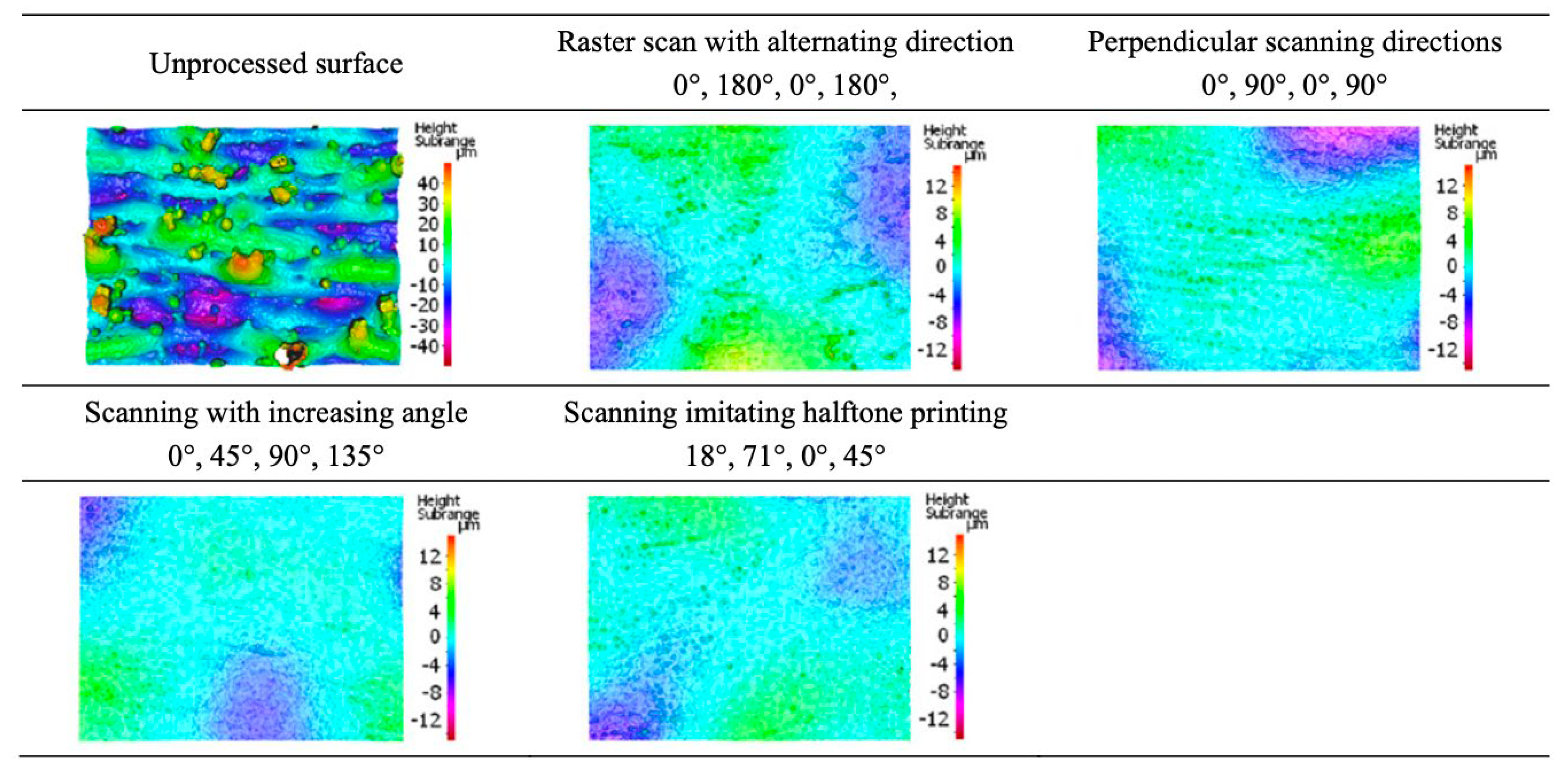
The effects of various scanning strategies, laser parameters, and the initial surface were examined [1]. Four different scanning strategies with varying angles were used. The best scanning pattern on better initial surface quality obtained an 85% reduction in surface roughness after 12 scans with angles (18°, 71°, 0°, and 45°) of halftone. The effect of three different scanning strategies on the relative density of a Ti6Al4V AM part was investigated. The fiber laser beam quality and the process environment are crucial for attaining greater relative densities. Owing to the 90° rotation of the scan lines in each layer, the alternating bi-directional strategy resulted in the maximum relative density due to fewer existing unmolten zones between scan tracks and a 59% reduction in thermal stress [52,53].
Different laser input and scanning strategies were concentrated on reducing the surface roughness of Ti-6Al-4V alloy using the predetermined area subjected to selective site melting by laser processing in this technique. The surface roughness of the processed alloy has decreased from Ra = 44.14 µm to Ra = 3.69 µm. Indeed, this method successfully reduces 90% of the surface roughness. However, this technique might result in surface defects, and care is needed to minimize surface defects [54]. Process parameters for titanium are summarized in Table 4.
4. Laser Polishing of Inconel Alloys
Nickel-based superalloys are distinguished by their exceptional combination of high-temperature strength, hardness, and corrosion or oxidation resistance. These alloys are widely used in power generation and aviation turbines, rocket engines, and other challenging environments, such as nuclear power plants and chemical processing facilities [8,55,56,57].
4.1. Microstructure and Surface Quality of Inconel Alloys
IN718, manufactured via laser metal deposition (LMD), was investigated to determine the relationship between laser power, scanning speed, and laser diameter. The melting of the outer layers has been assisted by raising the laser power to some level. After that, the increased laser energy will not be able to polish the surface layer any longer effectively, and it may have a negative effect. This is because high laser energy may damage the surface and extend beyond the surface valley that marks the transition between the SSM and SOM regimes. LP should not increase the peak–valley distance [7]. Another study performed in situ laser polishing simulations at 50 W, 90 W, 130 W, and 170 W and studied all specimens’ surface morphological features and underlying mechanisms; 50 W and 90 W surface morphology were unaltered compared to the as-built ones. The molten pool’s lifespan was extended when the laser power reached 130 W. The LP reduced the surface roughness of the SLM specimens from 20.0 ± 1.25 µm to 13.3 ± 0.35 μm [58,59,60].
The melt pool geometry (single track) of SLM IN625 was investigated. Laser power significantly impacts the melt pool more than scanning speed. It was observed that increasing laser power and decreasing scan speed significantly increase track width and melt depth. Furthermore, increasing laser power reduced the contact angle of the melt pool; however, the scan speed had less of an effect on the height and surface roughness of the melt pool [61].
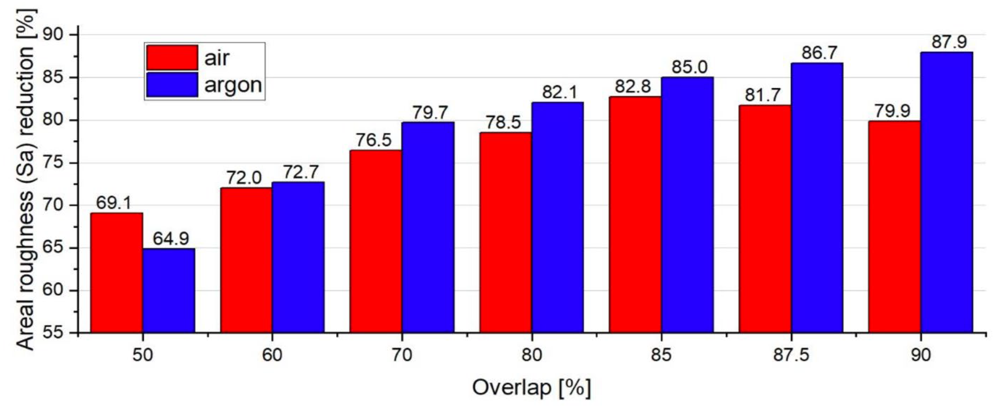
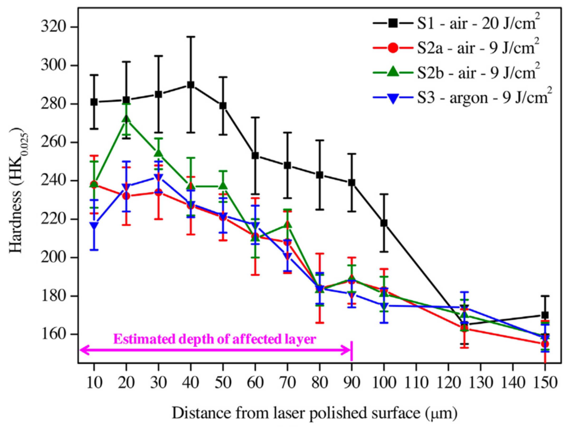
The effect of overlap in LP in air and argon environments was investigated. Under air conditions, all laser-polished samples showed the formation of an oxide layer, a dark surface color, and microcracks. The surface is more stable in an argon environment, and there are no signs of microcracks because of less oxidation during the process. As shown in Figure 6, increasing the overlap significantly reduces surface roughness (Ra). However, increasing the overlap after 85 percent increases the surface roughness in the air case due to melt-pool instability and surface overheating. Process parameters for Inconel are summarized in Table 5.
4.2. Mechanical Properties
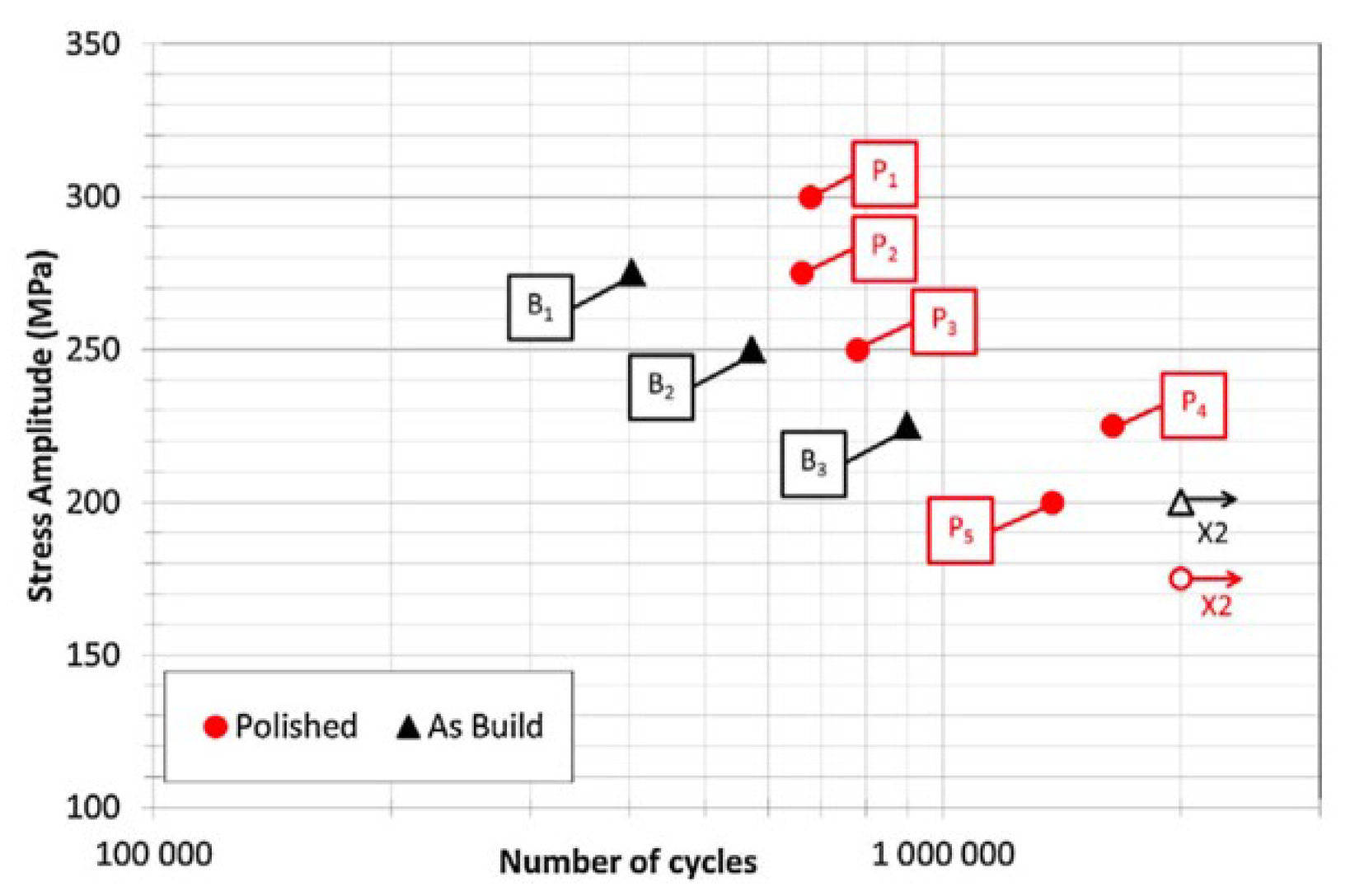
The effect of hatching and contour on the initiation of fatigue crack in the IN625 SLM part was investigated. Seven as-built and laser-polished samples were subjected to a fatigue test at a 20 Hz frequency, using a load R-ratio of −1 and increasing the stress by 25 MPa increments to determine the number of cycles to failure. It was found that the optimum parameters resulted in excellent surface roughness and porosity reduction. Fatigue testing on as-built and polished samples revealed three mechanisms that cause fatigue damage, which are unmolten particles during the SLM process, porosity that occurs during SLM, and local plasticity that appears in the microstructure of the material. The fatigue strength of the polished and built samples is shown in Figure 7. With 200 MPa, the polished sample with fewer porosities can withstand more than 2 × 10⁶ cycles. The difference in fatigue strength between polished and as-built samples is approximately 10%, even though the surface roughness of as-built samples is high [63].
The LP influence on the mechanical properties of the IN718 part was investigated. After LP, the researchers observed that the grain in the polished layer was refined, and the precipitation strengthening phase (γ″ phase) increased. The micro-hardness improved to 440 HV compared to the as-built 345 HV. Due to an increase in hardness, the wear rate increased by 90% [16].
5. Cobalt Chromium—CoCr
CoCr-based alloys are frequently used in dental treatment and joint implantation because of their low cost and exceptional resistance to corrosion and mechanical characteristics, such as high stiffness, high strength, heat resistance, and non-magnetic property [64].
5.1. Microstructure and Surface Quality of Cobalt Chromium
The effect of LP on the surface microstructure and corrosion resistance of AM CoCr was studied. Table 6 exhibits the LP parameters used in this study [65]. It was found that laser-polished specimens have a higher corrosion resistance of about 30% compared to other polishing methods, such as thermos mechanical treatment. The important parameters to obtain optimized results are the laser power and the distance of the object [65]. This result matches Yung et al.’s [15] study; it was found that argon gas significantly smooths the surface roughness. The optimal parameter for laser polishing the AM CoCr part. The flow concentrations of air, nitrogen, and argon were 2.0 L/min, 6.0 L/min, and 10.0 L/min. They mentioned that the CoCr sample performed best with argon gas at a flow rate of 6.0 L/min [66]. In another study, a 93% reduction in surface roughness of a complex surface geometry was achieved by adjusting the distance of the laser along with the surface shape [15].
The effect of CW on 3D fabricated samples was studied. The main parameter that was concentrated was scanning at different angles. The halftone strategy in Figure 8 was the most effective among the three methods studied. Angles of halftones were (18°, 71°, 0°, and 45°). The halftone strategy enhanced the surface by up to 96% on the macro-scale for cobalt chrome. The spatial frequency technique has been used in the research for constant LP of individual lines. It eliminates the heat build-up effect and enables the prediction of the time frame of molten metal [1]. The capillary smoothing surface prediction model of CW LP was examined to measure the melt pool and temperature. The model captured the general smooth behavior during LP [67].
5.2. Mechanical Properties
A slight enhancement in hardness (about 8%) of a complex surface geometry was achieved by adjusting the distance of the laser along with the surface shape compared to the as-built surface. A hardness test was conducted each 100 µm from the surface to the in-depth. The average hardness values are shown in Figure 9. There was a reduction in hardness from the surface to the depth of the material. The highest value on the surface is 413 HV and remained at 150 μm of the depth due to the heat-affected zone. At the final depth, 350 μm, the hardness value was changed to 384 HV. This demonstrated that the LP could slightly improve the surface compared to the as-received hardness [15].
6. Laser Polishing of Steel
Steel components manufactured by AM face numerous challenges. These materials have a high surface roughness, making them unsuitable for various applications, including aerospace, medical components, automotive, and many others [68,69,70,71,72,73,74].
6.1. Microstructure and Surface Quality of Steel
The PW and CW laser irradiation outcomes were examined and compared in many different studies [75,76,77,78,79,80,81]. The material they investigated was 18Ni Maraging steel. Laser irradiation was applied to the top and the side of the sample. One of the process parameters that was introduced is a pitch distance of 25–50 μm. It was found that laser power significantly impacts the surface roughness of the part, whereas the combination of low power with high speed or low speed was not significant. However, combining high power with either low speed or high speed resulted in melt pool disruptions. Other studies indicated that the diameter of the spot is perhaps the most difficult to monitor. The beam spot diameter of a focused laser beam on a working surface is identified, and the beam type and optics determine it [82]. In another study [83], the effect of two different inert gases (argon and nitrogen) on the surface roughness after laser micro-polishing was investigated. It was shown that nitrogen gas is more suitable for the laser micro-polishing process. In addition, after laser micro-polishing, there is no sign of defect or hot cracks, and the surface roughness was significantly reduced. The porosity of the AM part with the untreated surface is approximately 0.77%, and this percentage decreases after LP to approximately 0.036% [14,84].
Furthermore, corrosion-resistant austenitic X2CrNiMo17-12-2 steel was investigated [85]. For PW, the optimized result was achieved when the laser diameter was measured at 12 mm and intensity at 1.74 kW/mm2. Any change in the spot diameter increasing or decreasing resulted in higher surface roughness as in EV. While any decrease in intensity caused a low melting bath, any increase caused a high melting bath. When the power is at the minimum, there is no effect on the surface of CW. Increasing laser power at 1400 W with a feed rate ranging from 200 to 350 mm/min decreased the surface roughness to less than 0.25 μm. In a similar study, the surface roughness was reduced by 91%. It was observed that high power promotes oxidation, whereas low power does not. The higher the power, the fewer the cracks, but there was a greater number of cavities [17]. Another study [86] showed that the number of scanning passes had a more significant impact than scanning speed. The optimized process parameters for LP 316L were a laser scanning velocity of 100 mm/s with three scanning passes [86]. Moreover, an investigation of the influence of laser and overlap parameters on stainless steel 316L found that the maximum reduction in the surface roughness was achieved at 0.2 μm (95%) with optimized parameters set (overlap 95% and energy density 9 J/cm2) [87].
The influence of compression of powder distribution on the building plate and the laser re-melting of 316 L on the density, microstructure, and surface roughness was investigated. It was found that the density improved up to 3% after raising the powder compression ratio three times depending on the selected energy density between 26.7 and 68 J/mm3 and re-melting the layers with a double pass. This decreased the elastic modulus by 17% [6,88].
The effect of powder compression and laser re-melting (number of laser re-melting passes) on the microstructure and mechanical properties of 316 AM LPBF parts was studied [88]. A 3% increment in density and a 50% reduction in the surface roughness after double laser passes at each layer were observed. Another study reported a significant decrease in pores and an increase in surface smoothness after re-melting results [89]. In addition, it was found that the optimized parameters for fabrication should not be the optimized parameters for the re-melting process [90]. The re-melting scanning speed played an essential role in controlling the elimination effect on pores. A higher re-melting scanning speed does not eliminate most of the pores because of the limited energy input. In contrast, a lower re-melting scanning speed introduces new types of pores caused by the unstable molten pool [91]. High thermal gradients cause delamination within layers during building, such as residual stress and external and internal cracking [92].
6.2. Mechanical Properties
The hardness improved slightly by 14% after applying high-power CW LP compared to the hardness of the steel of the AM tool received; on the other hand, it increased by 9% after applying low-power PW [17]. Two different scanning strategies were used to study their influence on microhardness. Variation of flow strategies was found to cause microhardness variations in AM parts. Both scanning methods are described in detail in Table 7. Shallow dimples are noticed during XY scanning because of higher interlayer bonding. Furthermore, voids of 35–45 μm are reported for the X scanning, resulting in early crack development and reduced strength of final AM parts. The porous structure forms in the components of AM primarily due to the inadequate density of the laser to liquefy the powder [93]. In another study [94], tensile strength on as-built samples from two various machines was shown to have yield strengths of LPBF 316L SS three times higher than those as-cast.
The influence of multi-step LP on the H1 tool steel surface was studied. It was found that an increase in hardness and grain refinement was due to multistep LP [95,96]. After LP of stainless steel, the micro-hardness was affected in a range of depth up to 90–100 μm, as shown in Figure 10 [88]. The micro-hardness of a steel surface was measured after LP. A Rockwell hardness (HRC) test was performed on the surface, which yielded an initial hardness of 62 HRC (untreated) [18]. Furthermore, the thickness of the melted sheet, Zone A, was 200 μm, with a hardness of 43 HRC, as shown in Figure 11. The hardness in Zone B is moderate. The hardness reached 62 HRC with a thickness of 350 μm. The hardness was reduced to 54 HRC in Zone C with a thickness of 100 µm. The final zone, which is the core material of the part, has an initial value of 62 HRC. According to these findings, a decrease in hardness is due to the increase in energy density. As a result, energy density must be limited to avoid the risk of lowering hardness. Another study indicated that the average microhardness of the as-built sample is about 208 HV, and it remains roughly steady with depth. The maximum hardness (~10 μm from the upper surface) of Sample 1, Sample 2, Sample 3, and Sample 4 following the laser finishing is 241 HV, 228 HV, 262 HV, and 256 HV, respectively. The hardness of the samples increased after the LP process [97]. Process parameters for steel are summarized in Table 8.
Avilés et al. tested AISI 1045 steel during the LP process under N2 gas and a regular atmosphere to improve fatigue life. Under load control, with a 20 Hz frequency and a stress fatigue ratio of R = 0.1, 25 mirror-finish fatigue samples were tested across five stress levels: 545, 515, 500, 485, and 470 MPa. The specimens treated under inert gas conditions had a 7.5% longer fatigue life than those treated in oxygen. Furthermore, a very thin layer of Fe oxides was formed on the specimen processed in an oxygen atmosphere [98,99].
7. Machine Learning in Laser Polishing
Laser polishing and machine learning have shown an improvement in surface quality and surface microstructure for LPBF Ti-6Al-4 V alloy. An artificial neural network (ANN) algorithm was used in this study [99] and included three input nodes as three process parameters (laser power, scanning velocity, and track offset) with different levels of each parameter. The output was the surface roughness of the laser-polished area. A total of 512 groups represented the process parameters and their levels. Kolmogorov’s theorem was used to obtain the number of hidden nodes. Figure 12a shows the topological network structure. The mean absolute error (MAE), root means square error (RMSE), and coefficient of determination (R2) were presented in this model as predictive performances. The process optimization of the algorithms is in Figure 12b. The findings of this model were that the thermal effect and high cooling rates play essential roles in the microstructure formation process [100,101,102,103].
Another study used machine-learning-based image processing for LP on AM PH-steel parts using convolutional neural networks (CNN) to identify optimal laser-polished surface quality and integrity. CNN is a machine-learning method that can classify images and consists of a series of hierarchically arranged convolutional layers that gradually assemble low-level elements into high-level elements to improve and characterize the input image. CNN was trained with 432 images as a data set that was taken from pre-processed images with segments into the size of 333 px × 150 px. A total of 80% (344) of the images were used for CNN training, and 20% (88) were used for CNN validation. The CNN identified LP process conditions based on hatch spacing and an overlapping ratio with an accuracy of up to 97% [104,105].
In addition, high-speed thermographic imaging was employed for visualization, evaluation, and machine-learning-based Bayesian classification of LP methods. Three steps were set to evaluate the thermographic images, the temperature contour of each image, as shown in Figure 13, and the MATLAB code to obtain all information that is collected from the images. As a result, machine learning was capable of obtaining the optimized LP process [102].
8. Future Work
As AM enables the production of complex geometries that are challenging to produce with conventional manufacturing techniques, often, these components have a surface roughness that requires smoothing or polishing. For instance, the research can concentrate on developing methods or strategies for using LP to smooth the intricate geometrical features of AM parts without impacting their structural integrity. Since AM can manufacture multiple materials in a single fabrication project, LP can be optimized for processing materials with different physical properties. Therefore, future research can investigate establishing LP parameters and processes for multi-material AM components.
9. Conclusions
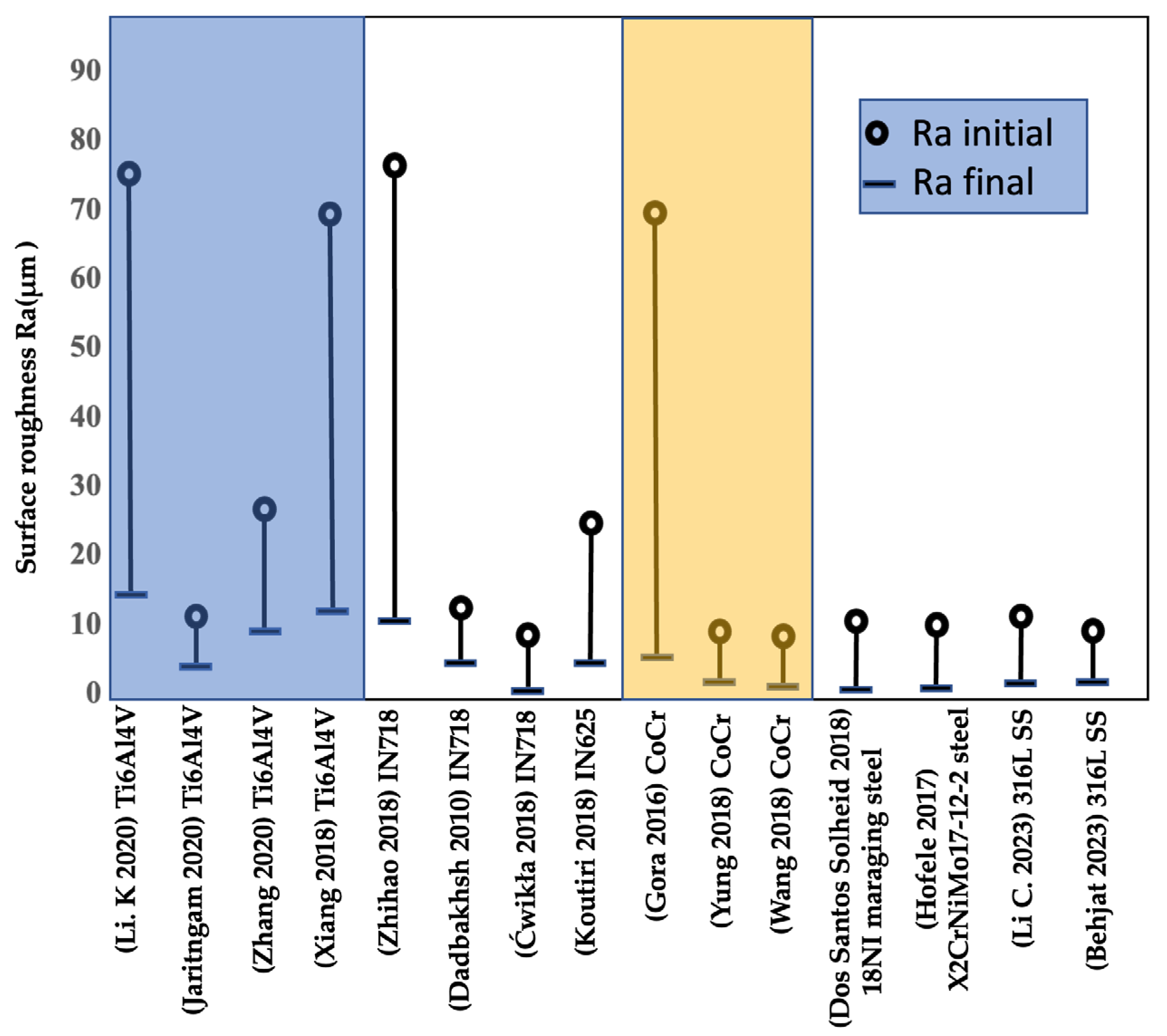
This review article aims to assemble current knowledge to propose the optimum process parameters to improve the surface quality mechanical properties of titanium alloys, stainless steel, cobalt–chromium (CoCr) alloys, and Inconel alloys, as shown in Figure 14. Numerous investigations have been carried out to determine the influence of LP on AM components. The findings indicated a considerable improvement in the overall performance of the sample in terms of surface roughness and mechanical properties. Controlling the process parameters results in a high-quality surface finish. The Gaussian laser beam profile significantly demonstrated a smooth melt width in multiple experiments because of the laser beam’s small diameter, which delivers greater energy density. Multiple scanning after each layer during the fabrication of an AM part improves the density and mechanical properties while increasing production time.
In conclusion, the following points are summarized: macro and micro are the two types of LP. Macro-polishing is mainly accomplished via a continuous wave laser beam. With continuous re-melting of the specimen’s upper outer surface, polishing a 10–80 μm range is possible [21]. Micro-polishing irradiates the surface using laser pulses performed in pulse mode, with pulse length tP and repetition frequency fP influencing surface treatment [23,106]. In LP, SOM is unfavorable, causing the surface to become rougher and creating undesirable pores. In the SSM process, a thin layer of powder is melted, smoothing out the material’s valleys and generating a smoother surface. Finally, the LP process could enhance the mechanical properties of AM metals. Several studies indicated the effectiveness of LP in improving AM metal mechanical properties.
Author Contributions
Conceptualization, M.A. and A.A. (Abdalmageed Almotari); methodology, M.A. and A.A. (Abdalmageed Almotari); software, M.A. and A.A. (Abdalmageed Almotari); validation, M.A., A.A. (Abdalmageed Almotari) and A.Q.; formal analysis, A.A. (Anwar Algamal); investigation, A.Q.; resources, A.Q.; data creation, M.A.; writing—original draft preparation, A.A. (Abdalmageed Almotari); writing—review and editing, M.A. and A.A. (Anwar Algamal); visualization, A.Q.; supervision, A.Q. All authors have read and agreed to the published version of the manuscript.
Funding
This research received no external funding.
Data Availability Statement
No new data were created or analyzed in this study. Data sharing does not apply to this article.
Conflicts of Interest
The authors declare no conflict of interest.
Nomenclature
| AM | Additive manufacturing |
| ANN | Artificial neural network |
| CNN | Convolutional neural networks |
| EBM | Electron beam melted |
| HAZ | Heat-affected zone |
| HIP | Hot isotactic pressing |
| LAM | Laser additive manufacturing |
| LMD | Laser metal deposition |
| LENS | Laser engineered net shaping |
| LBPB | Laser beam powder bed |
| LPBF | Laser powder bed fusion |
| LP | Laser polishing |
| Ra | The arithmetical mean height of a line |
| Sa | The arithmetical mean height of the scale limited surface |
| SR | Stress relieved |
| SLM | Selective laser melting |
| SLS | Selective laser sintering |
| SSM | Surface shallow melting |
| SOM | Surface over melting |
| 3D | Three-dimensional |
| 3DP | Inkjet 3D printer |
References
- Gora, W.S.; Tian, Y.; Cabo, A.P.; Ardron, M.; Maier, R.R.J.; Prangnell, P.; Weston, N.J.; Hand, D.P. Enhancing surface finish of additively manufactured titanium and cobalt chrome elements using laser based finishing. Phys. Procedia 2016, 83, 258–263. [Google Scholar] [CrossRef]
- Yang, T.; Liu, C.; Chen, T.; Shao, M.; Jiang, C.; Lu, C.; Song, S. Parameter Optimization of RB-SiC Polishing by Femtosecond Laser. Materials 2023, 16, 1582. [Google Scholar] [CrossRef] [PubMed]
- Turk, T.; Leu, M.C. Experimental study for improving the productivity of laser foil printing. Int. J. Adv. Manuf. Technol. 2023, 125, 5149–5162. [Google Scholar] [CrossRef]
- Lohser, J. Evaluation of Electrochemical and Laser Polishing of Selectively Laser Melted 316l Stainless Steel; California Polytechnic State University: San Luis Obispo, CA, USA, 2018. [Google Scholar]
- Yang, G.; Wang, B.; Tawfiq, K.; Wei, H.; Zhou, S.; Chen, G. Electropolishing of surfaces: Theory and applications. Surf. Eng. 2017, 33, 149–166. [Google Scholar] [CrossRef]
- Ali, M.; Almotari, A.; Algamal, A.; Alafaghani, A.; Abedi, H.; Qattawi, A. Effect of in-situ laser polishing on microstructure, surface characteristics, and phase transformation of lpbf martensitic stainless steel. In Proceedings of the ASME 2023 18th International Manufacturing Science and Engineering Conference, New Brunswick, NJ, USA, 12–16 June 2023; pp. 1–10. [Google Scholar]
- Dadbakhsh, S.; Hao, L.; Kong, C.Y. Surface finish improvement of LMD samples using laser polishing. Virtual Phys. Prototype 2010, 5, 215–221. [Google Scholar] [CrossRef]
- Basha, S.M.; Bhuyan, M.; Basha, M.M.; Venkaiah, N.; Sankar, M.R. Laser polishing of 3D printed metallic components: A review on surface integrity. Mater. Today Proc. 2019, 26, 2047–2054. [Google Scholar] [CrossRef]
- Ma, C.P.; Guan, Y.C.; Zhou, W. Laser polishing of additive manufactured Ti alloys. Opt. Lasers Eng. 2017, 93, 171–177. [Google Scholar] [CrossRef]
- Zhang, J.; Lee, Y.J.; Wang, H. A Brief Review on the Enhancement of Surface Finish for Metal Additive Manufacturing. J. Miner. Met. Mater. Eng. 2021, 7, 1–14. [Google Scholar]
- Algamal, A.; Albat, M.A.; Ramineni, L.; Ali, M.; Almotari, A.; Alafaghani, A.; Sun, J.-Q.; Qattawi, A. Cradle-to-gate life cycle analysis of origami-based sheet metal for automobile parts. In Proceedings of the ASME 2022 International Mechanical Engineering Congress and Exposition, Columbus, OH, USA, 30 October–3 November 2022; pp. 1–10. [Google Scholar]
- Pong-Ryol, J.; Tae-Sok, J.; Nam-Chol, K.; Xing, F.; Kum-Hyok, J. Laser micro-polishing for metallic surface using UV nano-second pulse laser and CW laser. Int. J. Adv. Manuf. Technol. 2016, 85, 2367–2375. [Google Scholar] [CrossRef]
- Fraunhofer Institute for Laser Technology (ILT). Laser Micro Polishing of Aluminum Materials. 2011. Available online: https://www.ilt.fraunhofer.de/content/dam/ilt/en/documents/annual_reports/ar11/JB11_P96.pdf69572 (accessed on 3 April 2023).
- Yasa, E.; Kruth, J.P. Microstructural investigation of selective laser melting 316L stainless steel parts exposed to laser re-melting. Procedia Eng. 2011, 19, 389–395. [Google Scholar] [CrossRef]
- Yung, K.C.; Xiao, T.Y.; Choy, H.S.; Wang, W.J.; Cai, Z.X. Laser polishing of additive manufactured CoCr alloy components with complex surface geometry. J. Mater. Process. Technol. 2018, 262, 53–64. [Google Scholar] [CrossRef]
- Zhihao, F.; Libin, L.; Longfei, C.; Yingchun, G. Laser Polishing of Additive Manufactured Superalloy. Procedia CIRP 2018, 71, 150–154. [Google Scholar] [CrossRef]
- Yung, K.C.; Zhang, S.S.; Duan, L.; Choy, H.S.; Cai, Z.X. Laser polishing of additive manufactured tool steel components using pulsed or continuous-wave lasers. Int. J. Adv. Manuf. Technol. 2019, 105, 425–440. [Google Scholar] [CrossRef]
- Ukar, E.; Lamikiz, A.; López de Lacalle, L.N.; del Pozo, D.; Arana, J.L. Laser polishing of tool steel with CO2 laser and high-power diode laser. Int. J. Mach. Tools Manuf. 2010, 50, 115–125. [Google Scholar] [CrossRef]
- Ramos-Grez, J.A.; Bourell, D.L. Reducing surface roughness of metallic freeform-fabricated parts using non-tactile finishing methods. Virtual Model. Rapid Manuf. Adv. Res. Virtual Rapid Prototyp. 2003, 21, 297–316. [Google Scholar] [CrossRef]
- Morgan, R.H.; Papworth, A.J.; Sutcliffe, C.; Fox, P.; O’Neill, W. High density net shape components by direct laser re-melting of single-phase powders. J. Mater. Sci. 2002, 37, 3093–3100. [Google Scholar] [CrossRef]
- Krishnan, A.; Fang, F. Review on mechanism and process of surface polishing using lasers. Front. Mech. Eng. 2019, 14, 299–319. [Google Scholar] [CrossRef] [Green Version]
- Li, J.; Zuo, D. Laser polishing of additive manufactured Ti6Al4V alloy: A review. Opt. Eng. 2021, 60, 020901. [Google Scholar] [CrossRef]
- Temmler, A.; Willenborg, E.; Wissenbach, K. Laser Polishing. Laser Appl. Microelectron. Optoelectron. Manuf. XVII 2012, 8243, 82430W. [Google Scholar] [CrossRef]
- Ermergen, T.; Taylan, F. Review on Surface Quality Improvement of Additively Manufactured Metals by Laser Polishing. Arab. J. Sci. Eng. 2021, 46, 7125–7141. [Google Scholar] [CrossRef]
- Bordatchev, E.V.; Hafiz, A.M.K.; Tutunea-Fatan, O.R. Performance of laser polishing in finishing of metallic surfaces. Int. J. Adv. Manuf. Technol. 2014, 73, 35–52. [Google Scholar] [CrossRef] [Green Version]
- Li, K.; Zhao, Z.; Zhou, H.; Zhou, H.; Jin, J. Numerical analyses of molten pool evolution in laser polishing Ti6Al4V. J. Manuf. Process. 2020, 58, 574–584. [Google Scholar] [CrossRef]
- Zhao, S.; Wang, D.; Liu, J.; Yu, M.; Yan, R.; Cui, E.; Liu, S.; Lei, C. Analysis of molten pool dynamics and surface smoothing time scale in laser polishing alloy materials. Opt. Laser Technol. 2023, 161, 109183. [Google Scholar] [CrossRef]
- Li, J.; Jin, Y.; Chang, Y.; Zuo, D. Finite element simulation and experimental study of single-laser track in laser polishing of Ti6Al4V. Int. J. Adv. Manuf. Technol. 2022, 121, 4571–4581. [Google Scholar] [CrossRef]
- Marimuthu, S.; Triantaphyllou, A.; Antar, M.; Wimpenny, D.; Morton, H.; Beard, M. Laser polishing of selective laser melted components. Int. J. Mach. Tools Manuf. 2015, 95, 97–104. [Google Scholar] [CrossRef] [Green Version]
- Qin, J.; Chen, Q.; Yang, C.; Huang, Y. Research process on property and application of metal porous materials. J. Alloys Compd. 2016, 654, 39–44. [Google Scholar] [CrossRef]
- Dutta, B.; Froes, F.H.S. The additive manufacturing (AM) of titanium alloys. Met. Powder Rep. 2017, 72, 96–106. [Google Scholar] [CrossRef]
- Ventola, C.L. Medical Applications for 3D Printing: Current and Projected Uses. Pharm. Ther. 2014, 39, 704–711. [Google Scholar]
- Ngo, T.D.; Kashani, A.; Imbalzano, G.; Nguyen, K.T.Q.; Hui, D. Additive manufacturing (3D printing): A review of materials, methods, applications and challenges. Compos. Part B Eng. 2018, 143, 172–196. [Google Scholar] [CrossRef]
- Narasimharaju, S.R.; Zeng, W.; See, T.L.; Zhu, Z.; Scott, P.; Jiang, X.; Lou, S. A comprehensive review on laser powder bed fusion of steels: Processing, microstructure, defects and control methods, mechanical properties, current challenges and future trends. J. Manuf. Process. 2022, 75, 375–414. [Google Scholar] [CrossRef]
- Kim, J.H.; Kim, M.Y.; Knowles, J.C.; Choi, S.; Kang, H.; Park, S.; Park, S.M.; Kim, H.W.; Park, J.T.; Lee, J.H.; et al. Mechanophysical and biological properties of a 3D-printed titanium alloy for dental applications. Dent. Mater. 2020, 36, 945–958. [Google Scholar] [CrossRef] [PubMed]
- Li, Y.H.; Wang, B.; Ma, C.P.; Fang, Z.H.; Chen, L.F.; Guan, Y.C.; Yang, S.F. Material characterization, thermal analysis, and mechanical performance of a laser-polished Ti Alloy prepared by selective laser melting. Metals 2019, 9, 112. [Google Scholar] [CrossRef] [Green Version]
- Zhou, J.; Liao, C.; Shen, H.; Ding, X. Surface and property characterization of laser polished Ti6Al4V. Surf. Coatings Technol. 2019, 380, 125016. [Google Scholar] [CrossRef]
- Shen, B.; Li, H.; Liu, S.; Zou, J.; Shen, S.; Wang, Y.; Zhang, T.; Zhang, D.; Chen, Y.; Qi, H. Influence of laser post-processing on pore evolution of Ti–6Al–4V alloy by laser powder bed fusion. J. Alloys Compd. 2020, 818, 152845. [Google Scholar] [CrossRef]
- Liang, C.; Hu, Y.; Liu, N.; Zou, X.; Wang, H.; Zhang, X.; Fu, Y.; Hu, J. Laser polishing of Ti6Al4V fabricated by selective laser melting. Metals 2020, 10, 191. [Google Scholar] [CrossRef] [Green Version]
- Kahlin, M.; Ansell, H.; Basu, D.; Kerwin, A.; Newton, L.; Smith, B.; Moverare, J.J. Improved fatigue strength of additively manufactured Ti6Al4V by surface post processing. Int. J. Fatigue 2020, 134, 105497. [Google Scholar] [CrossRef]
- Tian, Y.; Gora, W.S.; Cabo, A.P.; Parimi, L.L.; Hand, D.P.; Tammas-Williams, S.; Prangnell, P.B. Material interactions in laser polishing powder bed additive manufactured Ti6Al4V components. Addit. Manuf. 2018, 20, 11–22. [Google Scholar] [CrossRef] [Green Version]
- Alafaghani, A.; Qattawi, A.; Castañón, M.A.G. Effect of manufacturing parameters on the microstructure and mechanical properties of metal laser sintering parts of precipitate hardenable metals. Int. J. Adv. Manuf. Technol. 2018, 99, 2491–2507. [Google Scholar] [CrossRef]
- Lee, S.; Ahmadi, Z.; Pegues, J.W.; Mahjouri-Samani, M.; Shamsaei, N. Laser polishing for improving fatigue performance of additive manufactured Ti-6Al-4V parts. Opt. Laser Technol. 2021, 134, 106639. [Google Scholar] [CrossRef]
- Pfefferkorn, F.E.; Duffie, N.A.; Li, X.; Vadali, M.; Ma, C. Improving surface finish in pulsed laser micro polishing using thermocapillary flow. CIRP Ann. Manuf. Technol. 2013, 62, 203–206. [Google Scholar] [CrossRef]
- Olakanmi, E.O.; Cochrane, R.F.; Dalgarno, K.W. A review on selective laser sintering/melting (SLS/SLM) of aluminum alloy powders: Processing, microstructure, and properties. Prog. Mater. Sci. 2015, 74, 401–477. [Google Scholar] [CrossRef]
- Jaritngam, P.; Tangwarodomnukun, V.; Qi, H.; Dumkum, C. Surface and subsurface characteristics of laser polished Ti6Al4V titanium alloy. Opt. Laser Technol. 2020, 126, 106102. [Google Scholar] [CrossRef]
- Xiang, Z.; Yin, M.; Dong, G.; Mei, X.; Yin, G. Modeling of the thermal physical process and study on the reliability of linear energy density for selective laser melting. Results Phys. 2018, 9, 939–946. [Google Scholar] [CrossRef]
- Zhang, D.; Yu, J.; Li, H.; Zhou, X.; Song, C.; Zhang, C.; Shen, S.; Liu, L.; Dai, C. Investigation of laser polishing of four selective laser melting alloy samples. Appl. Sci. 2020, 10, 760. [Google Scholar] [CrossRef] [Green Version]
- Yu, W.; Sing, S.L.; Chua, C.K.; Tian, X. Influence of re-melting on surface roughness and porosity of AlSi10Mg parts fabricated by selective laser melting. J. Alloys Compd. 2019, 792, 574–581. [Google Scholar] [CrossRef]
- Obeidi, M.A.; Mussatto, A.; Dogu, M.N.; Sreenilayam, S.P.; McCarthy, E.; Ahad, I.U.; Keaveney, S.; Brabazon, D. Laser surface polishing of Ti-6Al-4V parts manufactured by laser powder bed fusion. Surf. Coatings Technol. 2022, 434, 128179. [Google Scholar] [CrossRef]
- Fan, W.; Yang, Y.; Lou, R.; Chen, X.; Bai, J.; Cao, W.; Cheng, G.; Si, J. Influence of energy fluence and overlapping rate of femtosecond laser on surface roughness of Ti-6Al-4V. Opt. Eng. 2019, 58, 1. [Google Scholar] [CrossRef]
- Kruth, J.P.; Badrossamay, M.; Yasa, E.; Deckers, J.; Thijs, L.; Van Humbeeck, J. Part and material properties in selective laser melting of metals. In Proceedings of the 16th International Symposium on Electromachining, ISEM 2010, Shanghai, China, 19–23 April 2010; pp. 3–14. [Google Scholar]
- Kruth, J.P.; Deckers, J.; Yasa, E.; Wauthlé, R. Assessing influencing factors of residual stresses in SLM using a novel analysis method. In Proceedings of the 16th International Symposium on Electromachining, ISEM 2010, Shanghai, China, 19–23 April 2010; pp. 531–537. [Google Scholar]
- Nesli, S.; Yilmaz, O. Surface characteristics of laser polished Ti-6Al-4V parts produced by electron beam melting additive manufacturing process. Int. J. Adv. Manuf. Technol. 2021, 114, 271–289. [Google Scholar] [CrossRef]
- Pollock, T.M.; Tin, S. Nickel-based superalloys for advanced turbine engines: Chemistry, microstructure, and properties. J. Propuls. Power 2006, 22, 361–374. [Google Scholar] [CrossRef]
- Alafaghani, A.; Ablat, M.A.; Abedi, H.; Al Gamal, A.; Qattawi, A. Homogenization and Solution Annealing Heat Treatments of Powder Bed Fused Inconel 718. JOM 2022, 74, 4772–4786. [Google Scholar] [CrossRef]
- Alafaghani, A.; Ali, M.; Almotari, A.; Sun, J.-Q.; Qattawi, A. Hybrid modeling the influence of post processing heat treatments on the strengthening mechanisms of additively manufactured Inconel 718. In Proceedings of the 2022 MSEC Manufacturing Science & Engineering Conference, West Lafayette, IN, USA, 27 June–1 July 2022. [Google Scholar] [CrossRef]
- Zhao, Y.; Du, C.; Wang, P.; Meng, W.; Li, C. The Mechanism of In-Situ Laser Polishing and Its Effect on the Surface Quality of Nickel-Based Alloy Fabricated by Selective Laser Melting. Metals 2022, 12, 778. [Google Scholar] [CrossRef]
- Cvijanovic, S.; Bordatchev, E.V.; Tutunea-Fatan, O.R. Applicability of Laser Polishing on Inconel 738 Surfaces Fabricated Through Direct Laser Deposition. JLMN-J. Laser Micro/Nanoeng. 2023, 18. [Google Scholar]
- Almotari, A.; Alafaghani, A.; Ali, M.; Abedi, H.; Algamal, A.; Qattawi, A. Influence of modified heat treatments and build orientations on the microstructure of additively manufactured in 718. In Proceedings of the ASME 2023 18th International Manufacturing Science and Engineering Conference, New Brunswick, NJ, USA, 12–16 June 2023; pp. 1–8. [Google Scholar]
- Li, C.; Guo, Y.B.; Zhao, J.B. Interfacial phenomena and characteristics between the deposited material and substrate in selective laser melting Inconel 625. J. Mater. Process. Technol. 2017, 243, 269–281. [Google Scholar] [CrossRef]
- Ćwikła, M.; Dziedzic, R.; Reiner, J. Influence of overlap on surface quality in the laser polishing of 3d printed inconel 718 under the effect of air and argon. Materials 2021, 14, 1479. [Google Scholar] [CrossRef]
- Koutiri, I.; Pessard, E.; Peyre, P.; Amlou, O.; De Terris, T. Influence of SLM process parameters on the surface finish, porosity rate and fatigue behavior of as-built Inconel 625 parts. J. Mater. Process. Technol. 2018, 255, 536–546. [Google Scholar] [CrossRef]
- Al Jabbari, Y.S. Physico-mechanical properties and prosthodontic applications of Co-Cr dental alloys: A review of the literature. J. Adv. Prosthodont. 2014, 6, 138–145. [Google Scholar] [CrossRef] [Green Version]
- Wang, W.J.; Yung, K.C.; Choy, H.S.; Xiao, T.Y.; Cai, Z.X. Effects of laser polishing on surface microstructure and corrosion resistance of additive manufactured CoCr alloys. Appl. Surf. Sci. 2018, 443, 167–175. [Google Scholar] [CrossRef]
- Yung, K.C.; Wang, W.J.; Xiao, T.Y.; Choy, H.S.; Mo, X.Y.; Zhang, S.S.; Cai, Z.X. Laser polishing of additive manufactured CoCr components for controlling their wettability characteristics. Surf. Coatings Technol. 2018, 351, 89–98. [Google Scholar] [CrossRef]
- Richter, B.; Blanke, N.; Werner, C.; Vollertsen, F.; Pfefferkorn, F.E. Effect of Initial Surface Features on Laser Polishing of Co-Cr-Mo Alloy Made by Powder-Bed Fusion. JOM 2019, 71, 912–919. [Google Scholar] [CrossRef]
- Meylan, B.; Calderon, I.; Le, Q.T.; Wasmer, K. Investigations of surface defects during laser polishing of tool steel. Procedia CIRP 2020, 94, 942–946. [Google Scholar] [CrossRef]
- Bagherifard, S.; Slawik, S.; Fernández-Pariente, I.; Pauly, C.; Mücklich, F.; Guagliano, M. Nanoscale surface modification of AISI 316L stainless steel by severe shot peening. Mater. Des. 2016, 102, 68–77. [Google Scholar] [CrossRef]
- Lee, J.R.; Lee, M.S.; Chae, H.; Lee, S.Y.; Na, T.; Kim, W.S.; Jun, T.S. Effects of building direction and heat treatment on the local mechanical properties of direct metal laser sintered 15-5 PH stainless steel. Mater. Charact. 2020, 167, 110468. [Google Scholar] [CrossRef]
- Qattawi, A.; Ulutan, D.; Alafaghani, A. Prediction of mechanical properties of direct metal laser sintered 15-5PH steel parts using Bayesian inference: A preliminary study. In Proceedings of the ASME 2019 14th International Manufacturing Science and Engineering Conference, MSEC 2019, Columbus, OH, USA, 10–14 June 2019; Volume 2. [Google Scholar]
- Abad, A.; Hahn, M.; Es-Said, O.S. Corrosion of 15-5PH H1025 stainless steel due to environmental conditions. Eng. Fail. Anal. 2010, 17, 208–212. [Google Scholar] [CrossRef]
- Couturier, L.; De Geuser, F.; Descoins, M.; Deschamps, A. Evolution of the microstructure of a 15-5PH martensitic stainless steel during precipitation hardening heat treatment. Mater. Des. 2016, 107, 416–425. [Google Scholar] [CrossRef]
- Alafaghani, A.; Qattawi, A.; Jaman, M.S.; Ablat, M.A. Microstructure and mechanical properties of direct metal laser–sintered 15-5PH steel with different solution annealing heat treatments. Int. J. Adv. Manuf. Technol. 2019, 105, 3499–3520. [Google Scholar] [CrossRef]
- Dos Santos Solheid, J.; Seifert, H.J.; Pfleging, W. Laser surface modification and polishing of additive manufactured metallic parts. Procedia CIRP 2018, 74, 280–284. [Google Scholar] [CrossRef]
- Chang, C.S.; Chen, T.H.; Li, T.C.; Lin, S.L.; Liu, S.H.; Lin, J.F. Influence of laser beam fluence on surface quality, microstructure, mechanical properties, and tribological results for laser polishing of SKD61 tool steel. J. Mater. Process. Technol. 2016, 229, 22–35. [Google Scholar] [CrossRef]
- Lamikiz, A.; Sánchez, J.A.; López de Lacalle, L.N.; Arana, J.L. Laser polishing of parts built up by selective laser sintering. Int. J. Mach. Tools Manuf. 2007, 47, 2040–2050. [Google Scholar] [CrossRef]
- Li, N.; Fan, P.; Zhu, Q.; Cui, B.; Silvain, J.F.; Lu, Y.F. Femtosecond laser polishing of additively manufactured parts at grazing incidence. Appl. Surf. Sci. 2023, 612, 155833. [Google Scholar] [CrossRef]
- Li, C.; Liu, D.; Liu, G.; Liu, S.; Jin, X.; Bai, Y. Surface characteristics enhancement and morphology evolution of selective-laser-melting (SLM) fabricated stainless steel 316L by laser polishing. Opt. Laser Technol. 2023, 162, 109246. [Google Scholar] [CrossRef]
- Behjat, A.; Shamanian, M.; Taherizadeh, A.; Lannunziata, E.; Bagherifard, S.; Saboori, A.; Iuliano, L. Microstructure-electrochemical behavior relationship in post processed AISI316L stainless steel parts fabricated by laser powder bed fusion. J. Mater. Res. Technol. 2023, 23, 3294–3311. [Google Scholar] [CrossRef]
- Gaidys, M.; Žemaitis, A.; Gečys, P.; Gedvilas, M. Efficient surface polishing using burst and biburst mode ultrafast laser irradiation. RSC Adv. 2023, 13, 3586–3591. [Google Scholar] [CrossRef] [PubMed]
- Ukar, E.; Lamikiz, A.; De Lacalle, L.N.L.; Liebana, F.; Etayo, J.M.; Del Pozo, D. Laser polishing operation for die and molds finishing. Adv. Mater. Res. 2010, 83–86, 818–825. [Google Scholar] [CrossRef]
- Temmler, A.; Ross, I.; Luo, J.; Jacobs, G.; Schleifenbaum, J.H. Influence of global and local process gas shielding on surface topography in laser micro polishing (LμP) of stainless steel 410. Surf. Coatings Technol. 2020, 403, 126401. [Google Scholar] [CrossRef]
- Yasa, E.; Kruth, J.P.; Deckers, J. Manufacturing by combining selective laser melting and selective laser erosion/laser re-melting. CIRP Ann.—Manuf. Technol. 2011, 60, 263–266. [Google Scholar] [CrossRef]
- Hofele, M.; Schanz, J.; Burzic, B.; Lutz, S.; Merkel, M.; Riegel, H. Laser based post processing of additive manufactured metal parts. In Proceedings of the Lasers in Manufacturing Conference 2017, München, Germany, 26–29 June 2017; pp. 1–12. [Google Scholar]
- Chen, L.; Richter, B.; Zhang, X.; Ren, X.; Pfefferkorn, F.E. Modification of surface characteristics and electrochemical corrosion behavior of laser powder bed fused stainless-steel 316L after laser polishing. Addit. Manuf. 2020, 32, 101013. [Google Scholar] [CrossRef]
- Bhaduri, D.; Penchev, P.; Batal, A.; Dimov, S.; Soo, S.L.; Sten, S.; Harrysson, U.; Zhang, Z.; Dong, H. Laser polishing of 3D printed mesoscale components. Appl. Surf. Sci. 2017, 405, 29–46. [Google Scholar] [CrossRef]
- Obeidi, M.A.; Conway, A.; Mussatto, A.; Dogu, M.N.; Sreenilayam, S.P.; Ayub, H.; Ahad, I.U.; Brabazon, D. Effects of powder compression and laser re-melting on the microstructure and mechanical properties of additively manufactured parts in laser-powder bed fusion. Results Mater. 2022, 13, 100264. [Google Scholar] [CrossRef]
- Qiu, C.; Wang, Z.; Aladawi, A.S.; Al Kindi, M.; Al Hatmi, I.; Chen, H.; Chen, L. Influence of Laser Processing Strategy and Remelting on Surface Structure and Porosity Development during Selective Laser Melting of a Metallic Material. Metall. Mater. Trans. A Phys. Metall. Mater. Sci. 2019, 50, 4423–4434. [Google Scholar] [CrossRef]
- Ghorbani, J.; Li, J.; Srivastava, A.K. Application of optimized laser surface re-melting process on selective laser melted 316L stainless steel inclined parts. J. Manuf. Process. 2020, 56, 726–734. [Google Scholar] [CrossRef]
- Lv, F.; Liang, H.; Xie, D.; Mao, Y.; Wang, C.; Shen, L.; Tian, Z. On the role of laser in situ re-melting into pore elimination of Ti–6Al–4V components fabricated by selective laser melting. J. Alloys Compd. 2021, 854, 156866. [Google Scholar] [CrossRef]
- Louvis, E.; Fox, P.; Sutcliffe, C.J. Selective laser melting of aluminium components. J. Mater. Process. Technol. 2011, 211, 275–284. [Google Scholar] [CrossRef]
- Bhardwaj, T.; Shukla, M. Effect of laser scanning strategies on texture, physical and mechanical properties of laser sintered maraging steel. Mater. Sci. Eng. A 2018, 734, 102–109. [Google Scholar] [CrossRef]
- Wang, Y.M.; Voisin, T.; McKeown, J.T.; Ye, J.; Calta, N.P.; Li, Z.; Zeng, Z.; Zhang, Y.; Chen, W.; Roehling, T.T.; et al. Additively manufactured hierarchical stainless steels with high strength and ductility. Nat. Mater. 2018, 17, 63–70. [Google Scholar] [CrossRef] [PubMed] [Green Version]
- Temmler, A.; Liu, D.; Preußner, J.; Oeser, S.; Luo, J.; Poprawe, R.; Schleifenbaum, J.H. Influence of laser polishing on surface roughness and microstructural properties of the remelted surface boundary layer of tool steel H11. Mater. Des. 2020, 192, 108689. [Google Scholar] [CrossRef]
- Kempen, K.; Yasa, E.; Thijs, L.; Kruth, J.P.; Van Humbeeck, J. Microstructure and mechanical properties of selective laser melted 18Ni-300 steel. Phys. Procedia 2011, 12, 255–263. [Google Scholar] [CrossRef] [Green Version]
- Chen, L.; Richter, B.; Zhang, X.; Bertsch, K.B.; Thoma, D.J.; Pfefferkorn, F.E. Effect of laser polishing on the microstructure and mechanical properties of stainless steel 316L fabricated by laser powder bed fusion. Mater. Sci. Eng. A 2021, 802, 140579. [Google Scholar] [CrossRef]
- Avilés, R.; Albizuri, J.; Lamikiz, A.; Ukar, E.; Avilés, A. Influence of laser polishing on the high cycle fatigue strength of medium carbon AISI 1045 steel. Int. J. Fatigue 2011, 33, 1477–1489. [Google Scholar] [CrossRef]
- Avilés, R.; Albizuri, J.; Ukar, E.; Lamikiz, A.; Avilés, A. Influence of laser polishing in an inert atmosphere on the high cycle fatigue strength of AISI 1045 steel. Int. J. Fatigue 2014, 68, 67–79. [Google Scholar] [CrossRef]
- Li, Y.; Cheng, X.; Guan, Y. Ultrafine microstructure development in laser polishing of selective laser melted Ti alloy. J. Mater. Sci. Technol. 2021, 83, 1–6. [Google Scholar] [CrossRef]
- Yadav, P.; Rigo, O.; Arvieu, C.; Le Guen, E.; Lacoste, E. In situ monitoring systems of the SLM process: On the need to develop machine learning models for data processing. Crystals 2020, 10, 524. [Google Scholar] [CrossRef]
- Beyfuss, J.; Bordatchev, E.; Remus Tutunea-Fatan, O. Preliminary machine learning analysis and high-speed thermographic visualization of the laser polishing process. Procedia CIRP 2020, 94, 947–950. [Google Scholar] [CrossRef]
- Ravnikar, D.; Mojškerc, B.; Šturm, R. Investigation of Laser Surface Remelting Supported by Acoustic Emission Analysis and Machine Learning. Metall. Mater. Trans. A Phys. Metall. Mater. Sci. 2022, 53, 837–849. [Google Scholar] [CrossRef]
- Caggiano, A.; Teti, R.; Alfieri, V.; Caiazzo, F. Automated laser polishing for surface finish enhancement of additive manufactured components for the automotive industry. Prod. Eng. 2021, 15, 109–117. [Google Scholar] [CrossRef]
- Abedi, H.; Abdollahzadeh, M.; Almotari, A.; Ali, M.; Mohajerani, S.; Elahinia, M.; Qattawi, A. Additively manufactured NITIHF shape memory alloy transformation temperature evaluation by radial basis function and perceptron neural networks. In Proceedings of the ASME 2023 18th International Manufacturing Science and Engineering Conference, New Brunswick, NJ, USA, 12–16 June 2023; pp. 1–9. [Google Scholar]
- Vadali, M.; Ma, C.; Duffie, N.; Li, X.; Pfefferkorn, F. Pulsed laser micro polishing: Surface prediction model. J. Manuf. Process. 2012, 14, 307–315. [Google Scholar] [CrossRef] [Green Version]
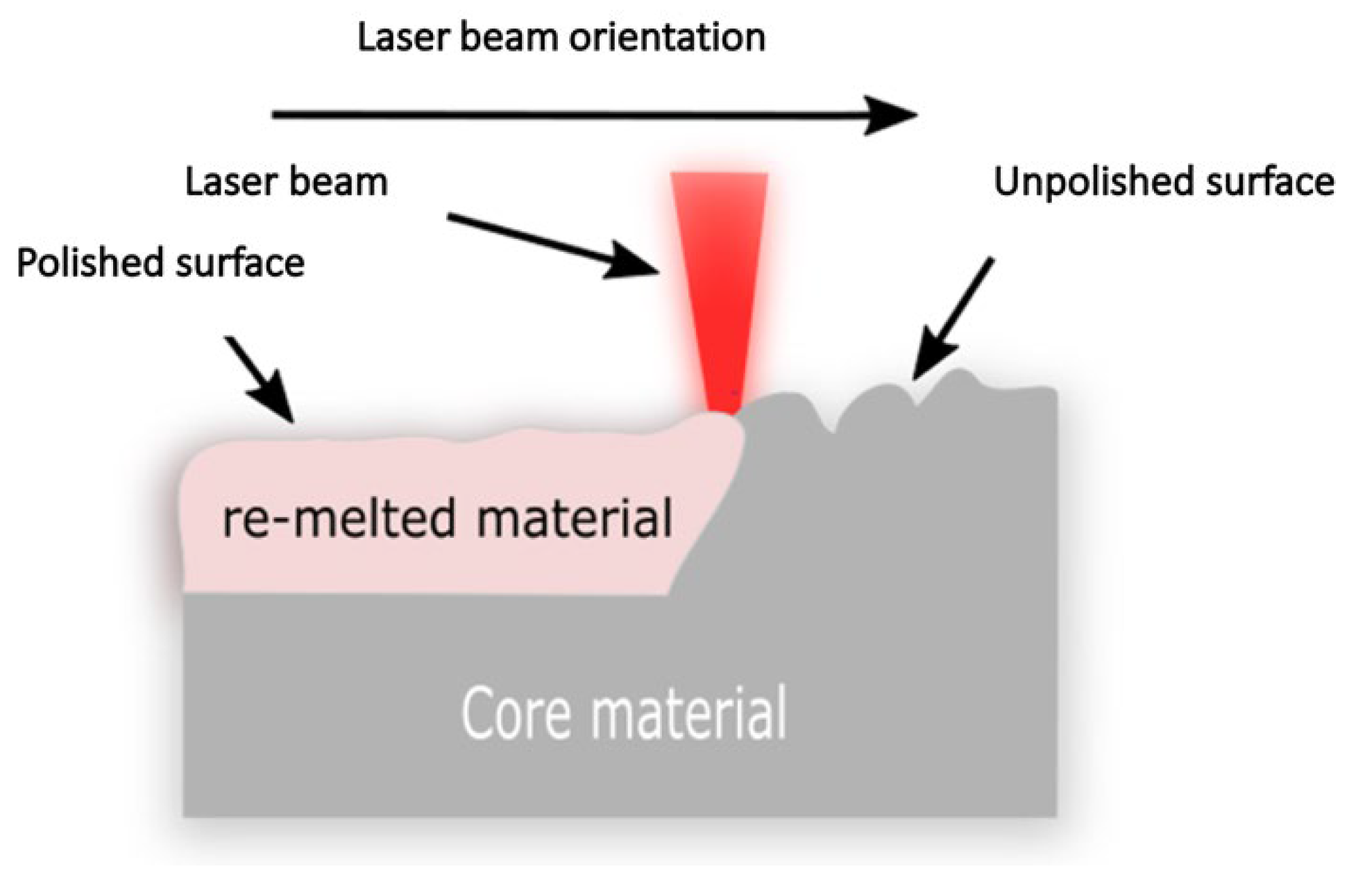
Figure 1.
Schematic of the laser polishing process and its parameters.

Figure 2.
Laser re-melting mechanism.

Figure 3.
Microstructure of Ti6Al4V. (a) as built; (b) after laser polishing. B.d. = build direction [41].
Figure 3.
Microstructure of Ti6Al4V. (a) as built; (b) after laser polishing. B.d. = build direction [41].

Figure 4.
Effect of different polishing process parameters on sample surface roughness (a) laser power P = 150 W, scanning pitch S = 0.1 mm, (b) scanning speed V = 40 mm/s, scanning pitch S = 0.1 mm for Ti, (c) laser power P = 150 W, velocity V = 40 mm/s [26].
Figure 4.
Effect of different polishing process parameters on sample surface roughness (a) laser power P = 150 W, scanning pitch S = 0.1 mm, (b) scanning speed V = 40 mm/s, scanning pitch S = 0.1 mm for Ti, (c) laser power P = 150 W, velocity V = 40 mm/s [26].

Figure 5.
(left): Relationship between energy density and roughness reduction rate for Ti6Al4V, (right): Initial and polished surface 1: (Power 100 W, feed rate 0.5 m/s), 2: (Power 100 W, feed rate 1 m/s), 3: (Power 200 W, feed rate 0.5 m/s), 4: (Power 200 W, feed rate 1 m/s), 5: (N0), 6: Power3100 W, feed rate 0.5 m/s), 7: (Power 300 W, feed rate 1 m/s), 8: (Power 400 W, feed rate 0.5 m/s), 9: (Power 400 W, feed rate 1 m/s) [48].

Figure 6.
Comparison of the areal average roughness (Sa) reduction after applying LP under the effect of the air and argon atmospheres [62].
Figure 6.
Comparison of the areal average roughness (Sa) reduction after applying LP under the effect of the air and argon atmospheres [62].

Figure 7.
S–N curves for polished and as-built batches [62].
Figure 7.
S–N curves for polished and as-built batches [62].

Figure 8.
Surface profiles unpolished and polished top side part [1].
Figure 8.
Surface profiles unpolished and polished top side part [1].

Figure 9.
HV values at various depths of the polished surface [15].
Figure 9.
HV values at various depths of the polished surface [15].

Figure 10.
Microhardness depth of LP parts in air and argon [87].
Figure 10.
Microhardness depth of LP parts in air and argon [87].

Figure 11.
Micro-hardness study [18].
Figure 11.
Micro-hardness study [18].

Figure 12.
The ANN concept for predicting surface quality: (a) topological network structure; (b) process optimization of the algorithms [100].
Figure 12.
The ANN concept for predicting surface quality: (a) topological network structure; (b) process optimization of the algorithms [100].

Figure 13.
Temperature contour of each image [102].
Figure 13.
Temperature contour of each image [102].

Figure 14.
Summary of the improvement in surface roughness of different AM materials after LP; [26] Li. K 2020, [46] Jaritngam 2020, [48] Zhang 2020, [47] Xiang 2018, [16] Zhihao 2018, [7] Dadbakhsh 2010, [62] Ćwikła 2018, [63] Koutiri 2018, [1] Gora 2016, [15] Yung 2018, [65] Wang 2018, [75] Dos Santos Solheid 2018, [85] Hofele 2017, [79] Li C. 2023, [80] Behjat 2023.


Table 1.
Laser polishing parameters and definitions.
| Parameters | Definition |
|---|---|
| Laser power PL | The optical power of the laser beam is measured in (W). It outputs a continuous beam (continuous wave) for macro-surface polishing or a discrete beam (pulsed mode) for micro-surface polishing. |
| Beam profile | Measuring intensity profile, including the radius and shape of the laser beam. The Gaussian beam profile is the most popular due to the intensity of the laser beam. |
| Laser beam diameter (dL) | The geometer of the laser beam that reflects on the surface of the workpiece. |
| Exposure time (dwelling time) tp | The pulse duration exposes a single spot on the surface workpiece. |
| Scanning speed vscan | The scanning speed of the laser beam is measured by a meter per second in continuing wave mode and measured by a point of distance over exposure time in pulsed mode. |
| Hatching distance | The distance between the center of two adjacent tracks. |
| Energy density (ED = Power (w)\(scanning speed (mm/s) × laser spot diameter (mm)) = J/mm3) | The energy over the three-dimensional volume includes the depth of penetration of the laser beam into the workpiece. It determines the required thermal input to the surface. An insufficient amount of laser energy density results in unmolten particles on the AM surface. |
| Linear energy density (E = Power (w)\linear speed (m/s) = J/m) | The scanning pattern of the laser beam on the workpiece. For example, 0°, 45°, and 90° along the X-axis. It could be scanned along the built-up tracks or at different angles. |
| Scan strategy | The scanning pattern of the laser beam on the workpiece. For example, 0°, 45°, and 90° along the X-axis. It can be scanned along the built-up tracks or at different angles. |
| Angle of incidence (ß) | The angle between the laser beam vector and the surface vector. |
| Scanning vector length | The length of the laser track that is polished. |
Table 2.
Comparison between simulated and experimental values of molten pool depth and width [26].
Table 2.
Comparison between simulated and experimental values of molten pool depth and width [26].
| Laser Heating Time (ms) | Simulate Depth (μm) | Experimental Depth (μm) | Error (%) | Simulate Width (μm) | Experimental Width (μm) | Error (%) |
|---|---|---|---|---|---|---|
| 0.8 | 51 | 54.7 | 7.3 | 270 | 331.9 | 18.6 |
| 1.2 | 66 | 70.7 | 7.1 | 310 | 366.9 | 18.4 |
| 1.6 | 83 | 89.5 | 7.8 | 360 | 435.8 | 21.1 |
Table 3.
Comparison between laser-polished and as-built samples of titanium.
| Reference | Sample As Received | Sample After Laser Polishing | Investigation | ||||
|---|---|---|---|---|---|---|---|
| Hardness Top Layer (Vickers) | Hardness Middle Layer (Vickers) | Wear Resistance | Hardness Top Layer (Vickers) | Hardness Middle Layer (Vickers) | Wear Resistance | ||
| [37] | 340 | N/A | Corrosion potential: 0.286 V corrosion current density: 7.718 μA/cm2 | 426 HV | N/A | Corrosion potential: 0.173 V corrosion current density: 6.29 μA/cm2 | Surface roughness in the laser macro-polishing process |
| [38] | 340 | N/A | N/A | 426 HV | N/A | Enhanced by 39% | Surface topography, solidification microstructure, and mechanical performance |
| [39] | 340 | 330 at a depth of 120 µm | N/A | 445 HV | 33 at a depth of 120 µm | N/A | LP influences the surface morphology, mechanical properties, and biocompatibility of the material elements. |
Table 4.
Laser process parameters for titanium.
| Reference | Laser Power | Scanning Speed | Overlap with Spot Size | Energy Density | Fabrication Method | Laser Beam Radius | Layer Thickness (Build-Up) | Laser Type and Mode | Roughness Reduction |
|---|---|---|---|---|---|---|---|---|---|
| [1] | 40 W | N/A | 75% (80 μm) | 7.1 kJ/cm2 | SLM | N/A | 30 μm | Fiber (CW) | 85% (111.7 nm) |
| [26] | 150 W | 40 mm/s | Pitch: 0.1 mm | N/A | SLM | 0.135 mm | N/A | Fiber (CW) | 60% (1.27μm) |
| [39] | 100 W | 300 mm/s | 400 μm spot size with 30 μm line spacing | N/A | N/A | N/A | N/A | N/A | 75% 0.51 μm |
| [48] | 400 W | 0.5 m/s | N/A | N/A | SLM | N/A | N/A | N/A | 62.3% |
| [51] | Repetition rate of 100 kHz the pulse duration of 224 fs | 20 mm/s | 85% | Laser fluences 32.8 J/cm2 | Femtosecond laser | 29 μm | N/A | Yb: KGW laser (pulse) | 16.6% (1.381 μm) |
| [36] | 70, 80, 90, 100 W | 50, 100, 150, 200, 250 mm/s | 10% | 7.1 kJ/cm2 | N/A | N/A | 30 μm | Fiber (CW) | 85% |
| [40] | 250 W | 750 mm/s | a hatch spacing of 50 μm. | N/A | N/A | N/A | 60 μm | N/A | 4 μm |
| [54] | 75, 125, 175 W | 200, 300, 400 mm/s | 25, 50, 75% | 3, 3.4, 3.6 J/mm2 | N/A | N/A | 60 μm | CO2 laser | 90% |
| [47] | 100,200,300,400 W | 0.5 and 1 m/s | N/A | N/A | N/A | N/A | 50 µm | Fiber (CW) | 62.3% |
Table 5.
Laser process parameters for Inconel.
| Reference | Laser Power | Scanning Speed | Overlap with Spot Size | Energy Density | Fabrication Method | Laser Beam Radius | Layer Thickness (Build-Up) | Laser Type and Mode | Roughness Reduction |
|---|---|---|---|---|---|---|---|---|---|
| [7] | 500 W | 800–850 mm/min | 35% | N/A | LMD | 0.7 mm | N/A | CO2 laser | Initial = 9.85 μm Polished = 2 μm |
| [16] | 90 W | 150 mm/s | 10% | N/A | SLM | Pulse duration: tP = 12–500 ns; spot diameter: 50 μm | N/A | AA nanosecond pulsed fiber laser | Initial = 7 μm Polished = 0.1 μm |
| [62] | 160 W | 150 mm/s | 90% | 177.78 J/mm2 | SLM | 0.6 mm | 30 μm | CW fiber laser | Polished = 87.9% |
| [63] | 180 W | 0.5 m/s | Tilt angles θ (10°) | 93.6 J/mm3 | SLM | 70 μm | N/A | CW fiber laser | 5.9 µm |
| [48] | 400 W | 0.5 m/s | Hatch 140 µm | 200 J/mm3 | SLM | N/A | 50 µm | N/A | Initial = 15 μm Polished = 3 μm |
Table 6.
Laser-polishing parameters for cobalt chromium.
| Reference | Laser Power | Scanning Speed | Object Distance | Energy Density | Fabrication Method | Laser Beam Radius | Laser Type and Mode | Roughness Reduction |
|---|---|---|---|---|---|---|---|---|
| [15] | 70 W | 300 mm/s | N/A | 8 J/mm2 | SLM | 50 µm | Pulse | 4.23 µm |
| [65] | 400 W | 500 mm/s | 208 mm | N/A | SLM | 50 µm | Pulsed fiber laser | N/A |
| [66] | 70 W | 500 mm/s | 216 mm | N/A | SLM | 50 µm | Pulse | N/A |
Table 7.
Scanning methods [93].
Table 7.
Scanning methods [93].
| Scanning Strategy | Microhardness (HV) | YS (MPa) UTS | UTS (MPa) | El (%) |
|---|---|---|---|---|
| X | 380 ± 7 | 720 ± 7 720 ± 7 | 1021 ± 28.19 (1001–1040) | 19 ± 0.70 (18.5–19.5) |
| XY | 399 ± 4 | 753 ± 10 (742–762) | 1082 ± 62 (1032–1152) | 17.5 ± 1.0 (16.4–18.3) |
| Wrought | - | 760–895 | 1000–1170 | 6–17 |
Table 8.
Laser-polishing parameters for steel.
| Reference | Laser Power | Scanning Speed | Object Distance | Energy Density | Fabrication Method | Laser Beam Radius | Laser Type and Mode | Roughness Reduction |
|---|---|---|---|---|---|---|---|---|
| [75] | 5–30 W (CW) 5–25 W (P) | 10–500 mm/s (CW) 25–2000 (P) | N/A | N/A | EOS M270 | 100 μm | CW and Pulse (duration 200 ns) | 0.7 μm |
| [76] | 150 W | 400 mm/s | N/A | N/A | N/A | 150 μm | pulsed fiber laser (IPG YLR-500-AC) | 0.190 μm |
| [83] | 400 W | 1000 mm/s | 1 mm, 2 mm, and 4 mm | N/A | ‘Q-switched’ | 250 μm | Pulsed with frequency 20 kHz | 0.1 μm |
| [85] | 1800 W | 50 mm/min | 2 mm | N/A | N/A | 110 μm | Pulsed with 1000 Hz | 0.35 μm |
Disclaimer/Publisher’s Note: The statements, opinions and data contained in all publications are solely those of the individual author(s) and contributor(s) and not of MDPI and/or the editor(s). MDPI and/or the editor(s) disclaim responsibility for any injury to people or property resulting from any ideas, methods, instructions or products referred to in the content. |
© 2023 by the authors. Licensee MDPI, Basel, Switzerland. This article is an open access article distributed under the terms and conditions of the Creative Commons Attribution (CC BY) license (https://creativecommons.org/licenses/by/4.0/).
Share and Cite
MDPI and ACS Style
Ali, M.; Almotari, A.; Algamal, A.; Qattawi, A. Recent Advancements in Post Processing of Additively Manufactured Metals Using Laser Polishing. J. Manuf. Mater. Process. 2023, 7, 115. https://doi.org/10.3390/jmmp7030115
AMA Style
Ali M, Almotari A, Algamal A, Qattawi A. Recent Advancements in Post Processing of Additively Manufactured Metals Using Laser Polishing. Journal of Manufacturing and Materials Processing. 2023; 7(3):115. https://doi.org/10.3390/jmmp7030115
Chicago/Turabian StyleAli, Majed, Abdalmageed Almotari, Anwar Algamal, and Ala Qattawi. 2023. "Recent Advancements in Post Processing of Additively Manufactured Metals Using Laser Polishing" Journal of Manufacturing and Materials Processing 7, no. 3: 115. https://doi.org/10.3390/jmmp7030115