Article

Selection of Welding Conditions for Achieving Both a High Efficiency and Low Heat Input for Hot-Wire Gas Metal Arc Welding

1
Graduate School of Advanced Science and Engineering, Hiroshima University, Higashi-Hiroshima 739-0046, Japan
2
Hitachi Construction Machinery Co., Ltd., Ibaraki 300-0013, Japan
*
Authors to whom correspondence should be addressed.
J. Manuf. Mater. Process. 2024, 8(2), 82; https://doi.org/10.3390/jmmp8020082
Submission received: 22 March 2024 / Revised: 13 April 2024 / Accepted: 17 April 2024 / Published: 18 April 2024

Abstract

:
This study presents a new gas metal arc welding (GMAW) technique that achieves both high efficiency and low heat input using a hybridization of the hot-wire method. The optimal combination of welding speed and welding current conditions was investigated using a fixed hot-wire feeding speed of 10 m/min on a butt joint with a V-shaped groove using 19 mm thick steel plates. Molten pool stability and defect formation were observed using high-speed imaging and cross-sectional observations. The power consumption and heat input were predicted prior to welding and measured in the experiments. The results indicate that a combination of a welding current of 350–500 A and welding speed of 0.3–0.7 m/min is optimal to avoid defect formation and molten metal precedence using three or four passes. The higher efficiency and lower heat input achieved by hot-wire GMAW results in a weld metal of adequate hardness, narrower heat-affected zone, smaller grain size at the fusion boundary, and lower power consumption than those obtained using tandem GMAW and high-current GMAW. Based on the experimental results, a single bevel groove, which is widely used in construction machinery welding joints, was welded using hot-wire GMAW, and we confirmed that the welding part could be welded in six passes, whereas eight passes were required with GMAW only.

1. Introduction

There is a strong demand in the construction machinery industry for improved welding productivity owing to the widespread use of thick steel plates [1]. Gas metal arc welding (GMAW) using a gas mixture of Ar + CO2 is mainly applied for joining steel plates. New processes have been developed and operating conditions have been optimized to improve the welding efficiency. For example, tandem GMAW [2,3,4,5,6] and high-current GMAW [7,8,9,10] have been developed and applied as high-efficiency welding processes. However, although these approaches can obtain higher efficiency (i.e., higher deposition rates) than conventional GMAW, they also require a considerably higher heat input, which deteriorates the joint properties (e.g., strength, toughness), especially in the heat-affected zone (HAZ). Tandem GMAW faces additional problems such as difficulties in welding condition optimization and low tolerance on actual construction sites.
Welding processes that involve a hybridization of the hot-wire method (e.g., gas tungsten arc welding (GTAW), GMAW, submerged arc welding, laser welding) have been investigated and applied to improve productivity in fields beyond the construction machinery industry [11,12,13,14,15,16,17,18,19,20,21,22]. The welding phenomena and optimization of hot-wire feeding conditions have been investigated for the GTAW process [23]. Previous studies suggested that the hot-wire current must be controlled to heat the tip immediately below its melting point, to achieve stable hot-wire feeding and stable welding phenomena. The hot-wire feeding speed can also be independently controlled from the main heat source. A combination of hot-wire feeding and welding processes is expected to have the potential to achieve both a high efficiency and low heat input because Joule heating is only used for heating the hot wire and not the arc, which creates a large heat input for base metal melting.
The purpose of this study was to develop a GMAW process in combination with hot-wire feeding to achieve both a high efficiency and low heat input. The optimal combination of welding speed and welding current conditions was investigated using a fixed hot-wire feeding speed of 10 m/min on a butt joint with a V-shaped groove using 19 mm thick steel plates. Molten pool stability and defect formation were observed using high-speed imaging and cross-sectional observations. The power consumption and heat input were predicted prior to welding and experimentally measured. The optimal combination of welding conditions was determined to avoid the presence of defects and achieve stable molten pool formation and hot-wire feeding using three or four passes. The welding efficiency, power consumption, and HAZ grain size were also compared with those produced using the tandem GMAW and high-current GMAW methods. To confirm the effectiveness of hot-wire GMAW in improving construction efficiency, welding was conducted on a single bevel with a plate thickness of 40 mm and a root face of 20 mm, which is widely used in the welding of construction machinery [24], using only GMAW and welding with hot-wire GMAW, and the welding efficiencies were compared. The shape of the weld toe has a significant influence on the fatigue strength in such T-joints [25]. Therefore, to control the bead shape, hot-wire was used only for welding inside the groove, and GMAW was used for welding outside the groove.

2. Materials and Methods

2.1. Material

Plates of 400 MPa-class steel (JIS SS400, produced by JFE Steel Co., Chiba, Japan) with 19 mm thickness were used as the base metal. A butt joint with a V-shaped groove, angle of 30°, and root gap of 4 mm was used, as shown in Figure 1. Filler wire (JIS Z3312 YGW-15, ZO-27 produced by KISWEL, Seoul, Republic of Korea) with a diameter of 1.4 mm was used for both the GMAW and hot-wire feeding. The same filler wire was also used for high-current GMAW, whereas filler wire (JIS Z3312 YGW-11, KC-26 produced by KISWEL, Republic of Korea) with a diameter of 1.2 mm was used for tandem GMAW. Plates of 490 MPa-class steel (JIS SM490A, produced by JFE Steel Co., Chiba, Japan) with a thickness of 45 mm and a root face of 20 mm, as shown in Figure 2, were applied to weld the single bevels used for a comparison with the improved welding efficiency of hot-wire GMAW.

2.2. Experimental Procedure

A schematic diagram of the experimental set-up for hot-wire GMAW is shown in Figure 3, and the welding conditions are listed in Table 1 and Table 2. A HITACHI DSP DIGITAL500RE (HITACHI, Ibaraki, Japan) welder was used and a Babcock-Hitachi IV1320 hot-wire power supply. A mixture of 80% Ar–20% CO2 was used as the shielding gas, which flowed from the GMA torch for shielding. The GMA torch and hot-wire torch were fixed to the arm, and welding was performed by moving the table on which the specimen was fixed. One pass was performed per welding layer. The first pass was welded by GMAW without hot-wire feeding using a welding speed of 0.3 m/min, arc current of 350 A, and weaving width of 2.5 mm, as listed in Table 1. Hot-wire GMAW was applied from the second to the fifth passes using a fixed hot-wire feeding speed of 10 m/min and hot-wire current of 234 A, as listed in Table 2. The hot wire was inserted 7 mm back from the torch of the GMA in all experiments. The weaving width of each pass was adjusted on the basis of the bead width of the previous pass. The welding speed and arc current were varied from 0.2 to 0.8 m/min and from 350 to 500 A, respectively, and 21 combinations of welding conditions were performed using hot-wire GMAW.
High-efficiency tandem GMAW and high-current GMAW processes were also performed to compare with hot-wire GMAW regarding the HAZ structure, power consumption, and welding efficiency. The first pass was welded using conventional single GMAW with an arc current of 350 A and welding speed of 0.3 m/min to avoid defects (i.e., same conditions as the hot-wire, tandem, and high-current GMAW processes). Arc currents of 330 and 300 A were applied, respectively, for the leading and trailing electrodes using tandem GMAW on the second pass with a welding speed of 0.34 m/min. An arc current of 500 A was applied for high-current GMAW on the second pass using a welding speed of 0.33 m/min. The welding conditions of both the tandem and high-current GMAW methods were chosen to minimize the excess weld metal volume and heat input.
The weld beads were evaluated in terms of their appearance, cross-sectional features, HAZ width, microstructure in the HAZ, and weld metal hardness. Observations of the weld microstructure were made by polishing the cut cross-section and then corroding it with a 1% concentration of nital. The HAZ width was measured at the center of the second pass because the same weaving width was applied in the second pass in all of the welding processes. The Vickers hardness of the weld metal was measured in a region without reheating effects on the final pass.
High-speed imaging was performed to observe and evaluate the stabilities of the arc, molten pool, and hot-wire feeding during welding. A nac RX-6 high-speed camera was used, which is compact and can capture images from a position where welding phenomena can be easily observed. The imaging conditions included a frame rate of 500 fps and shutter speed of 1/1000 s using a 980 nm bandpass filter without external lighting. The arc time, power consumption, heat input, and deposited metal volume were calculated and used to determine the highest efficiency and lowest heat input conditions. The power consumption and heat input were calculated from the measured current and voltage of both the GMAW and hot-wire GMAW.
The welding efficiency of hot-wire GMAW was compared with that of GMAW by welding a single-bevel T-joint. In welding conducted by hot-wire GMAW, hot wire was used in the second, third, and fifth passes to avoid defects such as molten-pool leading, which will be explained later, while the other 1, 4, and 6 passes were welded by only GMAW. Table 3 shows the welding conditions for GMAW, and Table 4 shows the welding conditions for hot-wire GMAW.

3. Results and Discussion

3.1. Welding Phenomena and Optimal Welding Conditions for Hot-Wire GMAW

The stabilities of the molten pool and hot-wire feeding during hot-wire GMAW were evaluated using high-speed images. Images captured under optimal conditions with an arc current of 350 A and welding speed of 0.4 m/min on the second and third passes are shown in Figure 4. The high-speed images were taken from the rear of the molten pool and show the continuous stabilities of the hot-wire feeding and molten pool formation.
Figure 5 shows the evaluated results of the relationship between the welding speed and arc current based on the high-speed images. The numbers 2–6 with boundary lines in Figure 5 indicate the calculated number of passes required to fill the groove for each combination of arc current (GMAW wire feeding speed) and welding speed. The adequate conditions are indicated as circles (○) in Figure 5, and the region where stable welding phenomena were observed is shown in red. The cross (× symbols in Figure 5 indicate inadequate conditions with a flow of molten metal preceding the molten pool (referred to as molten metal precedence) during welding. Molten metal precedence occurred under conditions involving lower welding speeds and higher arc currents. This implies that a larger molten metal volume and higher molten pool height lead to molten metal precedence. Molten metal precedence tends to cause a lack of fusion on the molten pool bottom and an irregular concave bead shape. The diamond (◇) symbols in Figure 5 indicate inadequate conditions with unstable hot-wire feeding. The hot-wire tip was heated by Joule heating to immediately below its melting point. The tip was melted only by the heat of the molten pool because the hot-wire feeding point was approximately 10 mm from the arc center. The combination of a higher welding speed and lower arc current did not create a sufficient molten pool volume and depth at the tail for stably melting the hot-wire tip with a relatively high feeding speed of 10 m/min. The triangle (△) symbols in Figure 5 indicate inadequate conditions with unstable melting and bead creation at both bead edges. Irregular melting of the base metal at both bead edges caused by an excessively high welding speed, compared with the oscillation frequency under 3 Hz, resulted in unstable melting and improper bead formation.
Figure 6 shows examples of the cross-sections welded using an arc current of 350 or 500 A at a variety of welding speeds. An imperfection is clearly visible at the boundary between the first and second passes on the cross-section under conditions of 350 A and 0.2 m/min, as shown in Figure 6a. This imperfection was formed by molten metal precedence, as described in Figure 5. The sound bead cross-sections in Figure 6b,c were formed using welding speeds of 0.3 and 0.5 m/min. A higher welding speed of 0.6 m/min also formed an imperfection at the bead edge on the final pass near the plate surface. This imperfection was caused by unstable hot-wire feeding under a combination of a higher welding speed (0.6 m/min) and lower arc current (350 A), as shown in Figure 5. Although molten metal precedence was observed (Figure 5), a sound defect-free cross-section was obtained under conditions of 500 A and 0.4 m/min, as shown in Figure 6c. A sound cross-section was also obtained under conditions of 450 A and 0.3 m/min. However, molten metal precedence has a high risk of forming an imperfection at the molten pool bottom on the boundary between passes. The sound beads can be observed in the cross-sections in Figure 6f,g using welding speeds of 0.5 and 0.7 m/min. A higher welding speed of 0.8 m/min formed a large imperfection at the bead edge on the final pass near the plate surface. This imperfection was caused by unstable melting and improper bead formation owing to the excessively high welding speed compared with the oscillation frequency described in Figure 5. The same imperfection was observed in the cross-sections of the beads formed under conditions of 400 A and 0.7 m/min and of 450 A and 0.8 m/min.

3.2. Effects of Arc Current and Welding Speed on the Joint Properties and Power Consumption

Figure 7 shows the HAZ width measured at the second pass center as contour colors based on the relationship between arc current and welding speed. The welding speed is found to strongly affect the HAZ width, whereas the arc current has a very small effect. However, the HAZ width is 1.5 mm even under welding conditions with a high heat affect, indicating that hot-wire GMAW has a very small heat effect compared to conventional welding methods. A narrow HAZ width (<1.2 mm) can be achieved even for welding speeds of 0.4–0.5 m/min to achieve stable welding and a defect-free joint.
Figure 8 shows the weld metal hardness measured at the final pass as contour colors based on the relationship between the arc current and welding speed. A combination of a lower arc current and higher welding speed was found to produce higher weld metal hardness values. Figure 9 shows the relationship between the weld metal hardness and heat input calculated from the measured current and voltage of GMAW and hot-wire feeding. Heat input was calculated from current and voltage values obtained from measurements at a sampling frequency of 5000 Hz from instruments attached to the GMAW and hot-wire GMAW, as shown in Figure 10. The heat input linearly affects the weld metal hardness. The combination of a higher arc current and higher welding speed induces a higher heat input and lower weld metal hardness. The heat input from hot-wire GMAW is also considerably smaller than that from GMAW because the hot-wire voltage is much smaller.
Figure 11 shows the power consumption per centimeter calculated from the measured current and voltage of the GMAW and hot-wire feeding as contour colors based on the relationship between the arc current and welding speed. A combination of a lower arc current and higher welding speed can reduce the power consumption under both the third- and fourth-pass conditions. The selectable region of welding conditions, therefore, widens to achieve a narrower HAZ, higher weld metal hardness, lower heat input, lower power consumption, and smaller pass numbers by combining hot-wire feeding with GMAW.

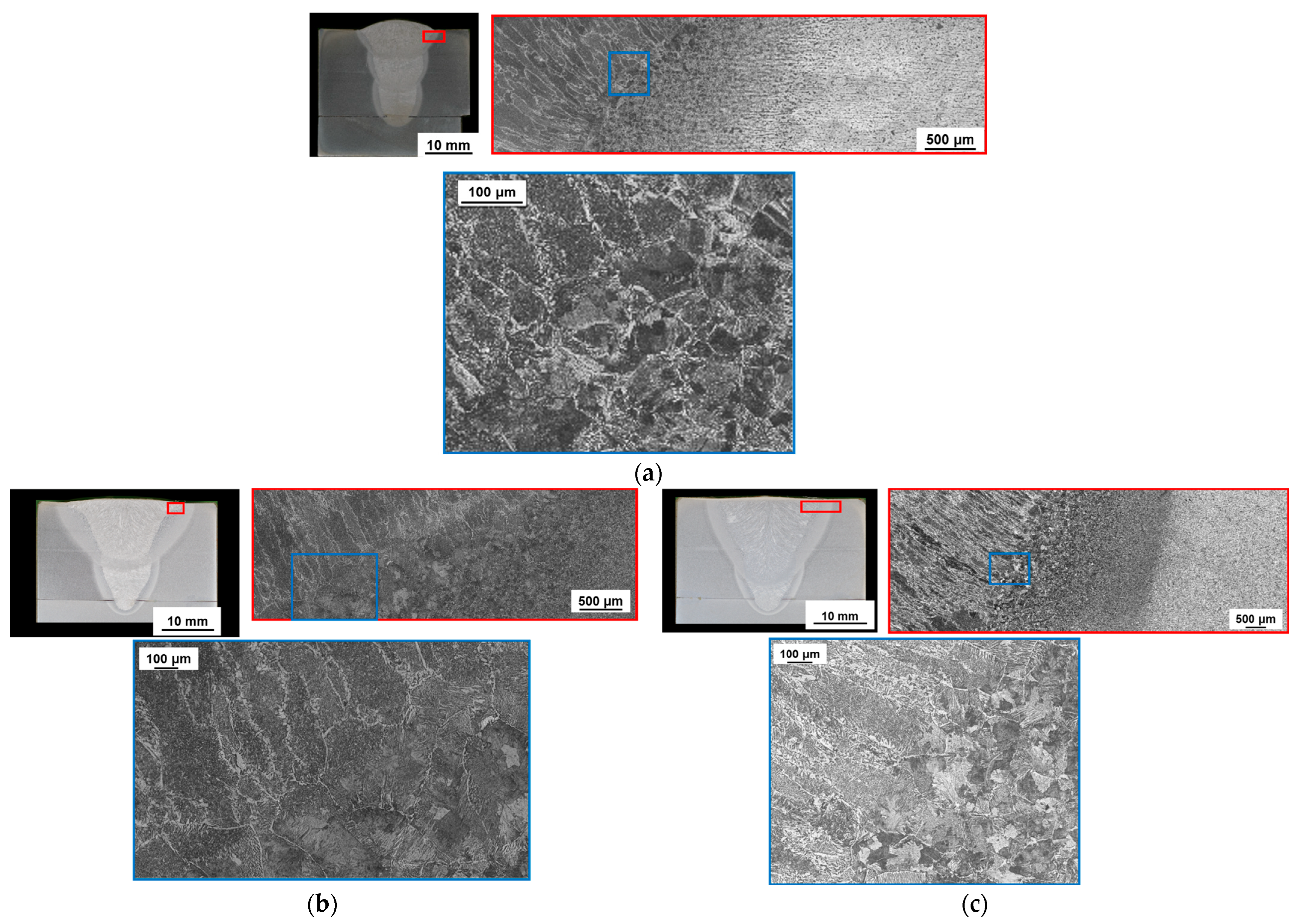
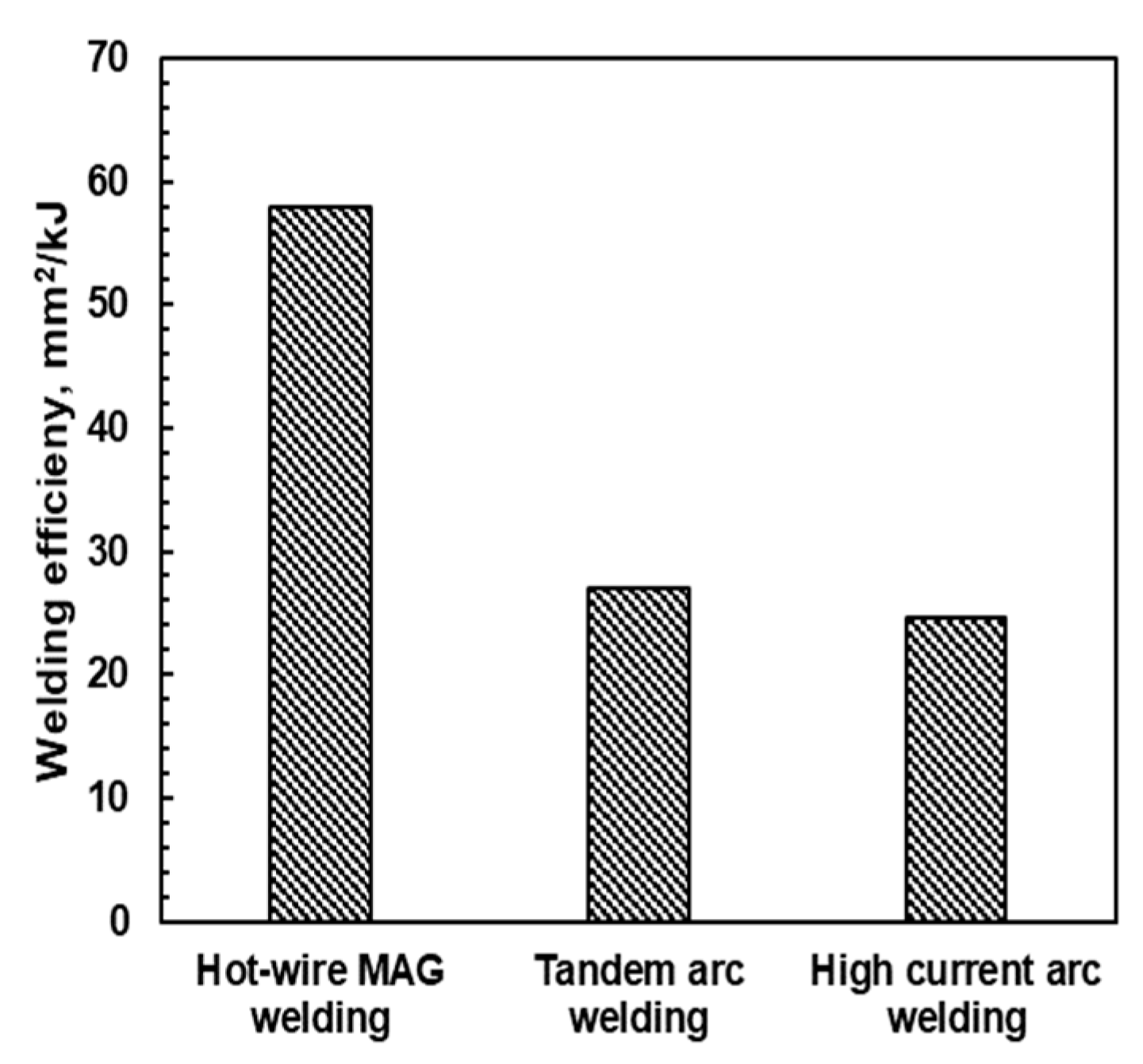
3.3. Comparison of HAZ Properties and Welding Efficiency with Other Welding Processes

Micrographs of the welded joints of hot-wire GMAW (arc current = 350 A, welding speed = 0.4 m/min), tandem GMAW, and high-current GMAW were observed and compared. Figure 12 shows cross-sectional photographs of the welded joints using each welding method. The grain sizes at the fusion boundary obtained using hot-wire, tandem, and high-current GMAW are approximately 100, 500, and 400 μm, respectively. The heat input is the most influential factor for grain coarsening at the HAZ fusion boundary. A lower heat input achieves a smaller grain size. However, it is difficult for conventional GMAW processes to suppress grain coarsening because the heat input must increase to achieve higher efficiency (i.e., a higher deposition rate), whereas the application of hot-wire GMAW can effectively suppress grain coarsening. The cooling rate is the largest factor in preventing grain coarsening in the heat-affected zone, and the holding time in the austenite growth temperature range should be kept as short as possible. In tandem arc welding, a two-electrode arc is used and the molten pool shape becomes very long in the welding direction, making it difficult to increase the cooling rate. In addition, the welding speed must be increased to speed up the cooling rate in high-current arc welding, but it is difficult to increase the welding speed when the stability of the molten pool is considered. Therefore, hot-wire GMAW is effective for both suppressing grain coarsening in the heat-affected zone and achieving high efficiency.
The deposited groove area was filled using a heat input of 1 kJ in the three welding processes and calculated to quantitatively evaluate the welding efficiency. The welding efficiency was calculated from the wire feeding speed. The wire feeding measurement equipment was attached to the wire feeding equipment, and the welding efficiency was calculated using the measurement result. Figure 13 shows the calculated results of each welding process. Hot-wire GMAW clearly achieves more than twice the welding efficiency of that obtained using tandem GMAW and high-current GMAW. Hot-wire GMAW also allows a relatively high degree of freedom for the combination of welding conditions (e.g., welding speed, welding current), while maintaining a high level of deposition. This makes it possible to select specific process conditions for the designed purpose, such as to reduce the number of passes, increase the welding speed, improve the weld metal properties, and improve the HAZ properties.

3.4. Investigation of Improvement in Welding Efficiency with Hot-Wire Method

To confirm the improvement in welding efficiency by the hot-wire method, single-bevel joints were welded using hot-wire GMAW and GMAW. Figure 14 shows a cross-sectional picture of a welded joint using GMAW and hot-wire GMAW. Eight passes were required for the joint welded with GMAW, while six passes were required for the joint welded with hot-wire GMAW. Defect-free joints were welded by both welding methods. In the joints welded with hot-wire GMAW, the amount of weld metal increased in the second, third, and fifth passes where hot wire was added, but the heat-affected zone was small.
These results show that the welding efficiency can be improved even in single-bevel joints by using hot-wire GMAW under appropriate conditions, avoiding conditions where defects such as molten pool leading can occur.

4. Conclusions

In this study, the optimal welding conditions (welding speed and welding current) were investigated using a fixed hot-wire feeding speed of 10 m/min on a butt joint with a V-shaped groove and with 19 mm thick steel plates for hot-wire GMAW. Molten pool stability, hot-wire feeding stability, and defect formation were observed using high-speed imaging and cross-sectional observations. The welded joint properties of the HAZ width and weld metal hardness were evaluated, and the effect of each welding parameter was discussed. The HAZ width and welding efficiency were compared with those produced using tandem GMAW and high-current GMAW. Finally, hot-wire GMAW welding was conducted on a single-bevel joint, and it was confirmed that hot-wire GMAW had advantages over GMAW in terms of heat input and efficiency.
  • The optimal combination of welding conditions using hot-wire GMAW is a welding current of 350–500 A and welding speed of 0.3–0.7 m/min, which were derived to avoid defect formation and molten metal precedence using three or four passes.
  • The welding speed more dominantly affects the HAZ width and weld metal hardness than the welding current because hot-wire feeding produces large deposition while suppressing increased heat input.
  • Hot-wire GMAW can better suppress grain coarsening at the HAZ fusion boundary when compared with the conventional high-heat-input processes of tandem GMAW and high-current GMAW.
  • Hot-wire GMAW achieves a substantially higher welding efficiency (i.e., deposition volume/heat input) and lower power consumption than tandem GMAW and high-current GMAW.
  • Welding was conducted by GMAW and hot-wire GMAW on a single bevel with a 45 mm plate thickness and 20 mm root face, and in this experiment, welding was achieved in eight passes with GMAW and in six passes with hot-wire GMAW. These results confirm that hot-wire GMAW can improve the welding efficiency in welding processes not only for butt welding.
This research has clarified the factors causing defects in hot-wire GMAW in V-groove welding by visualization using a high-speed camera. In addition, compared to conventional high-efficiency welding methods, it has been shown that hot-wire GMAW has a high efficiency with a low heat input and has the potential to significantly improve the welding efficiency in the welding of thick plates. These research results will enable a significant improvement in the welding efficiency of large welded structures such as with shipbuilding, construction machinery, and plants.

Author Contributions

Conceptualization, K.M., A.F., T.T., H.Y. and M.Y.; methodology, K.M. and A.F.; validation, K.M.; formal analysis, K.M.; investigation, K.M. and A.F.; resources, A.F., T.T. and H.Y.; data curation, K.M. and A.F.; writing—original draft preparation, K.M.; writing—review and editing, K.M. and M.Y.; visualization, K.M.; supervision, T.T. and M.Y.; project administration, T.T. and M.Y.; funding acquisition, H.Y. and M.Y. All authors have read and agreed to the published version of the manuscript.

Funding

This research received no external funding.

Data Availability Statement

The original contributions presented in the study are included in the article, further inquiries can be directed to the corresponding author.

Acknowledgments

We express our sincere gratitude to Hajime Tamata for his invaluable contributions and support throughout this project.

Conflicts of Interest

Authors 2, 3 and 4 were employed by the company Hitachi Construction Machinery Co., Ltd., Japan. The remaining authors declare that the research was conducted in the absence of any commercial or financial relationships that could be construed as a potential conflict of interest.

References

  1. Yamamoto, H. Welding Technologies for Production of Construction Equipments. J. Jpn. Weld. Soc. 2007, 76, 35–38. [Google Scholar] [CrossRef]
  2. Okui, N.; Ohga, S.; Saitoh, T.; Suzuki, T.; Maki, S.; Honma, H. Study on High Speed Fillet Welding by Tandem Arc MAG Process. Q. J. Jpn. Weld. Soc. 2000, 18, 555–562. [Google Scholar] [CrossRef]
  3. Scalet Rossini, L.F.; Valenzuela Reyes, R.A.; Spinelli, J.E. Double-Wire Tandem GMAW Welding Process of HSLA50 Steel. J. Manuf. Process. 2019, 45, 227–233. [Google Scholar] [CrossRef]
  4. Häßler, M.; Rose, S.; Füssel, U. The Influence of Arc Interactions and a Central Filler Wire on Shielding Gas Flow in Tandem GMAW. Weld. World 2016, 60, 713–718. [Google Scholar] [CrossRef]
  5. Chen, D.; Chen, M.; Wu, C. Effects of Phase Difference on the Behavior of Arc and Weld Pool in Tandem P-GMAW. J. Mater. Process. Technol. 2015, 225, 45–55. [Google Scholar] [CrossRef]
  6. Yokota, M.; Kihata, S.; Nakao, T. Tandem Arc Welding System. Kobe Steel Eng. Rep. 2007, 54, 81–85. [Google Scholar]
  7. Baba, H.; Honda, R.; Era, T.; Komen, H.; Tanaka, M.; Terasaki, H. Microstructure Observation of High-Current Buried-Arc Welded Joint. Q. J. Jpn. Weld. Soc. 2020, 38, 11s–15s. [Google Scholar] [CrossRef]
  8. Baba, H.; Komen, H.; Igarashi, T.; Kadota, K.; Era, T.; Terasaki, H.; Tanaka, M. Stabilization of High-Current Buried-Arc Welding Using Large Diameter φ1.6mm Wire by Low-Frequency Modulated Voltage Control. Q. J. Jpn. Weld. Soc. 2021, 39, 75–86. [Google Scholar] [CrossRef]
  9. Baba, H.; Kadota, K.; Era, T.; Ueyama, T.; Maeshima, M.; Kadoi, K.; Inoue, H.; Tanaka, M. Single-Pass Full-Penetration Welding for Thick Stainless Steel Using High-Current GMAW. Q. J. Jpn. Weld. Soc. 2021, 39, 39–50. [Google Scholar] [CrossRef]
  10. Baba, H.; Era, T.; Ueyama, T.; Tanaka, M. Single Pass Full Penetration Joining for Heavy Plate Steel Using High Current GMA Process. Weld. World 2017, 61, 963–969. [Google Scholar] [CrossRef]
  11. Tsuyama, T.; Nakai, K.; Noumaru, K.; Sakamoto, T.; Kobayashi, S. Effect of Hot-Wire on Microstructure and Mechanical Property in Weld Metal Formed with CO2 Gas Shielded Arc Welding Method. Q. J. Jpn. Weld. Soc. 2013, 31, 104–111. [Google Scholar] [CrossRef]
  12. Tsuyama, T.; Nakai, K.; Akiyama, M.; Takahashi, B.; Sakamoto, T.; Kobayashi, S. Effects of Microstructure on Mechanical Property in Weld Metal Formed with the Hot-Wire Method Applying Ordinal CO2 Gas Shielded Arc Welding Method. Tetsu-Hagane 2013, 99, 468–474. [Google Scholar] [CrossRef]
  13. Spaniol, E.; Trautmann, M.; Ungethüm, T.; Hertel, M.; Füssel, U.; Henckell, P.; Bergmann, J.P. Development of a Highly Productive GMAW Hot Wire Process Using a Two-Dimensional Arc Deflection. Weld. World 2020, 64, 873–883. [Google Scholar] [CrossRef]
  14. Spaniol, E.; Ungethüm, T.; Trautmann, M.; Andrusch, K.; Hertel, M.; Füssel, U. Development of a Novel TIG Hot-Wire Process for Wire and Arc Additive Manufacturing. Weld. World 2020, 64, 1329–1340. [Google Scholar] [CrossRef]
  15. Ungethüm, T.; Spaniol, E.; Hertel, M.; Füssel, U. Analysis of Metal Transfer and Weld Geometry in Hot-Wire GTAW with Indirect Resistive Heating. Weld. World 2020, 64, 2109–2117. [Google Scholar] [CrossRef]
  16. Tsuyama, T.; Nakai, K.; Tsuji, T. Development of Submerged Arc Welding Method Using Hot Wire. Weld. World 2014, 58, 713–718. [Google Scholar] [CrossRef]
  17. Wonthaisong, S.; Shinohara, S.; Shinozaki, K.; Phaoniam, R.; Yamamoto, M. High-Efficiency and Low-Heat-Input CO2 Arc-Welding Technology for Butt Joint of Thick Steel Plate Using Hot Wire. Q. J. Jpn. Weld. Soc. 2020, 38, 164–170. [Google Scholar] [CrossRef]
  18. Suwannatee, N.; Wonthaisong, S.; Yamamoto, M.; Shinohara, S.; Phaoniam, R. Optimization of Welding Conditions for Hot-Wire GMAW with CO2 Shielding on Heavy-Thick Butt Joint. Weld. World 2022, 66, 833–844. [Google Scholar] [CrossRef]
  19. Kim, J.; Van, D.; Lee, J.; Yim, J.; Lee, S.H. The Effect of a Hot-Wire in the Tandem GMAW Process Ascertained by Developing a Multiphysics Simulation Model. J. Mech. Sci. Technol. 2021, 35, 267–273. [Google Scholar] [CrossRef]
  20. Suwannatee, N.; Yamamoto, M. Single-Pass Process of Square Butt Joints without Edge Preparation Using Hot-Wire Gas Metal Arc Welding. Metals 2023, 13, 1014. [Google Scholar] [CrossRef]
  21. Suwannatee, N.; Yamamoto, M.; Shinohara, S. Optimization of Hot-Wire Fraction for Enhance Quality in GMAW. Weld. World 2023. [Google Scholar] [CrossRef]
  22. Ungethüm, T.; Schilling, P.; Spaniol, E.; Füssel, U. GMAW Hot-Wire Process with Indirect Resistive Heating of the Auxiliary Wire. Weld. World 2023, 67, 2031–2038. [Google Scholar] [CrossRef]
  23. Shinozaki, K.; Yamamoto, M.; Mitsuhata, K.; Nagashima, T.; Kanazawa, T.; Arashin, H. Bead Formation and Wire Temperature Distribution during ULTRA-HIGH-SPEED GTA WELDING Using Pulse-Heated Hot-Wire. Weld. World 2011, 55, 12–18. [Google Scholar] [CrossRef]
  24. Onozuka, M.; Ushirokawa, O.; Kumakura, Y.; Tsuji, I. Stress Concentrations of the Bead Toe and Fatigue Life. J. Soc. Nav. Archit. Jpn. 1991, 1991, 693–703. [Google Scholar] [CrossRef]
  25. Takano, Y. Technical Information. Special Issue. The-State-of-the-Art and the Subjects of Arc Welding Automation in Construction Machine Industry. J. Jpn. Weld. Soc. 1993, 62, 448–454. [Google Scholar] [CrossRef]
Figure 1. V-groove specimen’s configuration (dimensions are in mm).
Jmmp 08 00082 g001
Figure 2. Single-bevel-groove T-joint specimen’s configuration (dimension are in mm).
Jmmp 08 00082 g002
Figure 3. Schematic illustration of experimental set-up.
Jmmp 08 00082 g003
Figure 4. High-speed images during hot-wire GMAW under adequate conditions: arc current of 350 A and welding speed of 0.4 m/min for the second and third passes; (a) 2nd layer; (b) 3rd layer.
Jmmp 08 00082 g004
Figure 5. Evaluated results of the molten pool and hot-wire feeding stabilities during hot-wire GMAW based on high-speed images. The number in the square indicates the number of passes required for welding, and the red area indicates the proper welding zone. (○: Stable; ×: Molten metal precedence; △: Insufficient weaving frequency; ◇: Unstable hot wire supply).
Jmmp 08 00082 g005
Figure 6. Bead cross-sections formed arc currents of 350 and 500 A: (a) 350 A, 0.2 m/min; (b) 350 A, 0.3 m/min; (c) 350 A, 0.5 m/min; (d) 350 A, 0.6 m/min; (e) 500 A, 0.4 m/min; (f) 500 A, 0.5 m/min; (g) 500 A, 0.7 m/min; (h) 500 A, 0.8 m/min.
Jmmp 08 00082 g006
Figure 7. HAZ width measured on the second pass. The number in the square indicates the number of passes required for welding. (○: Stable; ×: Molten metal precedence; △: Insufficient weaving frequency; ◇: Unstable hot wire supply).
Jmmp 08 00082 g007
Figure 8. Weld metal hardness measured on the final pass. The number in the square indicates the number of passes required for welding. (○: Stable; ×: Molten metal precedence; △: Insufficient weaving frequency; ◇: Unstable hot wire supply).
Jmmp 08 00082 g008
Figure 9. Relationship between weld metal hardness and heat input.
Jmmp 08 00082 g009
Figure 10. Measured voltage and current of GMAW and hot wire: (a) GMAW (350 A); (b) hot wire (234 A).
Jmmp 08 00082 g010
Figure 11. Power consumption during hot-wire GMAW. The number in the square indicates the number of passes required for welding, and the red area indicates the proper welding zone. (○: Stable; ×: Molten metal precedence; △: Insufficient weaving frequency; ◇: Unstable hot wire supply).
Jmmp 08 00082 g011
Figure 12. Cross-section and microstructure on the fusion boundary: (a) hot-wire GMAW; (b) tandem GMAW; (c) high-current GMAW.
Jmmp 08 00082 g012
Figure 13. Welding efficiency per unit heat input for three welding processes.
Jmmp 08 00082 g013
Figure 14. Single-bevel-groove T-joint weld bead cross-section pictures: (a) GMAW; (b) hot-wire GMAW.
Jmmp 08 00082 g014
Table 1. First-pass welding conditions for hot-wire GMA butt welding.
GMAW Conditions
Arc current, A350
Arc voltage, V27
Shielding gas, L/min25
Extension length, mm33
Weaving width, mm2.5
Table 2. Second~fifth-pass welding conditions for hot-wire GMA butt welding.
GMAW Conditions
Arc current, A350~500
Arc voltage, V27~36
Welding speed, m/min0.2~0.8
Shielding gas, L/min25
Extension length, mm33
Weaving width, mm2.5
Hot-wire Conditions
Wire current, A234
Wire feeding speed, m/min10
Power supply distance, mm75
Wire feeding position, mm7
Wire feeding angle, degree80
Table 3. GMA single-bevel-groove T-joint welding conditions.
GMAW Conditions
Arc current, A300~400
Arc voltage, V32~39
Welding speed, m/min0.22~0.42
Shielding gas, L/min25
Table 4. Hot-wire GMA single-bevel-groove T-joint welding conditions.
GMAW Conditions
Arc current, A320~500
Arc voltage, V32~39
Welding speed, m/min0.3~0.42
Shielding gas, L/min25
Hot-wire Conditions
Wire feeding speed, m/min10~15
Power supply distance, mm75
Wire feeding angle, degree45
Disclaimer/Publisher’s Note: The statements, opinions and data contained in all publications are solely those of the individual author(s) and contributor(s) and not of MDPI and/or the editor(s). MDPI and/or the editor(s) disclaim responsibility for any injury to people or property resulting from any ideas, methods, instructions or products referred to in the content.

