Article

Development of Pb-Free Nanocomposite Solder Alloys

1
Adelaide Microscopy, the University of Adelaide, Adelaide, SA 5005, Australia
2
Department of Mechanical Engineering, Curtin University, Bentley, WA 6845, Australia
3
Department of Materials Engineering, Isfahan University of Technology, Isfahan 83714, Iran
4
School of Mechanical Engineering, the University of Adelaide, Adelaide, SA 5005, Australia
*
Author to whom correspondence should be addressed.
J. Compos. Sci. 2018, 2(2), 28; https://doi.org/10.3390/jcs2020028
Submission received: 23 March 2018 / Revised: 12 April 2018 / Accepted: 16 April 2018 / Published: 20 April 2018

Abstract

:
As an alternative to conventional Pb-containing solder material, Sn–Ag–Cu (SAC) based alloys are at the forefront despite limitations associated with relatively poor strength and coarsening of grains/intermetallic compounds (IMCs) during aging/reflow. Accordingly, this study examines the improvement of properties of SAC alloys by incorporating nanoparticles in it. Two different types of nanoparticles were added in monolithic SAC alloy: (1) Al2O3 or (2) Fe and their effect on microstructure and thermal properties were investigated. Addition of Fe nanoparticles leads to the formation of FeSn2 IMCs alongside Ag3Sn and Cu6Sn5 from monolithic SAC alloy. Addition of Al2O3 nano-particles do not contribute to phase formation, however, remains dispersed along primary β-Sn grain boundaries and act as a grain refiner. As the addition of either Fe or Al2O3 nano-particles do not make any significant effect on thermal behavior, these reinforced nanocomposites are foreseen to provide better mechanical characteristics with respect to conventional monolithic SAC solder alloys.

1. Introduction

The expansion of electronic packaging system in the context of miniaturization requires a number of factors to be taken into consideration such as wafer design, resist system, metal deposition techniques etc. The most crucial among these factors is ‘soldering’, without which none of the electronic packaging is complete [1,2]. Soldering as a word doesn’t confine itself only in electronic industries, but also frequently used in plumbing (acid core) and sheet metal joining. Usually, the alloys that melt (using fluxing materials such as CaF2) within the 90–450 °C are termed solder materials [2]. However, for electronic packaging, the melting temperature of solder alloy remains within 170–190 °C [2]. Lead (Pb) based alloys have a long history as solder alloys and over past decades have been the most predominant solder alloy used. However, the environmental concern strictly prohibits the use of such toxic alloys paving the way for the development of Pb-free solder alloys. Usually, whenever a set of metals are mixed to form solder alloys, a number of facts come into consideration including cost compatibility, ease of fabrication, compliance with physical, chemical, mechanical and electrical properties with substrate and finally long term environmental sustainability. It is understood that solder materials in electronic packaging undergo thermal stress, not only during fabrication and reflowing, but also at service. Therefore, it is highly probable that this thermal stress renders the solder materials unsuitable under adverse condition where the possibility of metallurgical change is eminent. Thus, the applicability of a solder alloy is attributed to its resistance under low cycle thermal fatigue which is governed by its underlying microstructure.
To fulfil such requirements, Sn–Ag–Cu (Tin–Silver–Copper) based alloys provide a good alternative [1,2]; as this ternary alloy system yields comparable mechanical, thermal, creep and fatigue properties as that of conventional Pb-based solder alloys, thanks to its eutectic microstructure. The foreseen success of these alloys is due to intermetallic compounds (IMCs) formation such as Cu6.26Sn5 (hexagonal), Cu6Sn5 (monoclinic), Ag4Sn (hexagonal) and Ag3Sn (orthorhombic) in β-Sn (tetragonal) matrix that provide the mechanical strength while retaining comparatively low melting point and formability [3,4,5]. Based on nanoindentation it was reported that failure mode of Cu6Sn5 and Cu3Sn IMCs are brittle in nature in contrast of ductile mode failure of Ag3Sn [6]. The ternary SAC system was first reported in [7] and have quasi-eutectic composition of Sn-4Ag-0.5Cu. However, a number of compositional variation of these alloys has been reported [1,8,9]. Irrespective of near eutectic composition, these alloys contain IMCs dispersed in β-Sn matrix. As reported by Lehman et al. [10], mechanical durability of such alloy at service depends on relative orientation and microstructure formation of such IMCs in β-Sn matrix. It was observed that, single grained Sn joint in solder fails to balance repeated thermal stress, however, near eutectic SAC at 80 °C underwent cyclic growth twinning all through solidification process [9]. Reflowing of such SAC based solder on Cu substrate cause coarsening effect of IMCs and degrade mechanical properties. IMCs continues to grow at reflowing temperature within short period of time irrespective of SAC alloy composition. Discontinuity of such IMCs has many disadvantages such as lack of mechanical strength, failure in low magnitude thermal cycles etc. Therefore, with a view to improve mechanical property and service reliability of these solder alloys, incorporation of reinforcing elements is beneficial. Recent investigations on nanoparticles reinforced Al-matrix composite exhibits superior mechanical properties of materials [10] in terms of limiting grain growth, strength and avoid grain coarsening. Among these reinforcing elements NiO [11], Al2O3 [12], TiO2 [13], pure elements such as Ni, Fe, Bi [14,15] and even rare earth elements has been reported [16] to extent its mechanical properties further without compromising thermal behavior. Regardless of type reinforcing particles, overall objectives are matrix grain refinement, favors IMCs formation, retain alloy strength during service and restrict grain/IMCs growth during fabrication/reflowing. Though there are some reports published in literature on that, however, it’s still in very early stage of development and more fundamental work in that area is foreseen.
Thus, objective of the present work is to investigate the effect of nano-size Fe or Al2O3 addition in monolithic Sn-4.4Ag-2.6Cu alloy on its microstructure, phase evolution and thermal behavior. Towards that, an experimental based approach was adopted to make fundamental understating and further development of durable Pb-free solder nanocomposites.

2. Experimental

2.1. Materials

The common manufacturing processes for the fabrication of composite solders are usually casting or conventional powder metallurgy routes [12,17] followed by sintering. However, powder metallurgy routes following by sintering suffer from grain/IMCs growth and contain defects such as inhomogeneous microstructure due to agglomeration, segregation, gas trapping etc. To overcome that, casting method was employed in present case. A Pb-free Sn-4.4Ag-2.6Cu (wt %) solder alloy, hereby termed as SAC, was prepared by melting commercially pure (99.99%) tin, silver and copper metals in an induction furnace at about 1000 °C for 40 min under vacuum according to their nominal composition. Then the melt was cast in ingot form and re-melted again at 1000 °C for 20 min under vacuum for proper homogenization of the alloy. After that, either Al2O3 or Fe nanoparticles were added in monolithic SAC alloy to form nanocomposite solder alloys and subsequently, cast in to disk shaped ingots (Ø 30 mm, 2 mm thickness) and allowed to cool slowly to form ternary eutectic microstructure. Hereby, nanocomposite solder alloys reinforced with Fe is termed as SAC1 and nanocomposite solder alloy reinforced with Al2O3 is termed as SAC2. Al2O3 nanoparticles with an average particulate size of 50 nm and Fe with an average particulate size of 30 nm (as specified by the supplier, in both case) were obtained from Advanced Pinnacle Technologies, Singapore. The alumina content was 0.5 wt %, whereas Fe content was 2 wt %. The choice of Al2O3 nanoparticles was based on their relatively low density and high hardness, where Fe was added to favor IMCs formation. The samples were then cold mounted in epoxy resin and metallographic polishing was carried out in Struers Tegrapol (Struers, Sweden) automatic polisher with different size diamond slurry followed by final polishing in colloidal silica suspension.

2.2. Methodology

Microstructural characterization of solder alloys was carried out in FIB-SEM (Helios Nova lab 600, FEI) equipped with energy dispersive X-ray (EDX) system. Top-view SEM micrographs were taken after standard metallographic polishing as mentioned in Section 2.1 and FIB-SEM was used to mill out material to reveal cross-sectional view. To analyse the phases present in the alloy, X-ray diffraction (XRD) was carried using a monochromatic CuKα radiation (New D8 advance, Bruker, Germany). Thermal analysis of the alloys was carried out with thermogravimetric analysis and differential scanning calorimeter (TGA/DSC 2, Mettler Toledo, Columbus, OH, USA) in an inert atmosphere (Ar) with heating rate of 5 °C/min from 50 °C to 400 °C. 10 mg of the crushed (powdered) alloy was placed in alumina crucible inside the chamber. The system was computer controlled and provided real time data.

3. Result and Discussion

3.1. Microstructure of Solder Alloys

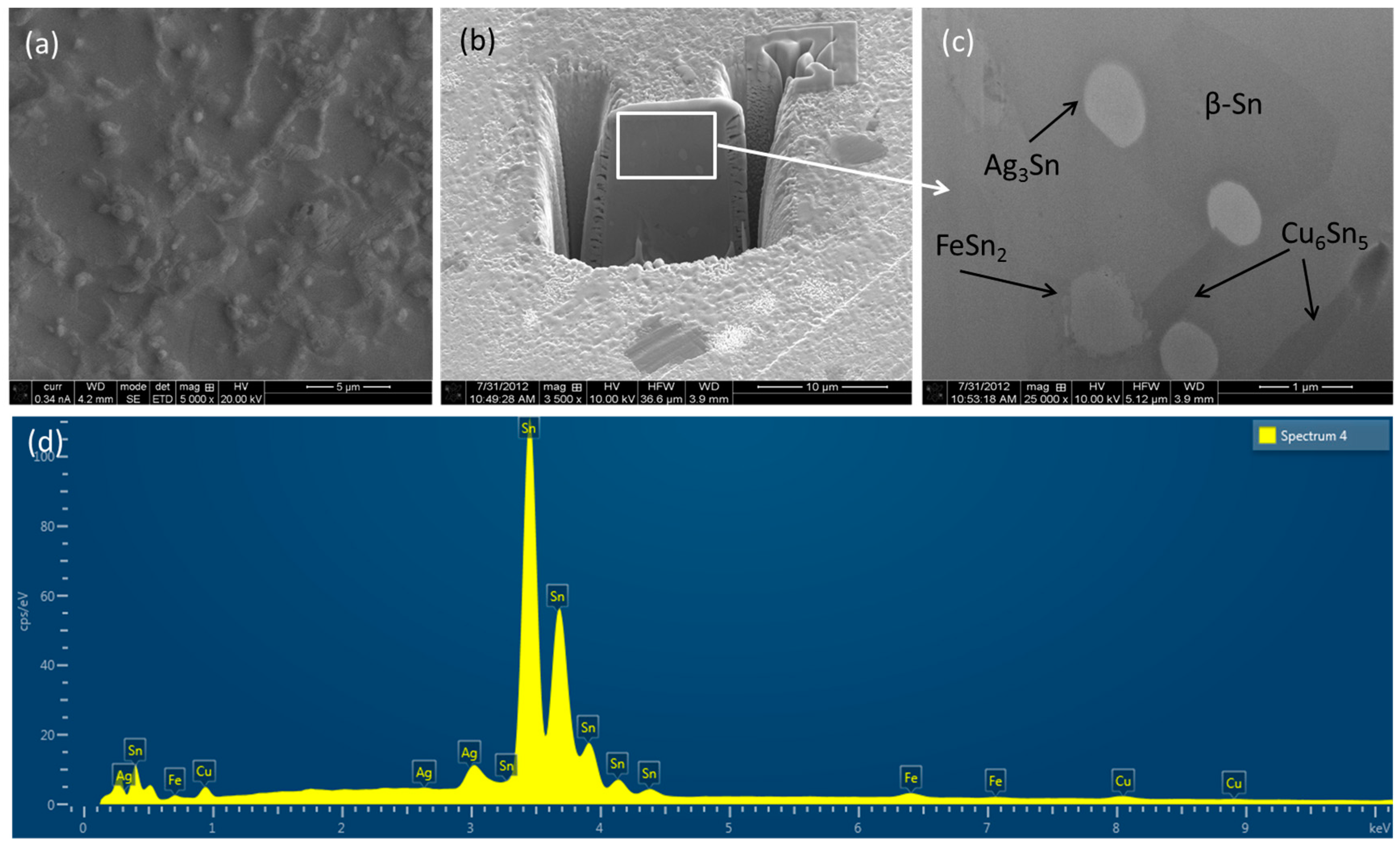
SEM micrographs, both top-view and cross-section view, of as-cast SAC alloy is shown in Figure 1 including elemental analysis (EDX spectra). The microstructure is composed of β-Sn grains and eutectic regions that became distinguishable as a result of ‘relief’ phenomenon upon metallographic polishing. The eutectic regions consist of intermetallic compounds (IMC) as indicated by arrows in Figure 1, which are dispersed within Sn-rich matrix. The bright IMC particles, about 0.10–0.70 μm in size are identified as Ag3Sn (in the form of thin platelets) whereas grey IMC particles, about 0.40–2.90 μm, are identified as Cu6Sn5, according to EDX analysis. These particles are well documented in the literature [18,19] and therefore can be identified from morphology visible using Secondary electron imaging under the SEM as shown in top-view (Figure 1a) as well as cross-section view (Figure 1b,c).
These IMCs provide the strength of matrix material (β-Sn) which is relatively softer and has low elastic modulus and yield strength [20]. Thus, the role of such IMCs is somewhat similar to that of reinforcing particles in metal matrix composites [21]. Therefore, the presence of high volume fraction of β-Sn results in reduced elastic modulus and yield strength for the alloy. In contrast, the presence of IMCs increases elastic modulus and yield strength and provides stiffness of the alloy for structural applications. Towards better performance of solder alloys in practical applications, both of these properties are foreseen and hereby, a perfect balance between the volume fractions of such hard and soft faces are prerequisite. As the IMCs in as cast SAC alloy is not sufficient enough to provide the strength of the alloy [22], reinforcing particles in the form of either Fe or Al2O3 was added in it as mentioned in experimental section. The microstructure together with EDX analysis of SAC1 alloy is shown in Figure 2.
Similar to SAC, the matrix is large primary β-Sn grains and IMCs are dispersed in the matrix. In addition to the IMCs seen in SAC, SAC1 also contain FeSn2. Due to the limited solubility of Fe in β-Sn matrix, most of the Fe precipitates as FeSn2 IMC or other forms, such as pure Fe in eutectic regions, as will be evident in XRD spectra presented in later sections. As reported in literature, Fe incorporated SAC alloys exhibits relatively larger primary β-Sn grains as a result of the large degree of undercooling than that of SAC [22]. However, it has been reported that the addition of Fe suppresses the coarsening of IMCs mainly due to small amount of Fe in Ag3Sn IMCs and thus helps towards grain refinement. The microstructure together with EDX analysis of SAC2 alloy is shown in Figure 3.
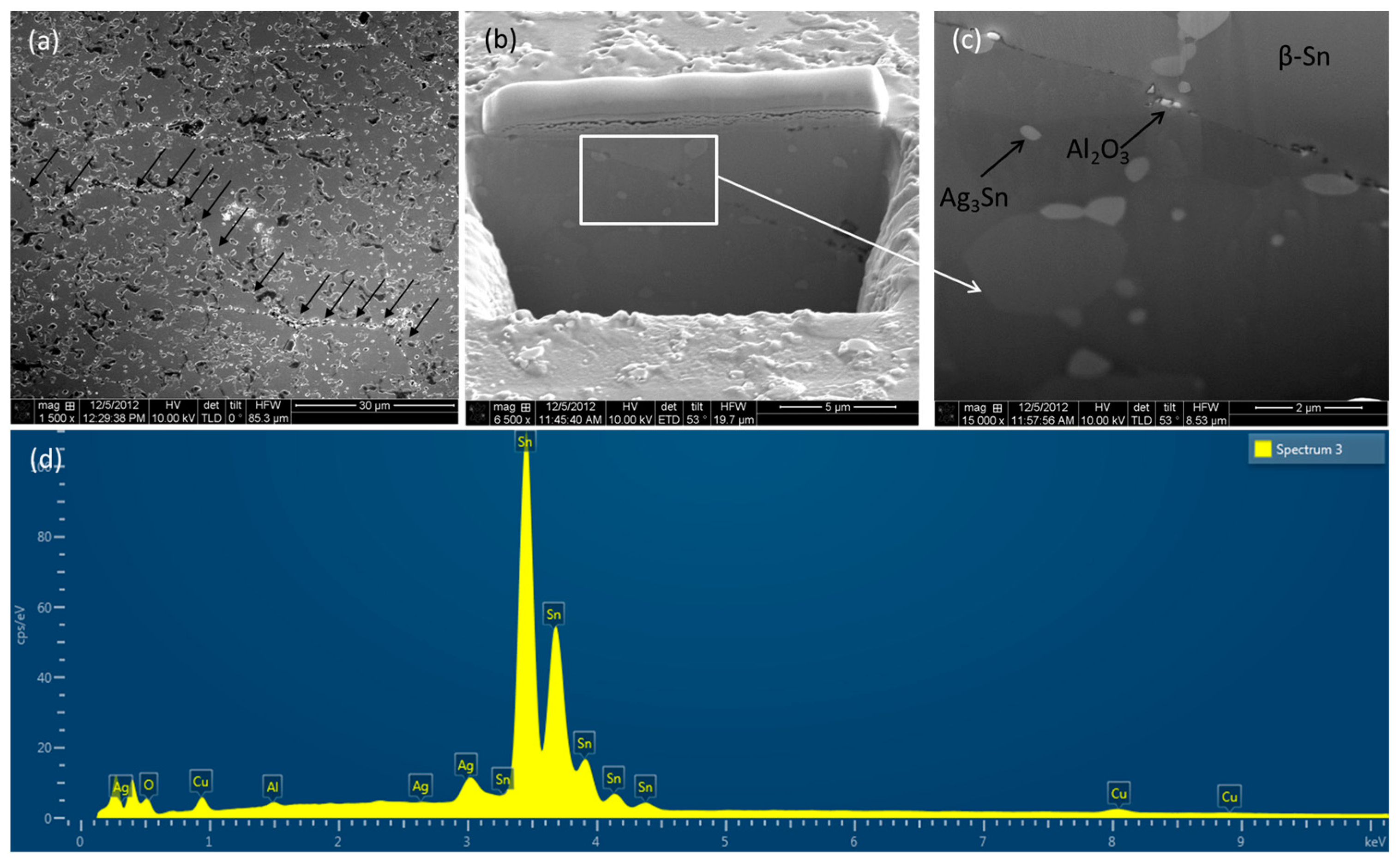
Similar to SAC and SAC1, the matrix is large primary β-Sn grains and IMCs are dispersed in the matrix. Distribution of Al2O3 nanoparticles in the matrix is uniform with a preferential trend to be allocated along β-Sn grain boundaries (Figure 3a). Examination of Cu6Sn5 IMCs by SEM shows that there is no significant change in size and distribution of Cu6Sn5 IMCs between composite and monolithic samples. It suggests that, volume percentage of reinforcement particles is not sufficient to significantly affect the growth dynamics of the Cu6Sn5 in the case of composite samples.
It is a well understood that, fine particles in alloys effectively restrict dislocation movement and thus provide higher yield strength. However, these particles may grow in size due to aging effect, in service and thus loss their impingement properties. In addition to that, when the coherency of the particles within the matrix gradually lost with particle growth, yield strength decreased further [23]. As Al2O3 nanoparticles are hard and thermally stable at relatively high temperature, compared to the IMCs form in the microstructure, it is expected that Al2O3 nanoparticles will restrict such grain growth during ageing/reflowing more effectively than that of FeSn2 and other IMCs. Detailed understanding of such behavior as the strength of the alloys and effect of aging on strength is out of the scope of the present paper and accounted for in our future correspondences.

3.2. Different Phases of Solder Alloys

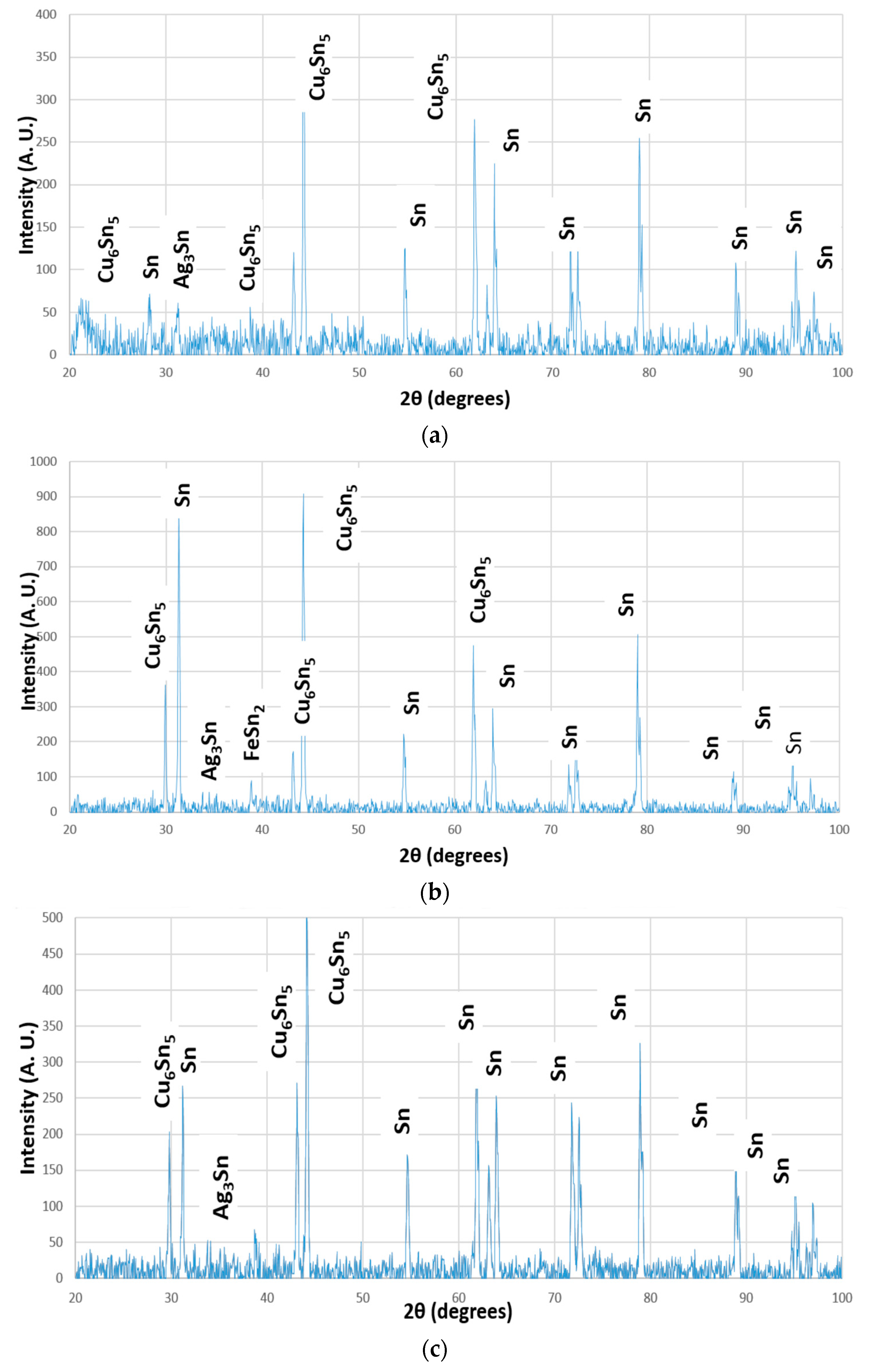
The XRD spectra of SAC and nanocomposite solder alloys are shown in Figure 4. The scattering planes were (111) and (200) for Cu and (101) and (202) for Cu6Sn5. It is evident that, all the alloys including nanocomposites contains Cu6Sn5 and Ag3Sn IMCs predominantly. In addition to that, SAC1 shows the presence of Fe2Sn IMC. Due to high thermal stability, Al2O3 nanoparticles do not contribute towards any phase formation, however, retained as it is, as confirmed by SEM microstructural investigation reported in earlier Section 3.1 [24].

3.3. Thermal Analysis of Solder Alloys

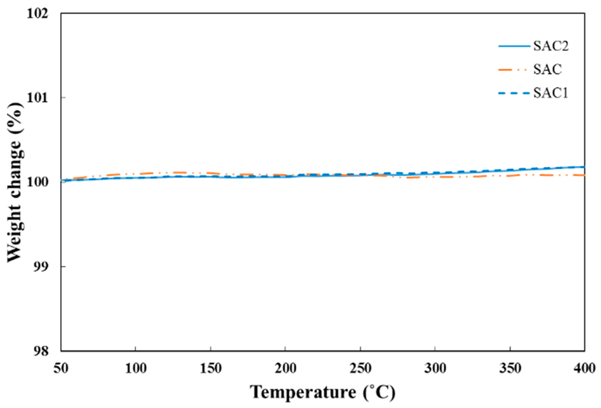
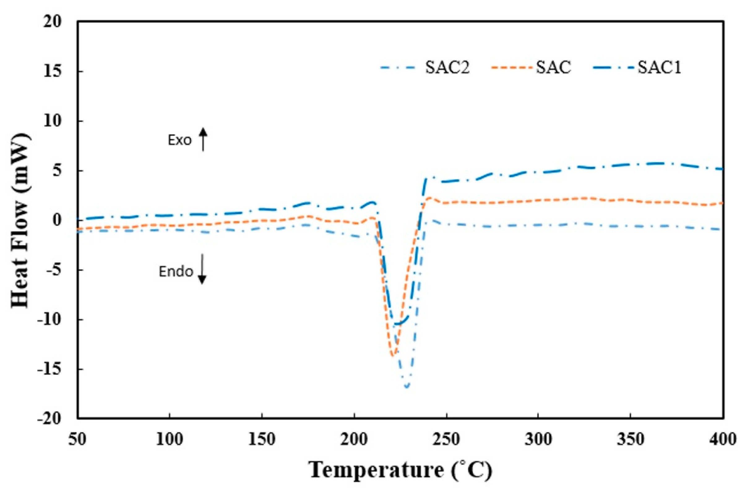
Thermal analysis of the samples was carried out in order to determine the effect of nanoparticles addition in monolithic SAC alloy as shown in Figure 5 and Figure 6. Figure 5 shows thermal gravimetric analysis (TGA) of solder alloys over temperature ranges from 50 °C to 400 °C. As evident, there was not any significantly change over the temperature range which suggest high thermal stability of these material up to 400 °C. Figure 6 shows the differential scanning calorimetry (DSC) of the alloys. Melting temperature of monolithic SAC solder alloy vary with the addition of different nanoparticles (Al2O3, C and Fe) as shown in Figure 6 from DSC analysis. However, this temperature difference took place over a very narrow range, i.e., between 220 °C and 230 °C. This confirms that the addition of nanoparticles in monolithic SAC solder alloy retain the melting temperature in desired range, which is suitable for their intended applications [25,26]. The area under DSC peaks represent energy density of solder alloys and it is 176.02, 175.5 and 178.01 J/g for SAC, SAC1 and SAC2 alloy, respectively. Thus, these materials have the potential to store thermal energy during their phase change from solid to liquid. As shown in Figure 6, melting temperatures are 220.9 °C and 220.8 °C for SAC1 and SAC2 as compared with 221.4 °C for SAC. Thus, with the addition of Fe or Al2O3, melting temperatures only changed slightly with respect to SAC alloy. Fe-bearing solders (SAC1) solidify at relatively lower temperatures than that of SAC during cooling as difficult nucleation of β-Sn can results in high degrees of undercooling prior to solidification. This indicates that β-Sn phase requires a large degree of undercooling to nucleate and solidify, explaining the existence of relatively larger primary β-Sn grains in SAC1 as reported in Section 3.1. The onset transformation temperature for exothermic descent of the curves, which represents the onset of melting, does not change markedly. It is understood that by adding Fe or Al2O3 in SAC, alloy composition has moved away from eutectic values, as shown by the effect of melting point peak broadening from DSC results (Figure 6) [25,26].
The present investigation towards the development Pb-free solder alloys reports the physical and thermal characteristics of mentioned alloys. In this context, investigation on strength and mechanical properties of such alloys are foreseen in our future communications.

4. Conclusions

This current research reports the effect of small amount Fe or Al2O3 nanoparticles addition on microstructure and thermal behaviors of monolithic Pb-free Sn–Ag–Cu alloy. Based on experimental outcomes, the following conclusions can be made:
  • Fe-bearing solder nanocomposite form relatively larger primary β-Sn grains compared to monolithic Sn–Ag–Cu alloy. Fe addition also helps to form FeSn2 IMCs dispersed in matrix and foreseen to restrict grain/ IMCs growth during aging/reflowing.
  • Addition of Al2O3 nanoparticles refine β-Sn grain size, dispersed in the matrix with preferential trend to be accumulated along grain boundaries.
  • Neither Fe nor Al2O3 nanoparticle addition cause any significant effect on thermal behavior compared to Sn–Ag–Cu solder alloys.

Author Contributions

Animesh K. Basak and Alokesh Pramanik conceived and designed the experiments; Hamidreza Riazi and Mahyar Silakhori performed XRD and thermal analysis experiments; Animesh K. Basak, Alokesh Pramanik and Angus K. O. Netting wrote the paper.

Conflicts of Interest

The authors declare no conflict of interest.

References

  1. Miller, C.M.; Anderson, I.E.; Smith, J.F. A Viable Tin-Lead Solder Substitute: Sn-Ag-Cu. J. Electron. Mater. 1994, 23, 595–662. [Google Scholar] [CrossRef]
  2. Anderson, I.E.; Cook, B.A.; Harringa, J.L.; Terpstra, R.L. Sn-Ag-Cu Solders and Solder Joints: Alloy Development, Microstructure, and Properties. JOM 2002, 26–29. [Google Scholar] [CrossRef]
  3. Liu, C.Z.; Chen, J. Nanoindentation of lead-free solders in microelectronic packaging. Mater. Sci. Eng. A 2007, 448, 340–344. [Google Scholar] [CrossRef]
  4. Zou, H.F.; Yang, H.J.; Zhang, Z.F. Coarsening mechanisms, texture evolution and size distribution of Cu6Sn5 between Cu and Sn-based solders. Mater. Chem. Phys. 2011, 131, 190–198. [Google Scholar] [CrossRef]
  5. Deng, X.; Chawla, N.; Chawla, K.K.; Koopman, M. Deformation behaviour of (Cu, Ag)—Sn intermetallics by nanoindentation. Acta Mater. 2004, 52, 4291–4303. [Google Scholar] [CrossRef]
  6. Gao, F.; Takemoto, T. Mechanical properties evolution of Sn-3.5Ag based lead-free solders by nanoindentation. Mater. Lett. 2006, 60, 2315–2318. [Google Scholar] [CrossRef]
  7. Gebhardt, E.; Petzow, G. Ueber den Auf-bau des Systems Silber-Kupfer-Zinn. Zeitschrift fuer Metallkunde 1959, 50, 597–605. [Google Scholar]
  8. Loomans, M.E.; Fine, M.E. Tin-silver-copper eutectic temperature and composition Metall. Mater. Trans. A 2000, 31A, 1155–1162. [Google Scholar] [CrossRef]
  9. Moon, K.W.; Boettinger, W.J.; Kattner, U.R.; Biancaniello, F.S.; Handwerker, C.A. Experimental and thermodynamic assessment of Sn-Ag-Cu solder alloys. J. Electron. Mater. 2000, 29, 1122–1136. [Google Scholar] [CrossRef]
  10. Pramanik, A.; Basak, A.K.; Dong, Y.; Shankar, S.; Littlefair, G. Milling of nanoparticles reinforced Al-based metal matrix composites. J. Compos. Sci. 2018, 2, 13. [Google Scholar] [CrossRef]
  11. Chellvarajoo, S.; Abdullah, M.Z. Microstructure and mechanical properties of Pb-free Sn–3.0Ag–0.5Cu solder pastes added with NiO nanoparticles after reflow soldering process. Mater. Des. 2016, 90, 499–507. [Google Scholar] [CrossRef]
  12. Zhong, X.L.; Gupta, M. Development of lead-free Sn—0.7Cu/Al2O3 nanocomposite solders with superior strength. J. Phys. D Appl. Phys. 2008, 41, 095403. [Google Scholar] [CrossRef]
  13. Salleh, M.A.A.M.; McDonald, S.D.; Nogita, K. Effects of Ni and TiO2 additions in as-reflowed and annealed Sn0.7Cu solders on Cu substrates. J. Mater. Process. Technol. 2017, 242, 235–245. [Google Scholar] [CrossRef]
  14. Niranjani, V.L.; Rao, B.S.S.C.; Sarkar, R.; Kamat, S.V. The influence of addition of nano sized molybdenum and nickel particles on creep behavior of Sn–Ag lead free solder alloy. J. Alloys Comp. 2012, 542, 136–141. [Google Scholar] [CrossRef]
  15. Tao, Q.B.; Benabou, L.; Le, V.N.; Hwang, H.; Lu, D.B. Viscoplastic characterization and post-rupture microanalysis of a novel lead-free solder with small additions of Bi, Sb and Ni. J. Alloys Comp. 2017, 694, 892–904. [Google Scholar] [CrossRef]
  16. Wu, C.M.L.; Yu, D.Q.; Law, C.M.T.; Wang, L. Properties of lead-free solder alloys with rare earth element additions. Mater. Sci. Eng. R 2004, 44, 1–44. [Google Scholar] [CrossRef]
  17. Matin, M.A.; Vellinga, W.P.; Geers, M.G.D. Microstructure evolution in a Pb-free solder alloy during mechanical fatigue. Mater. Sci. Eng. A 2006, 431, 166–174. [Google Scholar] [CrossRef]
  18. Rao, B.S.S.C.; Weng, J.; Shen, L.; Lee, T.K.; Zeng, K.Y. Morphology and mechanical properties of intermetallic compounds in SnAgCu solder joints. Microelectron. Eng. 2010, 87, 2416–2422. [Google Scholar]
  19. Kumar, V.; Fang, Z.Z.; Liang, J.; Dariavach, N. Microstructural Analysis of Lead-Free Solder Alloys. Metall. Mater. Trans. A 2006, 37, 2505–2514. [Google Scholar] [CrossRef]
  20. Deng, X.; Koopman, M.; Chawla, N.; Chawla, K.K. Young’s modulus of (Cu, Ag)–Sn intermetallics measured by nanoindentation. Mater. Sci. Eng. A 2004, 364, 240–243. [Google Scholar] [CrossRef]
  21. Basak, A.K.; Pramanik, A.; Islam, M.N. Failure mechanisms of nanoparticle reinforced metal matrix composite. Adv. Mater. Res. 2013, 774, 548–551. [Google Scholar] [CrossRef]
  22. Shnawah, D.A.A.; Said, S.B.M.; Sabri, M.F.M.; Badruddin, I.A.; Che, F.X. Microstructure, mechanical, and thermal properties of the Sn-1Ag-0.5Cu solder alloy bearing Fe for electronics applications. Mater. Sci. Eng. A 2012, 551, 160–168. [Google Scholar] [CrossRef]
  23. Dieter, G.E. Mechanical Metallurgy, 2nd ed.; McGraw-Hill: Minato-ku, Tokyo, 1976. [Google Scholar]
  24. Basak, A.K.; Eddine, W.Z.; Celis, J.P.; Matteazzi, P. Characterisation and tribological investigation on thermally processed nanostructured Fe-based and Cu-based cermet materials. J. Nanosci. Nanotechnol. 2010, 10, 1179–1184. [Google Scholar] [CrossRef] [PubMed]
  25. Elmer, J.W.; Specht, E.D.; Kumar, M. Microstructure and In Situ Observations of Undercooling for Nucleation of β-Sn Relevant to Lead-Free Solder Alloys. J. Elelctron. Mater. 2010, 39, 273–282. [Google Scholar] [CrossRef]
  26. Reid, M.; Punch, J.; Collins, M.; Ryan, C. Effect of Ag content on the microstructure of Sn-Ag-Cu based solder alloys. Solder. Surf. Mt. Technol. 2008, 20, 3–8. [Google Scholar] [CrossRef]
Figure 1. Sn–Ag–Cu solder alloy: (a) top-view SEM micrograph; (b) cross-section view SEM micrograph; (c) zoom-in view of the area marked in (b) and (d) energy dispersive X-ray (EDX) spectra at (a) with quantitative analysis as an insert.
Jcs 02 00028 g001
Figure 2. Sn–Ag–Cu solder alloy reinforced with Fe nano-particles (SAC1): (a) top-view SEM micrograph; (b) cross-section view SEM micrograph; (c) zoom-in view of the area marked in (b) and (d) EDX spectra at (a).
Jcs 02 00028 g002
Figure 3. Sn–Ag–Cu solder alloy reinforced with Al2O3 nano-particles (SAC2): (a) top-view SEM micrograph; (b) cross-section view SEM micrograph; (c) zoom-in view of the area marked in (b) and (d) EDX spectra at (a).
Jcs 02 00028 g003
Figure 4. XRD spectra of solder alloys: (a) Sn–Ag–Cu alloy; (b) Sn–Ag–Cu alloy reinforced with Fe nanoparticles and (c) Sn–Ag–Cu alloy reinforced with Al2O3 nano-particles.
Jcs 02 00028 g004
Figure 5. TGA analysis of solder alloys.
Jcs 02 00028 g005
Figure 6. Differential scanning calorimetry (DSC) analysis of solder alloys.
Jcs 02 00028 g006