Fabrication of Fiber Reinforced Plastics by Ultrasonic Welding


Abstract
:1. Introduction
2. Materials and Methods
2.1. Machines
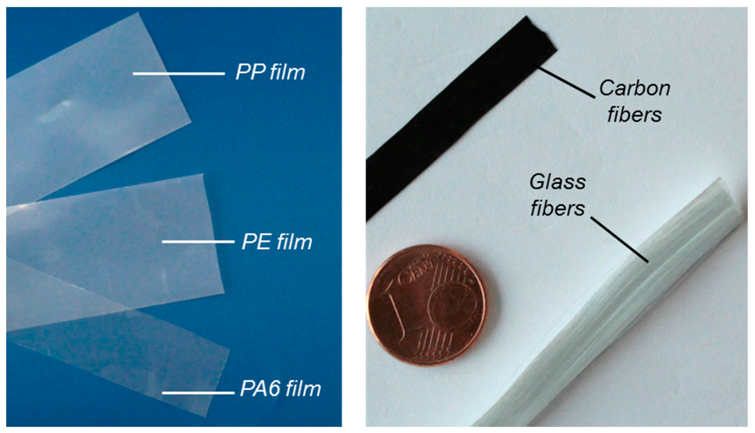
2.2. Materials
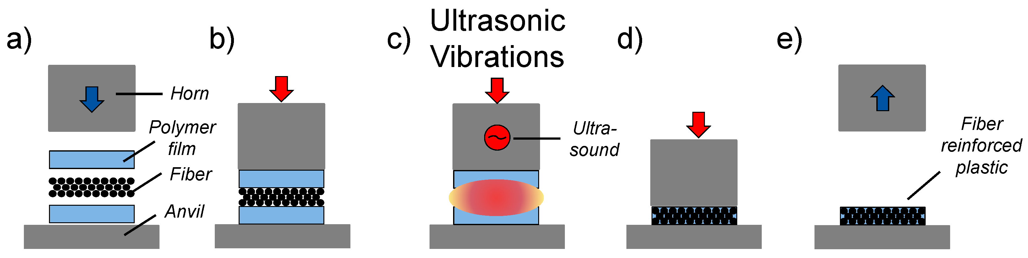
2.3. Methods
3. Results
3.1. Ultrasonic Fabrication of Multi Layered CFRP
3.2. Ultrasonic Fabrication of GFRP
3.3. Ultrasonic Fabrication of CFRP-Plates
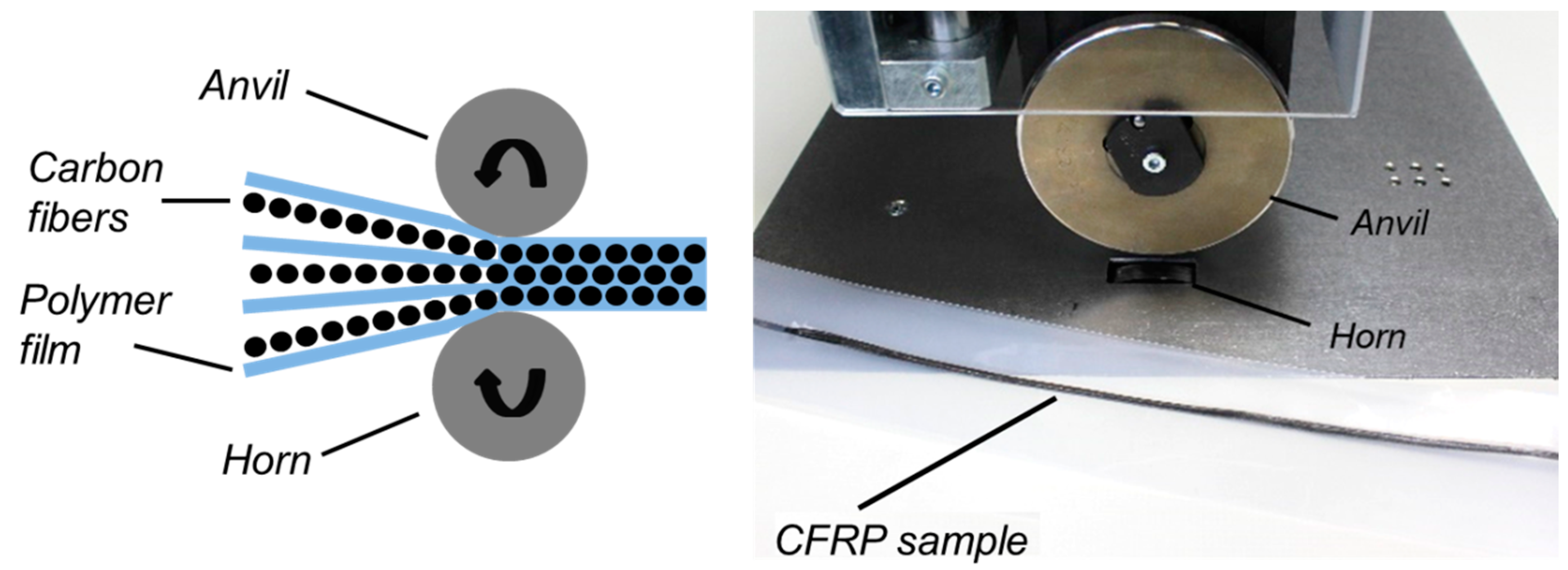
3.4. Continuous Ultrasonic Fabrication of CFRP
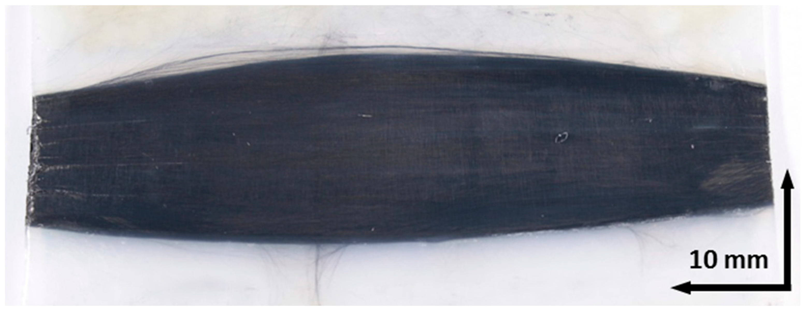
3.5. Mechanical Testing
4. Discussion
5. Conclusions
Author Contributions
Funding
Conflicts of Interest
References
- Neitzel, M.; Mitschang, P.; Breuer, U. Handbuch Verbundwerkstoffe—Werkstoffe, Verarbeitung, Anwendung, 2nd ed.; Carl Hanser: Munich, Germany, 2014; ISBN 978-3-446-43696-1. [Google Scholar]
- Lengsfeld, H.; Wolff-Fabris, F.; Krämer, J.; Lacalle, J.; Altstädt, V. Faserverbundwerkstoffe—Prepregs und ihre Verarbeitung, 1st ed.; Carl Hanser: Munich, Germany, 2014; ISBN 978-3-446-43300-7. [Google Scholar]
- Kraus, T.; Kühnel, M.; Witten, E. Composites-Marktbericht 2016—Markt-entwicklungen, Trends, Ausblicke und Herausforderungen, 1st ed.; Carbon Composites e.V.: Augsburg, Germany, 2016. [Google Scholar]
- Suzuki, T.; Takahashi, J. Prediction of Energy Intensity of Carbon Fibre Rein-forced Plastics for Mass-Produces Passenger Cars. In Proceedings of the 9th Japan Interna-Tional SAMPE Symposium, Tokyo, Japan, 25–28 April 2005. [Google Scholar]
- Sackmann, J.; Burlage, K.; Gerhardy, C.; Memering, B.; Liao, S.; Schomburg, W.K. Review on ultrasonic fabrication of polymer micro devices. Ultrasonics 2015, 56, 189–200. [Google Scholar] [CrossRef] [PubMed]
- Daniels, H.P.C. Ultrasonic Welding. Ultrasonics 1965, 3, 190–196. [Google Scholar] [CrossRef]
- Palardy, G.; Villegas, I.R. On the effect of flat energy directors thickness on heat generation during ultrasonic welding of thermoplastic composites. Compos. Interfaces 2017, 24, 203–214. [Google Scholar] [CrossRef]
- Villegas, I.R.; Moser, L.; Yousefpour, A.; Mitschang, P.; Bersee, H.E. Process and performance evaluation of ultrasonic, induction and resistance welding of advanced thermoplastic composites. J. Ther. Compos. Mater. 2012, 26, 1007–1024. [Google Scholar] [CrossRef]
- Jongbloed, B.; Teuwen, J.; Palardy, G.; Villegas, I.F. Improving weld uniformity in continuous ultrasonic welding of thermoplastic composites. In Proceedings of the 18th European Conference on Composite Materials (ECCM18), Athens, Greece, 25–28 June 2018. [Google Scholar]
- Gomer, A.; Sackmann, J.; Schomburg, W.K. Gefügige Kunststoffe. Kunststoffe 2016, 12, 73–75. [Google Scholar]
- Tsiangou, E.; Teixeira de Freitas, S.; Villegas, I.F.; Benedictus, R. Ultrasonic welding of CF/Epoxy to CF/PEEK composites: Effect of the energy director material on the welding process. In Proceedings of the 18th European Conference on Composite Materials (ECCM18), Athens, Greece, 25–28 June 2018. [Google Scholar]
- Voleppa, Q.; Pardoenb, T.; Baillya, C. Thermoset composite assembling method by welding of thermoplastic surface layers: Microstructure and toughness of the resulting thermoplastic/epoxiy resin interfaces. In Proceedings of the 16th European Conference on Composite Materials (ECCM16), Sevilla, Spain, 22–26 June 2016. [Google Scholar]
- Rizzolo, R.H.; Walczyk, D.F. Ultrasonic consolidation of thermoplastic composite prepreg for automated fiber placement. J. Ther. Compos. Mater. 2016, 29, 1480–1497. [Google Scholar] [CrossRef]
- Dell’Anna, R.; Lionetto, F.; Montagna, F.; Maffezzoli, A. Lay-Up and Consolidation of a Composite Pipe by In Situ UltrasonicWelding of a Thermoplastic Matrix Composite Tape. Materials 2018, 11, 786. [Google Scholar] [CrossRef] [PubMed]
- Pasternak, M. Laminieren von Carbon-Preforms. Kunststoffe 2012, 10, 188–189. [Google Scholar]
- Pasternak, M. Ultraschall als Energiequelle zum Laminieren von CFK—Schallwellen richten Carbonfasern aus. Plastverarbeiter. Available online: https://www.plastverarbeiter.de/38200/schallwellen-richten-carbonfasern-aus/ (accessed on 14 September 2018).
- Khaled, Y.; Mehdi, H. Processing of thermoplastic matrix composites through automated fiber placement and tape laying methods. J. Ther. Compos. Mater. 2017, 1, 1–150. [Google Scholar] [CrossRef]
- Chu, Q.; Li, Y.; Xiao, J.; Huan, D.; Zhang, X.; Chen, X. Processing and characterization of the thermoplastic composites manufactured by ultrasonic vibration-assisted automated fiber placement. J. Ther. Compos. Mater. 2018, 11, 339–358. [Google Scholar] [CrossRef]
- Lionetto, F.; Dell’Anna, R.; Montagna, F.; Maffezzoli, A. Ultrasonic assisted consolidation of commingled thermoplastic/glass fibre rovings. Front. Mater. 2015, 2, 1–9. [Google Scholar] [CrossRef]
- Lionetto, F.; Dell’Anna, R.; Montagna, F.; Maffezzoli, A. Modeling of continuous ultrasonic impregnation and consolidation of thermoplastic matrix composites. Compos. Part A Appl. Sci. Manuf. 2016, 82, 119–129. [Google Scholar] [CrossRef]
- Technical Data Sheet Branson 2000IW+ Ultrasonic Welder. Available online: http://www.emerson.com/en-us/catalog/branson-2000iw-ultrasonic-welder (accessed on 20 July 2018).
- Technical Data Sheet HiQ DIALOG SpeedControl Ultrasonic Welding Machines. Available online: https://www.herrmannultraschall.com/en/products/ultrasonic-welding-machines/weld-machines-hiq-production-series/ (accessed on 20 July 2018).
- Technical Data Sheet CERA 100 Ultrasonic Welding Machines. Available online: www.cera-groupecera.com/en/standards/machines-to-weld-and-or-cut-by-sonics/cera-ultrasonic-ultrasonic-sewing (accessed on 20 July 2018).
- Technical Data Sheet Zwicki Line Materials Testing Machines Z5.0 Tensile Testing Machine. Available online: https://www.zwick.co.uk/universal-testing-machines/zwickiline (accessed on 20 July 2018).
- Tecfilm PP TC 00170 Data Sheet; Dr. Dietrich Müller GmbH: Ahlhorn, Germany; Available online: www.mueller-ahlhorn.com/fileadmin/Downloads/PDF/PDFDateien/TC_00170_de.pdf (accessed on 14 September 2018).
- Nowocast HD Data Sheet; Nowofol Kunststoffprodukte GmbH & Co. KG: Siegsdorf, Germany, 2018.
- Cast Nylon Film PA 6 Data Sheet; Mf-Folien GmbH: Kempten, Germany, 2018.
- Technical Data Sheet Tenax—HTS40 F13 12K 800tex Carbon Fiber Roving. Available online: https://www.teijincarbon.com/de/produkte/tenax%c2%ae-kohlenstofffaser/tenax%c2%ae-filamentgarn/ (accessed on 20 July 2018).
- E-CR1200 Data Sheet; Mühlmeier GmbH & Co. KG: Bärnau, Gemany. Available online: https://www.muehlmeier.de/fileadmin/user_upload/DE/composite/produktinformation/muehlmeier_de_rovings_e-cr-glas_direktroving.pdf (accessed on 14 September 2018).
- Technical Data Sheet KDL-8003 Carbon Fiber Canvas. Available online: https://www.carbon-vertrieb.com/shop/product_info.php?products_id=1319&MODsid=jgjvpnod8p4jbnrjb34arkajtq1brhm2 (accessed on 20 July 2018).
- Technical Data Sheet Celstran CFR-TP PPS CF-60-01_-PPS Carbon Fiber Tape. Available online: http://tools.celanese.com/standard/main/quicksearch/ds/0 (accessed on 20 July 2018).


| Process | Welding Force (N) | Trigger Force (N) | Welding Time (s) | Holding Time (s) | Ultrasonic Amplitude (µm) |
|---|---|---|---|---|---|
| A: 1 layer of carbon fibers, 100 µm in thickness, and 2 layers of PP foils, each 200 µm. | 3200 | 220 | 1.5 | 1.0 | 32.0 |
| L: 3 layers of carbon fibers, each 100 µm in thickness, and 4 layers of PA foils, each 200 µm. | 1800 | 870 | 1.5 | 1.0 | 30.4 |
| Process | Welding Force (N) | Trigger Force (N) | Welding Time (s) | Holding Time (s) | Ultrasonic Amplitude (µm) |
|---|---|---|---|---|---|
| B: 6 layers of carbon fibers, each 100 µm in thickness, and 7 layers of PP foils, each 200 µm. | 500 | 600 | 0.65 | 2.0 | 30.0 |
| Process | Welding Force (N) | Trigger Force (N) | Welding Time (s) | Holding Time (s) | Ultrasonic Amplitude (µm) |
|---|---|---|---|---|---|
| C: 8 layers of carbon fibers, each 100 µm in thickness, and 9 layers of PA foils, each 100 µm. | 500/2000 | 500 | 3.0 | 5.0 | 22.0 |
| D: 17 layers of carbon fibers, each 100 µm in thickness, and 18 layers of PA foils, each 100 µm. | 1200/2000 | 1200 | 15.0 | 5.0 | 30.0 |
| E: 4 layers of carbon fibers, each 100 µm in thickness, and 5 layers of PA foils, each 100 µm. | 500/2000 | 500 | 4.0 | 5.0 | 30.0 |
| F: 5 layers of CFRP made within process E | 500/2000 | 500 | 6.0 | 5.0 | 20.0 |
| G: 4 layers of glass fibers, each 200 µm in thickness, and 5 layers of PA foils, each 100 µm. | 2000 | 500 | 4.5 | 5.0 | 30.0 |
| H: 3 layers of canvas, each 300 µm in thickness, and 8 layers of PA foils, each 100 µm. | 500/2000 | 500 | 16.0 | 5.0 | 30.6 |
| M: 5 layers of carbon fibers, each 100 µm in thickness, and 6 layers of PA foils, each 100 µm. | 500/2000 | 500 | 4.5 | 5.0 | 30.0 |
| N: 8 layers of carbon fibers, each 100 µm in thickness, and 9 layers of PA foils, each 100 µm. | 500/2000 | 500 | 7.0 | 5.0 | 30.0 |
| Process | Piston Pressure (MPa) | Feed (m/min) | Ultrasonic Amplitude (µm) |
|---|---|---|---|
| I: 3 layers of carbon fibers, each 50 µm in thickness, and 4 layers of PE foils, each 150 µm in thickness. | 0.5 | 4.0 | 20 |
| J: 2 layers of carbon fibers, each 50 µm in thickness, and 3 layers of PA foils, each 100 µm in thickness. | 0.4 | 4.0 | 17.5 |
| K: 1 layer of carbon fibers, 50 µm in thickness, and 2 layers of PP foils, each 200 µm in thickness. | 0.3 | 4.0 | 20 |
| Process | Mean Tensile Strength (MPa) | Standard Deviation (%) | Samples Tested (-) |
|---|---|---|---|
| L: 3 layers of carbon fibers, each 100 µm in thickness, and 4 layers of PA foils, each 200 µm. | 502 ± 42 | 8.4 | 5 |
| E: 4 layers of carbon fibers, each 100 µm in thickness, and 5 layers of PA foils, each 100 µm. | 819 ± 113 | 13.8 | 17 |
| M: 5 layers of carbon fibers, each 100 µm in thickness, and 6 layers of PA foils, each 100 µm. | 1001 ± 142 | 14.2 | 14 |
| N: 8 layers of carbon fibers, each 100 µm in thickness, and 9 layers of PA foils, each 100 µm. | 1240 ± 130 | 10.5 | 14 |
© 2018 by the authors. Licensee MDPI, Basel, Switzerland. This article is an open access article distributed under the terms and conditions of the Creative Commons Attribution (CC BY) license (http://creativecommons.org/licenses/by/4.0/).
Share and Cite
Gomer, A.; Zou, W.; Grigat, N.; Sackmann, J.; Schomburg, W.K. Fabrication of Fiber Reinforced Plastics by Ultrasonic Welding. J. Compos. Sci. 2018, 2, 56. https://doi.org/10.3390/jcs2030056
Gomer A, Zou W, Grigat N, Sackmann J, Schomburg WK. Fabrication of Fiber Reinforced Plastics by Ultrasonic Welding. Journal of Composites Science. 2018; 2(3):56. https://doi.org/10.3390/jcs2030056
Chicago/Turabian StyleGomer, Andreas, Wei Zou, Niels Grigat, Johannes Sackmann, and Werner Karl Schomburg. 2018. "Fabrication of Fiber Reinforced Plastics by Ultrasonic Welding" Journal of Composites Science 2, no. 3: 56. https://doi.org/10.3390/jcs2030056
APA StyleGomer, A., Zou, W., Grigat, N., Sackmann, J., & Schomburg, W. K. (2018). Fabrication of Fiber Reinforced Plastics by Ultrasonic Welding. Journal of Composites Science, 2(3), 56. https://doi.org/10.3390/jcs2030056