Article

Numerical Simulations of Azobé/Urea Formaldehyde Wood Plastic Composite Behaviors under Charpy Impact and Low-Velocity Drop Weight Tests

1
Laboratory of Analyses Simulations and Testing, Institute of Technology, The University of Ngaoundéré, P.O. Box 455 Ngaoundéré, Cameroon
2
Laboratoire de Mécanique et Productique (LMP), UFD SI, Université de Douala, P.O. Box 24157 Douala, Cameroon
3
Laboratory of Mechanics, Materials and Photonics, Faculty of Sciences, The University of Ngaoundéré, P.O. Box 455 Ngaoundéré, Cameroon
*
Author to whom correspondence should be addressed.
J. Compos. Sci. 2018, 2(4), 60; https://doi.org/10.3390/jcs2040060
Submission received: 14 August 2018 / Revised: 2 October 2018 / Accepted: 13 October 2018 / Published: 17 October 2018

Abstract

:
This work is concerned with the study of the influence of impactor’s velocity parameters, impactor’s geometry, the target plate properties, and thickness, on the response of a tropical wood plastic composite (WPC) Azobé/urea formaldehyde (Az/UF) plate under impact loading. Variations of the impact force, displacement, deformation, and impact energy of the specimens with weight fractions of 10, 20, 30, 40, and 50% have been considered in finite element analysis (FEA) simulations. The simulations of the Charpy and of a drop weight impact test on the WPC were carried out using the explicit dynamics module of ANSYS Workbench, which handles problems of dynamic loading of a short duration for 2D and 3D analyses. Contact laws that account for the compressibility of the interacting bodies (the standard steel impactor and the WPC target plate), have been used. The results show that the displacements decrease in contrast to the increase of the wood filler content, and vary in the 6.8–9.0 mm interval. From an energetic point of view, it is observed that the maximum absorbed energy is between 40 and 50% for the Azobe flour wt.%, with energy absorption rates of 28% and 26% of the total energy. These results are in agreement with those reported in previous experimental investigations on hybrid WPCs filled with wood flour and glass fibers, which produce an energy absorption rate of 24–26%. These results promote the applicability of Azobé tropical wood in fabricating WPCs for impact loading situations.

1. Introduction

The replacement of organic fibers with plant fillers (PFs) in composite materials presents several advantages, particularly in the field of transportation [1,2]. However, most of the commonly used composites are highly sensitive to impact loading, which can cause internal defects, not visually detectable, and a significant loss of the materials’ mechanical properties [1,3,4,5]. While the static flexural, toughness, and tensile properties of wood plastic composite (WPC) have been addressed in numerous research investigations [2,6,7], their response under impact loading is yet to be elucidated. The evaluation of this response would be important in predicting the strength of the WPC structures as well as the dynamic load limits that a structure can withstand.
The impact properties of wood/polypropylene (wood/PP) composites have been reported in the literature [8,9,10,11,12,13]. Accordingly, the influence of the chemical modification and coupling agents such as maleic anhydride-grafted polypropylene (MAPP), ethylene vinyl acetate (EVA), and ethylene propylene/diene monomer elastomer (EPDM) was assessed. An improvement in the impact resistance of the studied composites was reported. It was shown that the impact resistance of the materials decreases with the increasing stiffness. The impact resistance of WPCs also decreases as the wood content increases, after an optimal value and higher strain rates had been obtained with the composites with highest impact resistance [8,14,15]. The high modulus wood fiber stiffens the polyethylene matrix and gradually changes the composite behavior from ductile to brittle with the increase of the fiber content. As the fiber content increases, the matrix becomes more fragile and the ability of the material to absorb the impact energy decreases, regardless of the type of fibers used. Moreover, an increase in the fiber content involves more fiber–fiber interactions. These interactions have a detrimental effect on most of the mechanical properties if there are fiber agglomerations that cause a stress concentration and that decrease the tensile strength and impact resistance. On the contrary, a strong polymer–fiber interaction increases the tensile and impact resistance, as it enables a better stress transfer. In addition, the matrix coating is another concern. Large particles are easier to coat with molten polymers than small particles. Small particles are more prone to agglomerate; this increases the amount of non-coated agglomerated filler particles in the composite [11].
The impact resistance greatly decreases with the increase, beyond an optimal value, of the filler volume fraction. Likewise, a 20% increase in the wood content causes a gradual decrease of the toughness up to 9 kJ·m−2, whereas for the 0% material, the toughness is 51 kJ·m−2. This is because the linear medium density polyethylene (LMDPE) that forms the matrix is an extremely tough material, whereas this is not the case with wood that is rather rigid. In addition, as mentioned above, wood–wood interactions increase with the wood powder content [11]. So, there are more particles agglomerating and acting as stress concentrator, which weakens the material. Dobreva et al. [11] studied the effect of the coupling agent, monochloroacetic acid, on the properties of wood/PP. A good impact resistance evolving from 2.6 to 4.8 kJ·m−2 was reported. However, they recommended using a fair content of this coupling agent, as an excessive dosage would seriously impair the interfacial interactions between the PP matrix and wood flour (e.g., the formation of a plastic zone around the wood particles and the ductility reduction of the polypropylene matrix). Impact resistance is one of the most interesting properties of WPC, particularly of wood/PP, when it is used for structural applications. As also reported by Cerbu et al. [16], the Charpy impact test (CIT) resistance decreases with the increase of the reinforcement content.
Teng and Wierzbicki carried out Charpy impact tests on PP based WPCs [17] test specimens consistent with ASTM D 6110-97 [18]. Their tests were used to monitor the variation of the toughness as a function of the pendulum heights or angular positions. There is a clear drop in the rupture energy for increasing the initial angular positions. A study by Stan [19] focused on the effect of glass fibers on the impact properties of wood flour-based WPCs. In fact, the tests were carried out to evaluate the influence of the initial velocity values, namely, 2, 4, and 5 m·s−1 on the drop weight peak force, peak displacement, and impact energy. The tests were performed according to the ASTM-D 5420-98a protocol for a drop weight test. Cerbu et al. [16], on the other hand, carried out other Charpy impact tests on hybrid WPCs (containing glass fibers). The study accounted for the structural parameters of composites, such as the number of plies and the type of reinforcement so as to evaluate the toughness.
Four broad categories of impact that correspond to very distinct applications and contexts can be defined, low-velocity, intermediate or moderate velocities, high velocity, and ballistic impacts. A low-velocity impact is considered when the impactor’s velocity is less than 10 m·s−1 and its mass is between 50 g and 30 kg, depending on the application [1,20,21]. The damage mechanisms that generally occur are compression and local bending [22]. The low-velocity category is also valid when the propagation of the waves in the thickness do not influence the structural integrity. Specifically, when the impactor hits the target, compression and shear occur, and the Rayleigh (surface wave) waves are propagated. After several round-trips through the thickness, the motion of the structure is initiated [23]. The impacts after which damage is introduced after the motion of the structure are categorized as low-velocity impacts [24]. Some authors clearly identify the area of the intermediate or moderate velocities [25,26]. It can be noted that for moderate-velocity impacts, damage, such as in the case of thin structures, is an intermediate mode between bending and local damage in a transversal shear [23]. The high-velocity impact is studied in the framework of satellite protections or launchers against very low-mass space debris (some milligrams), but can reach speeds of several kilometers per second. Ballistic impacts can be considered as a sub-area of high-velocity impacts and are studied in the context of military applications, and are subject to specific standards [27].
The geometry of the impactor, particularly the shape of the impacting tip, has a significant influence on the fracture mode and the ballistic limit of the targeted plate. Wilkins [28] presented some types of target (thin plates) ruptures that depend on the shape of the impactor’s tip. The most usual studied impactors in the literature have a cylindrical shape and differ from the geometry of the impacting tip, of which the most well-known are the hemispherical, conical, flat, and sometimes a combination of all of these geometries. The most used materials are often metals, including many that are iron-based, ranging from mild steel to the most complex forms of alloy steel, with hardness of up to 64 HRC (σUT ≃ 2500 MPa). Other types of materials are also used for ballistic purposes, such as aluminum (pure or in alloy form), magnesium, copper, brass, titanium, tantalum, tungsten, tungsten carbide, and even depleted uranium, as well as a wide variety of plastics and ceramics, such as polyethylene and glass [29].
Another impactor parameter that was studied by the researchers is the aspect ratio of l/d (where d is the diameter and l the length of the impactor). It is reported to have a significant influence on the penetration capacity of the impactor. In general, the effect of the aspect ratio is examined for a wide range of impact velocities. Studies on the aspect ratio in the range of 1–10 are most found in the literature; aspect ratios that are greater than 10 are subjected to bending during perforation. Other works have shown that the aspect ratio has a significant influence on the perforation process of thick plates, and that this effect vanishes at a high-impact velocity [30,31,32]. However, the influence of a high aspect ratio value has not been investigated. Nevertheless, for thin plate perforation tests (thickness of the plate strictly below the projectile diameter), the important parameters of the impactor are its mass and the geometry of the impacting tip.
Damage mechanisms under impact loading are also of interest, from the material structure design viewpoint. Steel parts absorb impact energy through plastic deformation, while composite materials absorb it through damage mechanisms [32]. The interest of composites here is their ability to absorb energy through inelastic damage and deformation [32]. According to Sutherland et al. and Hirai et al. [33,34], impact damage occurs in the following two stages: internal damage to the material at a low energy, and then finally, the perforation of the plate. The damage mechanisms may vary with changes in the many material parameters, such as fiber/resin type, ratio, architecture and interface, and the laminate fabrication method [24,35]. Therefore, theories to describe the overall response, such as energy balance and mass spring methods, are more realistic. Moreover, as these damage mechanisms also strongly depend on the exact nature of the impact event [36,37], the response to the impact of a composite material is very difficult to standardize.
In general, the damage mechanisms in the composite consist of micro-cracking of the matrix, fiber curvature, fiber–matrix interface de-cohesion, and fiber failure. The first three processes often cause a gradual degradation of the material, resulting in a dissipation of high energy, while the last mechanism precedes the collapse of the material [38]. Cracks in the matrix and the breakage of fibers are produced during the impact tests, where the material offers the least resistance, while the impactor makes its way into the thickness of the plate [39]. According to Espinosa et al. [40], the fiber fracture is mainly located on the external face of the impacted plate. These fiber breakages are located in the imprint area and have a material/impactor contact, but on the opposite side of the plate, the fiber breakages result from the traction forces. This type of damage is low in the impacted plate.
The evaluation of the energy dissipation during impact is crucial in characterizing the material impact behavior. For low-velocity impacts, the potential energy provided by the impactor is converted into a damage creation energy (rupture, debris, etc.), an elastic deformation energy of the impacted structure, and an energy dissipated by vibration damping [39]. During an impact, the energy corresponding to the rebound height of the impactor is directly related to the energy causing the damage [34].
For high-velocity impacts (velocity greater than 100 m·s−1), the impact duration is extremely short, and the elastic deformation energy becomes low. A great part of the initial energy is thus transferred to the creation of damage in the plate. The duration of the impact decreases, depending on the increase in the stiffness of the impacted structure. The impact time increases when the damage appears (decrease of the local stiffness of the impacted plate). For the analysis of low-velocity impact damage, many analytical and numerical models were developed by various authors. Anderson [41] published an extensive review of the analytical penetration models developed to describe the mechanics of penetration into metallic targets. The applicability of these models to wood, polymers, or WPCs requires further investigation.
While most of the research work on WPCs is concerned with the analysis of the static flexural, traction, and Charpy impact properties, their response under dynamic impact is yet to be elucidated. The knowledge of this response would be of major use in predicting its impact resistance under various dynamic loads that are to be exerted on. As mentioned above, previous investigations have reported that the mechanical properties of the WPCs are closely related to the content of the filler material, a variable that significantly influences the density and therefore the response to impact stresses. To the best of our knowledge, to date, the finite element analysis (FEA) work on WPC impact behavior has been limited to specialized problems, and no work has been done on low-velocity drop weight or Charpy tests of Azobé/UF WPC. A good agreement between the experimental and FE results is to be achieved when comparing the dynamic force, strain histories, and damage patterns between the experimental measurements and finite element simulations.
Therefore, in this work, we purpose to numerically analyze the mechanical behavior Azobé/UF WPCs, as function of their material structural parameters. The results will help to better evaluate the impact performance and to understand the damage mechanisms of these materials. Hence, our study focuses on the following objectives: numerically assessing the response under low-velocity impactors, predicting the WPC behavior in non-perforating impact load situation, and numerically evaluating the energy required for the rupture of the WPC Azobé/UF.

2. Materials and Methods

2.1. Materials

Azobé/UF WPCs plates of 300 × 120 × 7 mm3 and varying Azobé flours wt.% were used herein for testing. Table 1 summarizes their relevant mechanical properties, as obtained from the literature [42]. The longitudinal and transverse moduli for direction i, Ei, and Gi are in MPa. The number and the A in the specimen label stand for the wood flour wt.% and Azobé wood, respectively. ν i represents the Poisson’s ratios.

2.2. Methods

The consideration of various WPCs’ real service conditions, like dropped tools, bird strikes, and runaway debris, has led to the choice of impactors’ geometry, particularly the shape of the impacting tip, which has a significant influence on the fracture. Two standard tests were carried out in this work, the drop weight and Charpy impact tests.

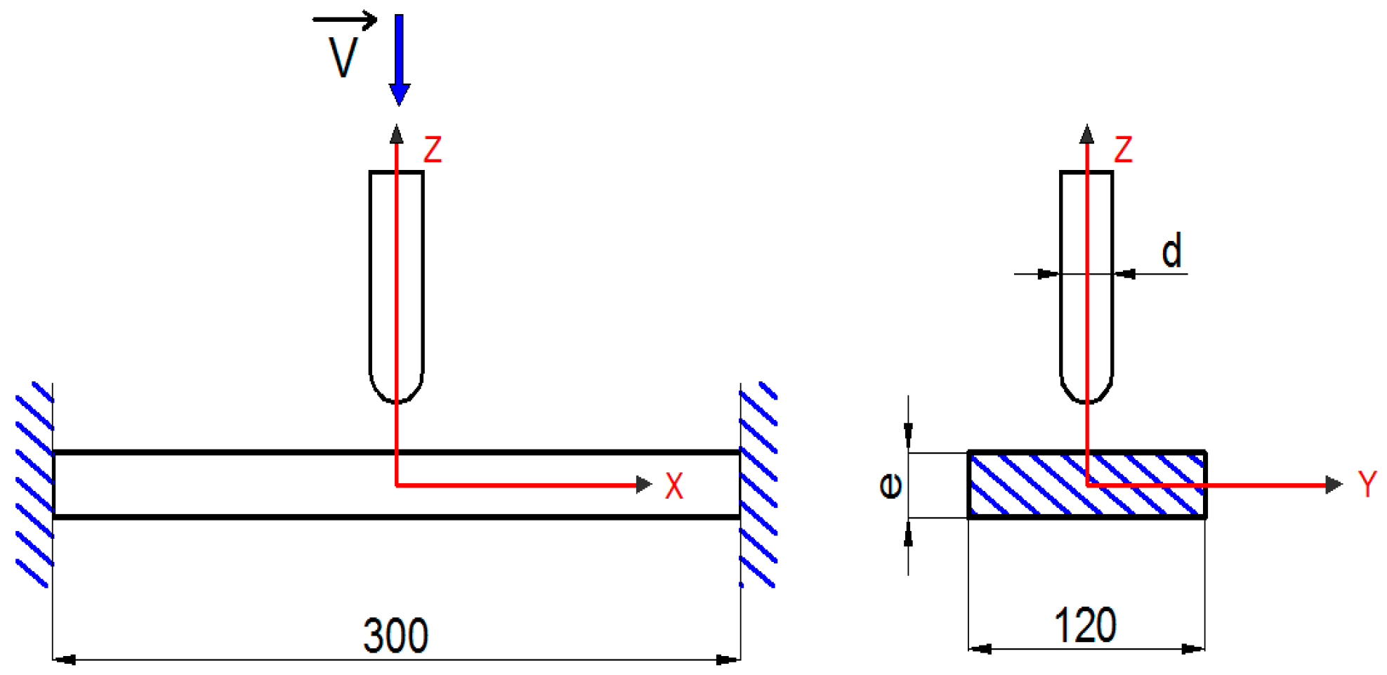
2.2.1. Drop Weight Test

The drop weight test (DWT) specimen, shown in Figure 1 (dimensions unit is mm) and in Figure 2 (FEA 3D model), is a WPC plate and is 7 mm thick, on which a steel projectile is projected at its center. The composite plate has built-in ends and the projectile is launched at speeds less than or equal to 10 m·s−1; namely 5 m·s−1, 8 m·s−1, and 10 m·s−1.
To evaluate the occurring damage mechanisms, three impactors of different impacting tip shapes (Figure 3, with dimensions in mm), including hemispherical, conical, and ogive, were used.
The impactors’ material properties are as follows: density of 7850 kg·m−3, tensile and compressive modulus of elasticity of 2 × 10¹¹ Pa and 1.67 × 10¹¹ Pa, respectively. Poisson’s ratio is 0.3 and Heat Capacity of 434 J·kg−1·°C−1.

2.2.2. Charpy Impact Test

Figure 4 shows a 3D model of the standard Charpy V-notch (CVN) impact specimens, with a V-notch of 2 mm in depth, used for the impact test simulations.

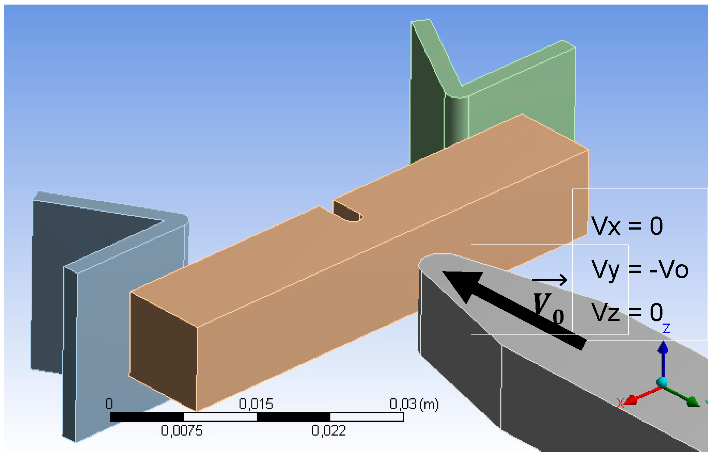
2.2.3. ANSYS Simulation Procedures

The simulations were carried out within the Explicit Dynamics module in ANSYS Workbench, which handles problems of dynamic loading with short durations, for 2D and 3D analyses. Contact laws, which account for the compressibility of the interacting bodies (the standard steel projectile and the WPC target plate), were used. The Lagrangian three-dimensional AUTODYN-3D calculation code was used for the simulations, as it is designed for dynamic response in large deformations of nonlinear solid contacts, explosions, shocks, blows, and penetration. The explicit version of AUTODYN-3D that uses an explicit integration scheme over time was the main algorithm. This scheme corresponds to the centered finite difference method and leads to a system of linear equations, of which resolution is direct, requiring no iterative process. The kinematic friction coefficient between the plate and impactor was kept constant at 0.1.
The impactor and the targeted WPC plate were 3D-discretized. The field equations of the physics of continuous media were evaluated by finite difference techniques. In order to take into account the compressibility of the interacting materials, contact laws were used to model the interaction between the impactor and the targeted WPC plate. The CVN was used to determine the fracture resistance of the materials under the effect of a shock through the rupture energy. Finally, the representation of the drop weight situations on a section of this composite made it possible to study the deformations and stresses, and to consider its damage mechanism further. The simulations were carried out for low-velocity impacts.
The material and kinematic properties of each element of the mesh were chosen in such a way that the mass, the amount of motion, and the internal energy be kept constant, and that the constitutive equations can be fulfilled. This would allow for evaluating the WPC damage through the resulting strains and stresses, impact force, displacement, and energy.
The stability condition of this method is associated with the time increment that must be less than a certain critical value. This value is determined by the time taken for the elastic expansion waves to travel the length of the smallest element in the mesh, Δ t Δ t c r = m i n ( L e C o ) , where Δ t represents the time increment, and subscript cr denotes the time critical value, Le is the characteristic length of the element, and Co the speed of the elastic waves expansion.

2.2.4. Description of the Models

Drop Weight Test

The dynamic response of the composite plates to impact loading was studied using the following basic assumptions: the friction between the projectile and the plate is neglected. The impactor is assumed to be a rigid body.
Using the resultant membrane, bending, and shear moments forces of (Nx, Ny, Nxy), (Qx, Qy), and (Mx, My, Mxy), respectively, the constitutive equation is expressed as follows:
{ N M Q } = [ A B O B T D 0 0 0 F ] { ε 0 κ γ }
where (D), (B), (A), and (F) are the membrane, coupling (bending-stretching), bending, and shearing stiffness matrices, respectively, of the plate considered.
By neglecting the effect of damping, the dynamic equation of the plate is governed by the following Equation (2):
( M ) { ü } + ( K ) { u } = { F }
with {F}= {0, 0, 0, 0, …, Fc, … 0}; (M) and (K) are the mass and stiffness matrices, respectively; {u} and {ü} are the displacement and acceleration vectors of the motion, respectively. {F} is the equivalent of the external forces vector.
The dynamic equation of motion of the impactor is given by the following:
m i w i ¨ = F C
where mi is the mass of the impactor, FC is the contact force exerted at the center of the plate, and by the impactor. The characteristics of the WPC plate are reported in Table 1.
Equations (1)–(3) were implemented in ANSYS and enabled the evaluation of the displacements stresses and strains undergone by the impacted WPC plate.

Charpy Impact Test

The rupture energy is given by the relationship, KCV = W 1 W 0 A (J·m−2)
with KV = W 1 W 0 = m g ( h 1 h 0 ) being the energy required to break the test coupon.
Assuming the impact speed, Vo, and the speed after impact, Vf, the expression is equivalent to the following:
W 1 W 0 = m g ( h 1 h 0 ) = 1 2 m ( V f 2 V o 2 )
The ANSYS element type used for the mesh is the Shell element 181-3D, for thin structures (in this case thin composite plates) under bending stresses. This is a four-node element with six degrees of freedom at each node (Rx, Ry, Rz, Tx, Ty, and Tz; R and T are the translation and rotation, respectively, the subscripts specify the reference directions).
The constitutive WPC law for strain εij and stress σij is given by:
ε i j = S i j k l σ k l + α i j ( T T 0 ) + β i j ( H H 0 )
where Sijkl is the compliance tensor; αij and βij are thermal and hygrometric expansion coefficients on i and j directions, respectively; and T and H represent the temperature and relative humidity, respectively.

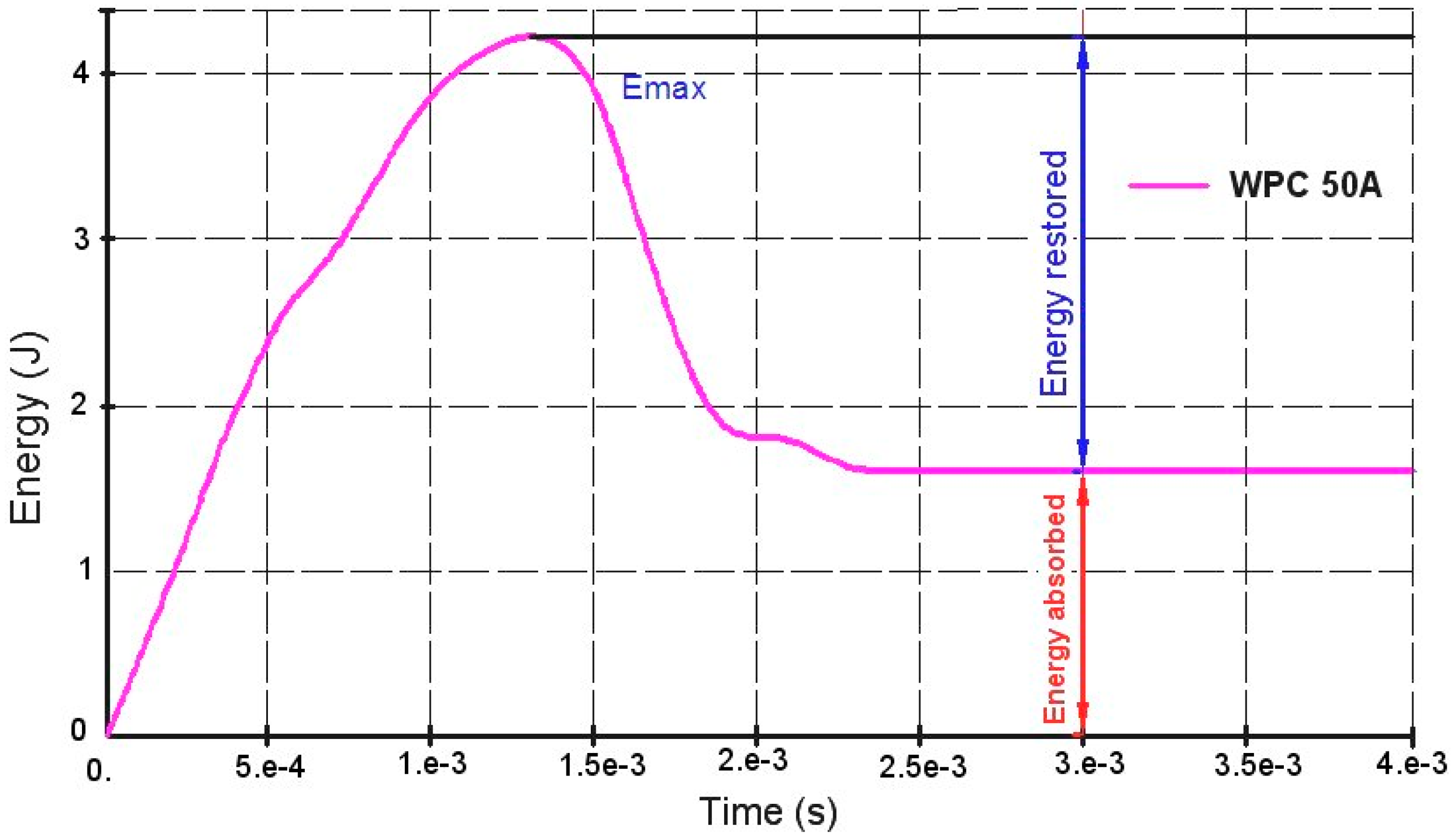
Energy Absorbed during the Impact

The impactor kinetic energy is absorbed by the overall deformation of the plate during the impact, the plastic deformation located in the impact zone, and the rupture, as well as the elastic work. The residual kinetic energy is therefore simply the residual energy of the impactor after impact. In the event that the impactor’s velocity is lower than the ballistic limit, the energy absorbed by the plate is directly the kinetic energy of the impactor ( 1 2 m i V 0 2 ) , with mi being the mass of the impactor and V0 its initial velocity. The deformation energy balance absorbed by the plate is thus established as follows in Equation (6):
W P l a t e T o t a l = W P l a t e K + W E + W P + W F + W D é b r i s K = 1 2 m i ( V 0 2 V B 2 )
  • W P l a t e K : Energy related to the overall deformation of the plate;
  • W E : Elastic deformation energy;
  • W P : Plastic deformation energy;
  • W F : Energy related to internal friction;
  • W D e b r i s K : Kinetic energy transferred to debris induced by the impact the internal energy dissipation through Coulomb friction work and of debris ejection can be assumed negligible in the total energy balance during the impact;
  • WF ≈ 0 (friction between the impactor and the plate is neglected); and
  • W D é b r i s K 0 . Moreover, due to the low impact velocity, only elastic distortions occur; therefore, W p 0 the energy balance reduces to Equation (7), as follows:
    W P l a t e T o t a l = W P l a t e K + W E = 1 2 m i ( V 0 2 V B 2 )

3. Results and Discussion

3.1. Drop Weight Test

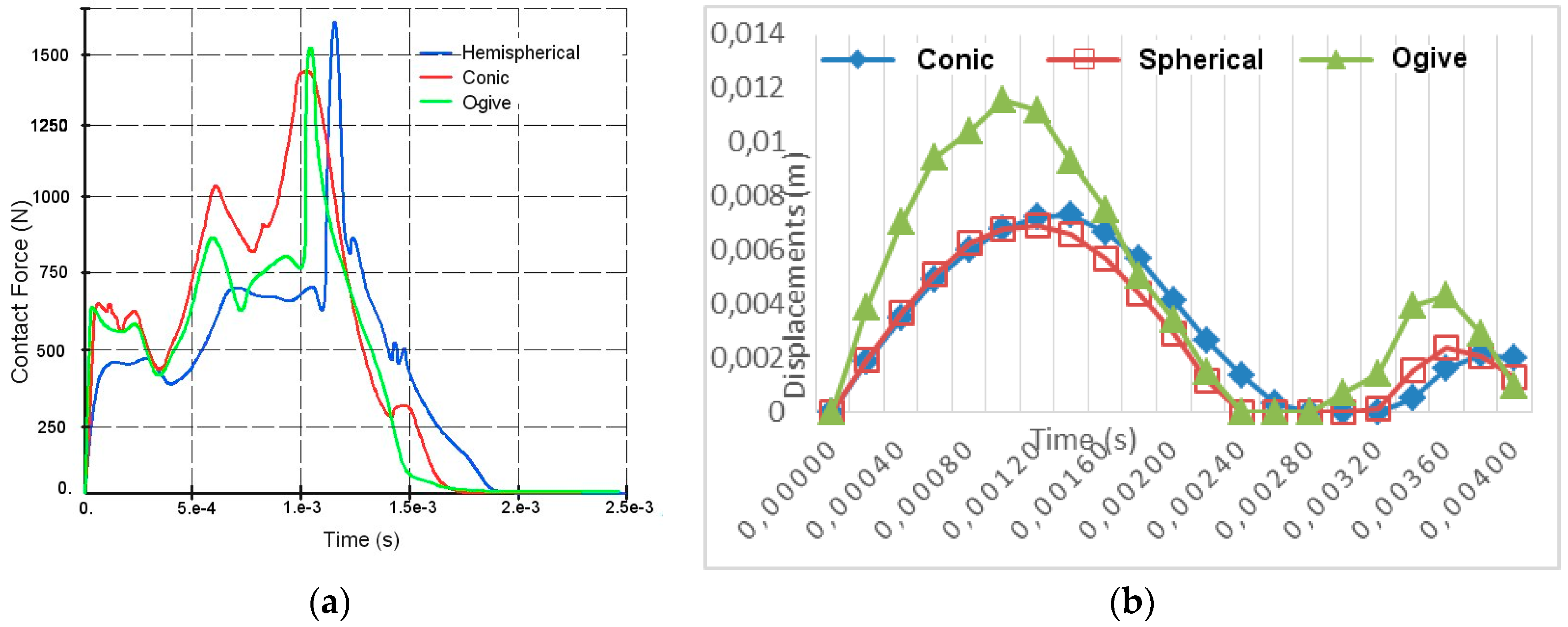
3.1.1. Displacements of the Plate and Impactor

The observation for all of the WPC wood flour wt.% reveals that the plate underwent a perfectly elastic distortion. In addition, important displacement amplitudes were observed for low reinforcement wt.% and for larger speeds (Figure 5).
As a result, the reinforcement of the WPC with wood flour is important in absorbing the impact loading. In addition, a maximum displacement of 9 mm is reached for the 10% reinforced WPC specimen, WPC 10A. This result is higher than that of hybrid composites, as reported in previous studies [19]. In fact, the hybrid specimens reinforced with glass fiber show a very good resistance to impact loading [26,43].
Figure 6 shows the same trend, reflecting the overall behavior of the WPC during impact, namely: the ascending part represents an absorption phase, whereas the descending part indicates a partial restitution phase to the projectile in terms of kinetic energy required for the rebound.

3.1.2. Energy Absorbed

Figure 7a represents the energy curves and shows that the maximum absorbed energy is reached with the WPC 50A and WPC 30A test coupons, with 28% and 26% energy absorption rates of the total energy, respectively (Figure 7b). These results are in agreement with the experiments on hybrid WPC made up of glass fibers, where the energy absorption rate ranges from 24–26% [19].

3.1.3. Impactor’s Rebound Speed

Figure 8a shows that the rebound velocity increases with the wood flour content to reach its maximum at around 20%, after which it decreases with the increasing density of the test specimens.

3.1.4. Effects of the Impactor’s Tip Shape

The results show an almost identical evolution for the three types of impactor’s tip used herein, during the impact and rebound phases. The peak values of the impact force and displacement are probably ascribable to the propagation of elastic waves accompanying the impact. A maximum contact force value of 1680 N is reached for the WPC 50A specimen and for the hemispherical impactor at time 1.15 ms, as seen in Figure 9. Continuous loading beyond that point leads to a continuous increase in damage through the thickness of the WPC plate, which increases with impact load until time 1.15 ms, when there is permanent damage caused to the plate, and hence a decrease in the impact force. The same trend is observed for other impactors. In fact, the conical and ogive impactors produced 1478 N and 1537 N, respectively. It is eventually observed that the principal failure mode here was attributed to bending stress. Table 2 gives a comparative overview of the effects of the impactors used.

3.1.5. Strains and Stresses

We have monitored the deformation field of the WPC plate at regular time intervals of 0.6, 1, and 1.4 ms. The results shown in Table 3 are identical to the conical and ogive impactors, and yet superior to the results of the hemispherical type. Figure 10 and Figure 11 show the maximum strains and equivalent von Mises stresses at the center of the plates, respectively.

3.2. Chapy Impact Test

Figure 12 and Figure 13a represent the time dependence of the absorbed energy obtained from the energy curves of WPC 50A test coupon, from where the Azobé flour content dependence of the toughness curve (Figure 13b) for each specimen is derived.
The absorbed energy being evaluated between the beginning and the end of the equilibrium position of the Charpy pendulum, the amount of energy required for the complete or partial rupture of each test specimen, it is identifiable by the following scheme of principles (Figure 12).
The toughness ranges from 34.8 kJ·m−2 to 34.8 kJ·m−2 (Figure 13b) for the minimum and maximum load rates, respectively. Compared with a hybrid WPCs, the Azobé/UF WPCs absorb less energy before rupture. This difference is certainly due to the fibrous reinforcement of the hybrid WPCs, which enhances the bending performance of the material.

3.3. Discussion

The above FEA results roughly compare well with the known existing experimental results. More accuracy in the simulations could be achieved by the numerical modeling of realistic WPC material structures, including details of the wood anatomy and variations in the structure within the specimens. However, the FEA is a popular continuum method used here to model the WPC particulate material problems. The continuum approach has shown that it can provide useful quantitative information on the macroscopic behavior of particulate materials. The continuum approach can be successful in the simulation of particulate systems, when the size of the particles is much smaller than the entire system [44]. Moreover, continuum models have constitutive equations for bulk materials, which contain some macroscopic parameters. The lack of information about these parameters may limit the application of the continuum method for the study of particulate materials. To account for the material particular structure, Nairn [45] used the material point method (MPM) to perform an analysis of the realistic wood structures. For the WPC material studied herein, numerical discrete element methods (DEM) that have been used [46,47] as an alternative for research involving particulate behavior could be advantageously applied. Apart from the common issues of model formulation and validation, the major constraint on this approach is the number of particles that can be modeled if the computing times are to be kept within the feasible limits. Definitely, numerical investigations need to be pursued, given that the experimental investigations of the behavior of the particulate systems can provide useful information, but are often constrained by the limitations of the measuring methods.

4. Conclusions

The aim of the work presented herein was to study the predictability of the dynamic response of WPCs during the Charpy impact and low-velocity drop weight impact tests. The Az/UF WPC test coupons were used for the parametric investigation based on the FEA simulations performed in ANSYS code. These simulations are aimed at investigating the influence of some geometrical and/or mechanical parameters of the impactor on the global response of the plate during the impact test. The displacements, contact force, energy stresses, and strains were monitored for the wood flour contents in the 0–50 wt.%. The results show that the displacements decrease with increasing the wood filler content, and vary in the 6.8–9 mm interval. From an energetic point of view, the maximum absorbed energy is observed between 40 and 50% of Azobé flour wt.%, with energy absorption rates of 28% and 26% of total energy. These results are in agreement with those reported in previous research work on hybrid WPCs filled of wood flour and glass fibers, producing an energy absorption rate of 24–26%. In addition, an evaluation of the toughness by numerical simulation of the Charpy test shows a decrease compared with the wood flour content in the 34–34.75 kJ·m−2 interval. Unlike the hybrid WPCs, Azobé/UF WPCs absorbs less energy before rupture. In general, the matrix reinforcement plays a major role in the shock dampening of the WPCs. Thus, an increase in the wood flour content decreases the toughness of the composite. Future work will refine the numerical results obtained herein, by using the discrete element method (DEM) for numerical simulations. Laboratory tests on these materials will also be considered in order to validate the numerical results.

Author Contributions

R.N. and J.A.A. designed the study and developed the theoretical framework. S.F.L. carried out the numerical simulations and wrote up the first draft of text in the form of a dissertation in French. R.N. devised the project plan and supervised the research of S.F.L., and T.B. helped with interpreting the results and worked on the manuscript. All of the authors discussed the results and commented on the manuscript.

Funding

This research received no external funding.

Acknowledgments

For their helpful discussion and collaboration, special thanks go to Gnasiri from the computer lab of the Government Technical Professional Training Center of Ndog Bati, Douala.

Conflicts of Interest

The authors declare no conflict of interest.

References

  1. Shin, K.B.; Lee, J.Y.; Cho, S.H. An experimental study of low-velocity impact responses of sandwich panels for Korean low floor bus. Compos. Struct. 2008, 84, 228–240. [Google Scholar] [CrossRef]
  2. Grubbström, G.; Oksman, K. Influence of wood flour moisture content on the degree of silane-crosslinking and its relationship to structure–property relations of wood–thermoplastic composites. Compos. Sci. Technol. 2009, 69, 1045–1050. [Google Scholar] [CrossRef]
  3. Kazemi Najafi, S. Use of recycled plastics in wood plastic composites—A review. Waste Manag. 2013, 33, 1898–1905. [Google Scholar] [CrossRef] [PubMed]
  4. Schonberg, W.P. A Rupture Limit Equation for Pre-Loaded Laminated Composite Plates. J. Compos. Sci. 2018, 2, 3. [Google Scholar] [CrossRef]
  5. Schonberg, W.; Schäfer, F.; Putzar, R. Hypervelocity impact response of honeycomb sandwich panels. Acta Astronaut. 2010, 66, 455–466. [Google Scholar] [CrossRef]
  6. Pilarski, J.M.; Matuana, L.M. Durability of wood flour-plastic composites exposed to accelerated freeze-thaw cycling. II. High density polyethylene matrix. J. Appl. Polym. Sci. 2006, 100, 35–39. [Google Scholar] [CrossRef]
  7. Dányádi, L.; Janecska, T.; Szabó, Z.; Nagy, G.; Móczó, J.; Pukánszky, B. Wood flour filled PP composites: Compatibilization and adhesion. Compos. Sci. Technol. 2007, 67, 2838–2846. [Google Scholar] [CrossRef] [Green Version]
  8. Haro, E.E.; Szpunar, J.A.; Odeshi, A.G. Dynamic and ballistic impact behavior of biocomposite armors made of HDPE reinforced with chonta palm wood (Bactris gasipaes) microparticles. Def. Technol. 2018, 14, 238–249. [Google Scholar] [CrossRef]
  9. Ghahri, S.; Kazemi Najafi, S.; Mohebby, B.; Tajvidi, M. Impact strength improvement of wood flour–recycled polypropylene composites. J. Appl. Polym. Sci. 2012. [Google Scholar] [CrossRef]
  10. Stark, N.M.; Service, F.; Rowlands, R.E. Effects of Wood Fiber Characteristics on Mechanical Properties of Wood/Polypropylene Composites. Wood Fiber Sci. 2003, 35, 167–174. [Google Scholar]
  11. Dobreva, D.; Nenkova, S.; Vasileva, S. Morphology and Mechanical Properties of Polypropylene-Wood Flour Composites. Bioresources 2006, 1, 209–219. [Google Scholar]
  12. Puech, L.; Ramakrishnan, K.R.; Le Moigne, N.; Corn, S.; Slangen, P.R.; Le Duc, A.; Boudhani, H.; Bergeret, A. Investigating the impact behaviour of short hemp fibres reinforced polypropylene biocomposites through high speed imaging and finite element modelling. Compos. Part A Appl. Sci. Manuf. 2018, 109, 428–439. [Google Scholar] [CrossRef]
  13. Dhakal, H.N.; Zhang, Z.Y.; Bennett, N.; Reis, P.N.B. Low-velocity impact response of non-woven hemp fibre reinforced unsaturated polyester composites: Influence of impactor geometry and impact velocity. Compos. Struct. 2012, 94, 2756–2763. [Google Scholar] [CrossRef]
  14. De Oliveira Braga, F.; Bolzan, L.T.; Lima, É.P.; Monteiro, S.N. Performance of natural curaua fiber-reinforced polyester composites under 7.62 mm bullet impact as a stand-alone ballistic armor. J. Mater. Res. Technol. 2017, 6, 323–328. [Google Scholar] [CrossRef]
  15. Omar, M.F.; Md Akil, H.; Ahmad, Z.A.; Mazuki, A.A.M.; Yokoyama, T. Dynamic properties of pultruded natural fibre reinforced composites using Split Hopkinson Pressure Bar technique. Mater. Des. 2010, 31, 4209–4218. [Google Scholar] [CrossRef]
  16. Cerbu, C. Aspects concerning to the impact charpy testing in case of composites materials filled with wood flour. In The 4th International Conference Advanced Composite Materials Engineering (COMAT); Transilvania University: Brasov, Romania, 2012. [Google Scholar]
  17. Teng, X.; Wierzbicki, T. Evaluation of six fracture models in high velocity perforation. Eng. Fract. Mech. 2006, 73, 1653–1678. [Google Scholar] [CrossRef]
  18. ASTM International. Standard Test Methods for Determining the Charpy Impact Resistance of Notched Specimens of Plastics; ASTM International: West Conshohocken, PA, USA, 1997; pp. 1–14. [Google Scholar]
  19. Stan, G.I.; Cerbu, C.; Dogaru, F.; Curtu, I. Impact Testing of the Panels Made of Composite Materials Reinforced with Woven Glass Fabric and Wood Flour. Proligno 2011, 7, 39–45. [Google Scholar]
  20. Jeon, K.W.; Shin, K.B. An experimental investigation on low-velocity impact responses of sandwich panels with the changes of impact location and the wall partition angle of honeycomb core. Int. J. Precis. Eng. Manuf. 2012, 13, 1789–1796. [Google Scholar] [CrossRef]
  21. David-West, O.S.; Alexander, N.V.; Nash, D.H.; Banks, W.M. Energy absorption and bending stiffness in CFRP laminates: The effect of 45° plies. Thin-Walled Struct. 2008, 46, 860–869. [Google Scholar] [CrossRef] [Green Version]
  22. Hoo Fatt, M.S.; Sirivolu, D. A wave propagation model for the high velocity impact response of a composite sandwich panel. Int. J. Impact Eng. 2010, 37, 117–130. [Google Scholar] [CrossRef]
  23. Kolopp, A.; Rivallant, S.; Bouvet, C. Impact Testing of Composite Sandwich Structures for Aircraft Armor Applications. In Proceedings of the JNC 17, Poitiers, France, June 2011. [Google Scholar]
  24. Abrate, S. Impact on Composite Structures; Cambridge University Press: Cambridge, UK, 2009. [Google Scholar]
  25. Sutcliffe, M.P.F.; Monroy Aceves, C.; Stronge, W.J.; Choudhry, R.S.; Scott, A.E. Moderate speed impact damage to 2D-braided glass-carbon composites. Compos. Struct. 2012, 94, 1781–1792. [Google Scholar] [CrossRef]
  26. Venkatanarayanan, P.S.; Stanley, A.J. Intermediate velocity bullet impact response of laminated glass fiber reinforced hybrid (HEP) resin carbon nano composite. Aerosp. Sci. Technol. 2012, 21, 75–83. [Google Scholar] [CrossRef]
  27. EN 1522:1998. Windows, Doors, Shutters and Blinds—Bullet Resistance—Requirements and Classification; European Standard; British Standards Institution: London, UK, 1998. [Google Scholar]
  28. Wilkins, M.L. Mechanics of penetration and perforation. Int. J. Eng. Sci. 1978, 16, 793–807. [Google Scholar] [CrossRef]
  29. Goldsmith, W. Non-ideal projectile impact on targets. Int. J. Impact Eng. 1999, 22, 95–395. [Google Scholar] [CrossRef]
  30. Evci, C.; Gülgeç, M. An experimental investigation on the impact response of composite materials. Int. J. Impact Eng. 2012, 43, 40–51. [Google Scholar] [CrossRef]
  31. Boria, S.; Scattina, A.; Belingardi, G. Impact behavior of a fully thermoplastic composite. Compos. Struct. 2017, 167, 63–75. [Google Scholar] [CrossRef]
  32. Banerjee, P.; Karpenko, O.; Udpa, L.; Haq, M.; Deng, Y. Prediction of impact-damage growth in GFRP plates using particle filtering algorithm. Compos. Struct. 2018, 194, 527–536. [Google Scholar] [CrossRef]
  33. Safri, S.N.A.; Sultan, M.T.H.; Aminanda, Y. Impact characterisation of Glass Fibre Reinforced Polymer (GFRP) type C-600 and E-800 using a drop weight machine. Appl. Mech. Mater. 2014, 629, 461–466. [Google Scholar] [CrossRef]
  34. Sutherland, L.S.; Guedes Soares, C. Impact characterisation of low fibre-volume glass reinforced polyester circular laminated plates. Int. J. Impact Eng. 2005, 31, 1–23. [Google Scholar] [CrossRef]
  35. Hirai, Y.; Hamada, H.; Kim, J.-K. Impact response of woven glass-fabric composites—I: Effect of fibre surface treatment. Compos. Sci. Technol. 1998, 58, 91–104. [Google Scholar] [CrossRef]
  36. Christoforou, A.P. Impact dynamics and damage in composite structures. Compos. Struct. 2001, 52, 181–188. [Google Scholar] [CrossRef]
  37. Sutherland, L.S.; Guedes Soares, C. The effects of test parameters on the impact response of glass reinforced plastic using an experimental design approach. Compos. Sci. Technol. 2003, 63, 1–18. [Google Scholar] [CrossRef]
  38. Lee, S.-M.; Cheon, J.-S.; Im, Y.-T. Experimental and numerical study of the impact behavior of SMC plates. Compos. Struct. 1999, 47, 551–561. [Google Scholar] [CrossRef]
  39. Dear, J.P.; Brown, S.A. Impact damage processes in reinforced polymeric materials. Compos. Part A Appl. Sci. Manuf. 2003, 34, 411–420. [Google Scholar] [CrossRef]
  40. Espinosa, C. Contribution à L’étude du Comportement sous Impact Localisé Basse Vitesse de Plaques Stratifiées à Base D’unidirectionnels Composites à Fibres Longues. Ph.D. Thesis, Université de Bordeau I, Bordeaux, France, 1991. [Google Scholar]
  41. Anderson, C.E., Jr. Analytical models for penetration mechanics: A Review. Int. J. Impact Eng. 2017, 108, 3–26. [Google Scholar] [CrossRef]
  42. Abanda, G.-C.; Ntenga, R. Comportement physico-mécanique des composites bois-polymère à base d’essences tropicales africaines. Sci. Technol. Dév. 2016, 17, 113–116. [Google Scholar]
  43. Sevkat, E.; Liaw, B.; Delale, F. Drop-weight impact response of hybrid composites impacted by impactor of various geometries. Mater. Des. 2013, 52, 67–77. [Google Scholar] [CrossRef]
  44. Cundall, P.A.; Hart, R.P. Numerical Modelling of Discontiniua. Eng. Comput. 1992, 9, 101–113. [Google Scholar] [CrossRef]
  45. Nairn, J.A. Numerical Simulations of Transverse Compression and Densification In Wood. Wood Fiber Sci. 2006, 38, 576–591. [Google Scholar]
  46. Favier, J.; Kremmer, M.; Abbaspour-fard, H.; Raji, A.O. Shape Representation of Axi-Symmetrical, Non-Spherical Particles in Discrete Simulations Using Multi-Element Model Particles. Eng. Comput. 1999, 16, 467–480. [Google Scholar] [CrossRef]
  47. Favier, J.; Kremmer, M.; Abbaspour-fard, H. Discrete Element Modelling of the Flow of Irregular, Smooth-Surfaced Particles Through an Environment of Arbitrary Geometry. In Proceedings of the Fourteenth Engineering Mechanics Conference, Austin, TX, USA, 21–24 May 2000. [Google Scholar]
Figure 1. The modeled drop weight tests in the wood plastic composite (WPC) plate.
Jcs 02 00060 g001
Figure 2. Applied initial and boundary conditions.
Jcs 02 00060 g002
Figure 3. Geometry, shapes, and dimensions of impactors for (a) hemispheric, (b) conic 55°, (c) conic 90°, or Ogive.
Jcs 02 00060 g003
Figure 4. The WPC specimen model and impactor tip used for the Charpy impact test (CIT) test. Initial and boundary conditions on the Charpy V-notch (CVN) specimen.
Jcs 02 00060 g004
Figure 5. Variation of the displacement during impact (a) of the impactor and (b) of the WPC 10A plate.
Jcs 02 00060 g005
Figure 6. Energy balance during the impact.
Jcs 02 00060 g006
Figure 7. Absorbed energy (a) energy absorption rate (b) for each fabricated Azobé/UF WPC specimen.
Jcs 02 00060 g007
Figure 8. Wood flour content dependence of (a) impactor’s rebound velocity (b) WPC density.
Jcs 02 00060 g008
Figure 9. Time dependence of (a) the impactor’s contact force and (b) the impactor’s displacement.
Jcs 02 00060 g009
Figure 10. Maximum strains at the center of the plate.
Jcs 02 00060 g010
Figure 11. Equivalent stress at the center of the plate.
Jcs 02 00060 g011
Figure 12. Time dependence of energy absorbed during the Charpy impact.
Jcs 02 00060 g012
Figure 13. CIT Energy as (a) a function of time and (b) Azobé flour content.
Jcs 02 00060 g013
Table 1. Physical properties of different Azobé/urea formaldehyde (UF) wood plastic composite (WPC) formulations used.
WPC Specimen ρ   ( k g / m 3 ) E 1 E 2 E 3 G 1 G 2 G 3 ν 1 ν 2 ν 3
WPC 0A852.1288.9390.8288.9120.4162.8120.40.20.20.2
WPC 10A700313.2292.7313.2130.5121.9130.50.20.20.2
WPC 20A666.7508.7315.9508.7211.9131.62211.90.20.20.2
WPC 30A1000313.3337.1313.3122.4131.7122.40.20.20.2
WPC 40A1125307.6535.8307.6120.2209.3120.20.20.20.2
WPC 50A1285.7429.4379.9429.4178.9158.3178.90.20.20.2
Table 2. Comparative effects impactors, displacement contact force and energy produced. “+”, ”++”, and “+++” used for low, moderate, and high values, respectively.
Type of ImpactorDisplacementsContact ForceEnergy
Hemispherical+++++++
Conical+++++
Ogive++++++
Table 3. State of the deformations of the WPC 50A composite plate observed at regular intervals of 0.4 ms for each type of impactor.
Impactor0.6 ms1 ms1.4 ms
Hemispherical Jcs 02 00060 i001 Jcs 02 00060 i002 Jcs 02 00060 i003
Conic Jcs 02 00060 i004 Jcs 02 00060 i005 Jcs 02 00060 i006
ogive Jcs 02 00060 i007 Jcs 02 00060 i008 Jcs 02 00060 i009

