Article

Effect of Carbon Nanotube Deposition Time to the Surface of Carbon Fibres on Flexural Strength of Resistance Welded Carbon Fibre Reinforced Thermoplastics Using Carbon Nanotube Grafted Carbon Fibre as Heating Element

Department of Biomedical Engineering, Doshisha University, Kyoto 602-8580, Japan
*
Author to whom correspondence should be addressed.
J. Compos. Sci. 2019, 3(1), 9; https://doi.org/10.3390/jcs3010009
Submission received: 10 November 2018 / Revised: 3 January 2019 / Accepted: 8 January 2019 / Published: 12 January 2019

Abstract

:
In recent years, carbon fibre reinforced thermoplastics (CFRTP) are expected to be used as lightweight structural materials for mass-produced vehicles. CFRTP with thermoplastics as matrix allows us to weld them using melting of matrix by heating. We have been developing a direct resistance heating method, which uses carbon fibres as the resistance heating element. Carbon nanotube (CNT) is expected to be used as additive to FRP and we reported that the fibre/matrix interfacial shear strength was improved by grafting CNT on the surface of carbon fibres and tensile lap-shear strength was improved by using CNT grafted carbon fibre as the heating element for welding. For the practical use of CFRTP for structural parts, flexural strength is also necessary to be evaluated. In this study, flexural test was carried out to clarify the effect of CNT deposition time to the surface of carbon fibres on flexural strength of resistance welded CFRTP using CNT grafted carbon fibre as the heating element. The highest flexural strength was obtained when CNT10, for which CNT is grafted on the carbon fibres for deposition time of 10 min, was used for the heating element of resistance welding. In the case of CNT deposition time of 60 min, the lowest flexural strength was obtained because of the poor impregnation of the resin into the carbon fibre due to the excess CNT on the carbon fibres.

1. Introduction

In recent years, carbon dioxide emission regulations for automobiles have become severer and improvement of fuel efficiency technology is urgently required. Lightening the weight of the vehicle is one of the solutions to improve the fuel efficiency. Carbon fibre reinforced plastics (CFRP) are expected to be used as lightweight materials in mass-produced products from the point that CFRP is superior in specific strength and specific stiffness [1]. In particular, Carbon fibre reinforced thermoplastics (CFRTP) are expected to be applied to mass-produced products from the point that CFRTP is superior in shock resistance, recycling property and productivity [2,3,4]. CFRTP can be moulded in an integrated complex structure, while many joints exist in real production. Fastening methods using bolts and rivets are generally applied in metal joining [5]. As these methods need holes and fasteners, which cause stress concentration and weight gain [6,7], the joining methods without metal joints are expected to be developed. In regard to the joining of CFRTP, CFRTP with thermoplastics as matrix allows us to weld them using melting of the matrix by heating [8]. We have been developing a direct resistance heating method which uses carbon fibres as the resistance heating element [9]. Further improvement of welding strength is needed to reduce the welding area where materials overlap. Carbon nanotube (CNT) is in the diameter order of nanometres and superior in mechanical property, electrical conductivity and thermal conductivity and CNT is expected to be used as an additive agent to fibre reinforced plastics (FRP) [10,11]. We reported that the fibre/matrix interfacial shear strength was improved by grafting CNT on the surface of the carbon fibres [12,13] and tensile lap-shear strength was improved by using CNT grafted carbon fibre as the heating element for welding because of the improvement of the interfacial shear strength by CNT deposition on the surface of the carbon fibres [9]. In the joined material, not only tensile lap-shear tests but also flexural tests are carried out to evaluate the mechanical characteristics [14]. As CNT grows in the normal direction of the surface of the carbon fibres, shear load is applied in tensile lap-shear tests. On the contrary, tensile load is applied to CNT in the flexural tests. Since the effect on the mechanical properties of CNT grafting on the carbon fibre may differ between tensile lap-shear tests and flexural tests, flexural strength is also necessary to be evaluated for the practical use of CFRTP for structural parts.
In this study, flexural test was carried out to clarify the effect of CNT deposition time to the surface of carbon fibres on the flexural strength of resistance welded CFRTP using CNT grafted carbon fibre as the heating element.

2. Materials and Methods

2.1. Materials

Unidirectional spread carbon fibre tow (Nippon Tokushu Fabric Inc., Katsuyama, Japan, 70 mm long, 12.5 mm wide and 0.03 mm thick, referred to as As-received) was used as a heating element and one layer of the spread carbon fibre tow was used for the heating element. Polyamide film (PA, PA6, 1013B, Ube Industries, Ltd., Tokyo, Japan, 40 µm thick, 225 °C M.P.) was used for the matrix of the bonding area. CFRTP laminated plates were moulded by a press and injection hybrid moulding machine (Satoh Machinery Works Co., Ltd., Nagoya, Japan), using two sheets of CFRTP laminated plate (Maruhachi Co., Ltd., Fukui, Japan, 210 g/m2, volume fraction 40%, [0°/90°]2s, 1 mm thick). As for the moulding conditions: moulding temperature was set at 280 °C, moulding time was set for 8 min and moulding pressure was set to 2 MPa as in our previous studies [15,16]. The specimens of 100 mm long, 25 mm wide and 2 mm thick were cut out from the CFRTP laminates with 0 degree for the longitudinal direction of the outermost layer of the specimen.

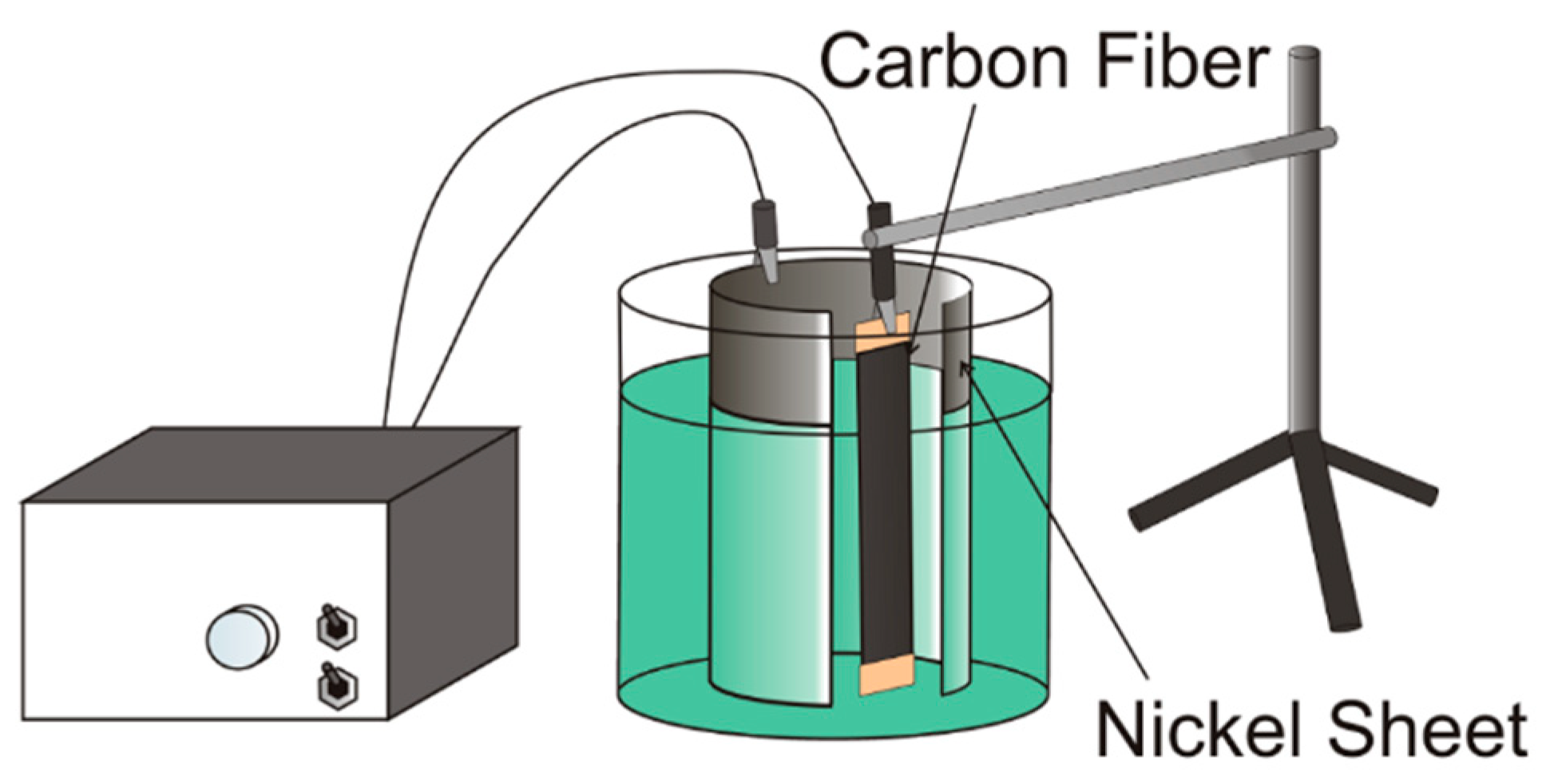
2.2. Method of CNT Deposition

The CNT deposition on the surface of carbon fibre was carried out in Chemical Vapor Deposition by a CVD apparatus (MPCVD-70, Microphase Co., Ltd., Tsukuba, Japan) as shown in Figure 1. Ethanol was used as the carbon source. Ni was plated as the catalyst on the surface of carbon fibre by electro Ni plating with the current of 0.3 A and the plating time of 15 s as shown in Figure 2. The Ni plating bath (watt bath) consists of 240 g/L of Nickel sulphate hexahydrate (NiSO4·6H2O), 45 g/L of Nickel chloride hexahydrate (NiCl2·6H2O) and 30 g/L of Boracic acid (H3BO3). The deposition conditions of CNT were under vacuum at 600 °C for 10 min, 30 min and 60 min. CNT grafted carbon fibres with deposition times of 10 min, 30 min and 60 min are referred to as CNT10, CNT30 and CNT60, respectively. CNT grafted carbon fibre was observed with a Scanning Electron Microscope (SEM, JSM-6390LT, JEOL, Tokyo, Japan) and the average diameter was calculated from the SEM images by dividing the external area of a CNT grafted carbon fibre by its longitudinal length.

2.3. Resistance Welding Methods and Flexural Test

Figure 3 shows the schematic drawing of the experimental setup for resistance welding. Between the two CFRTP specimens, As-received or CNT grafted carbon fibre, as the heating element, is stacked in between two layers of PA films with a welding length of 12.5 mm. For the power supply to the heating element, a high frequency power supply unit (T162-6014AAH, Thamway Co., Ltd., Fuji, Japan) and impedance converter (T010-6012A, Thamway Co., Ltd., Fuji, Japan) were used at the frequency of 20 kHz and the output power of 70 W. After applying the pressure of 2 MPa by using a universal testing machine (AGX-250kN, Shimadzu Co., Ltd., Kyoto, Japan), the energization was applied for 1 min and the welded specimen was air-cooled for 30 s under the pressure of 2 MPa.
As shown in Figure 4, the temperature history of the heating element itself was measured with a thermograph (R300SR-H, Nippon Avionics Co., Ltd., Tokyo, Japan) when the same output power was applied. During the welding process, the temperature history of the welded zone was measured with a type K thermocouple and a data logger (Portable Multi Logger, Omron Co., Kyoto, Japan) between the CFRTP laminated plate and PA film as shown in Figure 5. The thermograph was also used to measure the temperature history of the welded zone.
The cross-section of the welded zone was polished by a Cross-section Polisher (SM-09010, JEOL Ltd., Japan) at the accelerating voltage of 5 kV and the polishing time of 12 h and observed by a digital microscope (VHX-5000, Keyence Co., Osaka, Japan) and the SEM.
Flexural test was conducted based on JIS (Japan Industrial Standard) K 6856 by using a universal testing machine (5566, Instron Japan Co., Ltd., Kawasaki, Japan) as shown in Figure 6. The span length was 38 mm and the displacement velocity was 1.7 × 10⁻⁵ m/s. The flexural strength was obtained by dividing the maximum load by the welding area based on JIS K 6856.

3. Results and Discussion

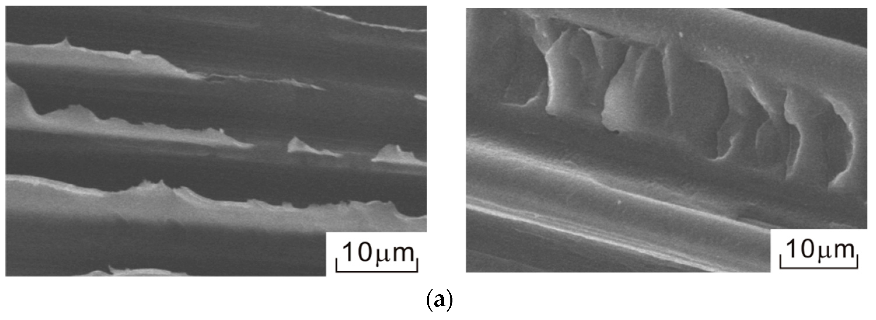
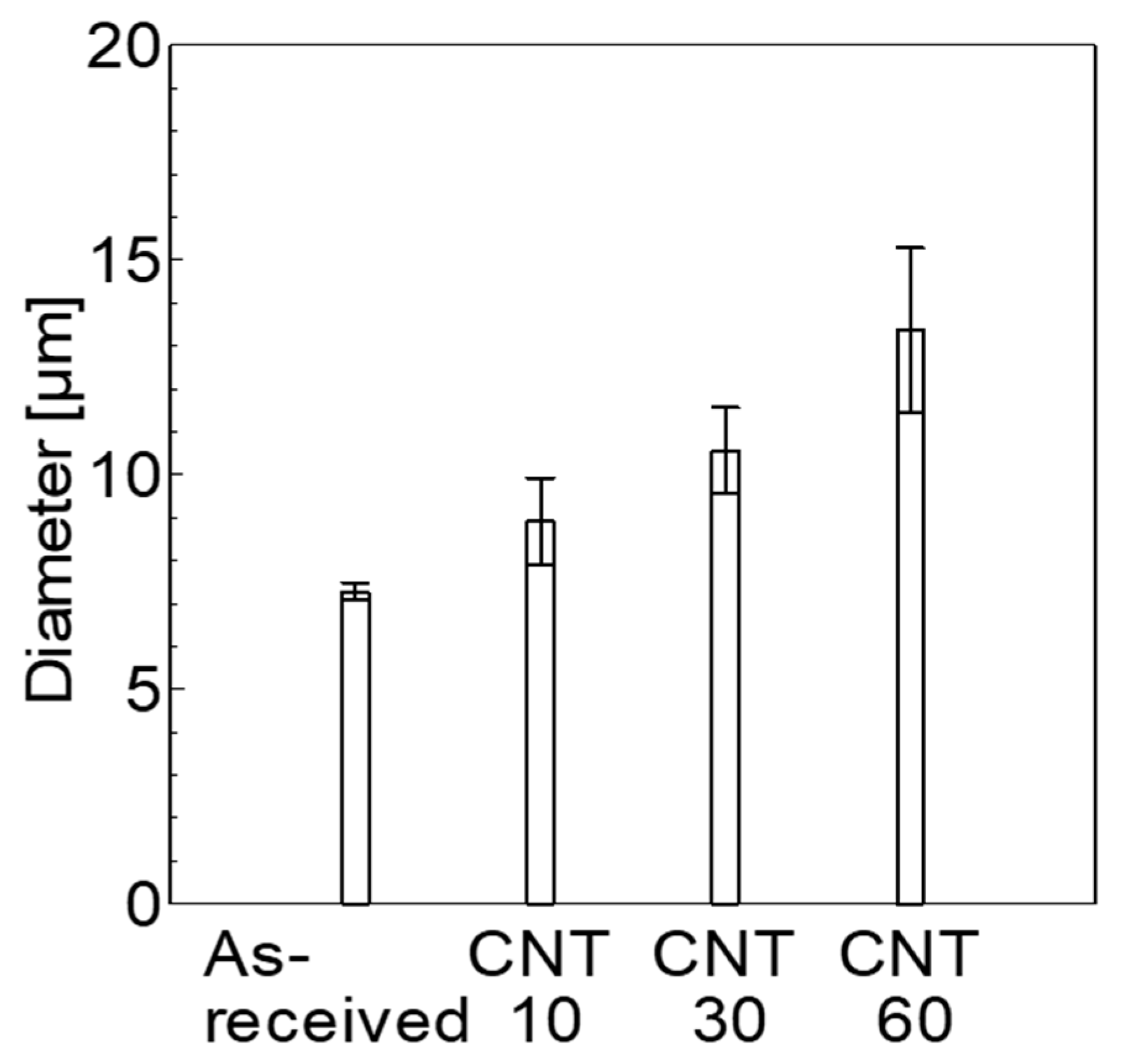
3.1. CNT Deposition to Surface of Carbon Fibre

Figure 7 shows the SEM images of As-received and CNT grafted carbon fibre at different deposition times. Some Ni particles were observed on the tip of CNTs in CNT10. In contrast, fewer Ni particles were observed on the tip of CNTs in CNT30 and CNT60. It is reported that CNT grafts by pushing up the metal particle (tip growth model) (Figure 8a) or growing up with the metal particles rooted on the surface of the substrate (base growth model) (Figure 8b) [17,18,19,20,21,22]. When the interaction strength between the catalyst and the substrate is weak, the carbon precursor decomposes into the carbon atom on the top surface of the catalyst particle, then the carbon atom diffuses down through the catalyst and the CNTs grow from the bottom of the catalyst, thus pushing the whole the catalyst away from the substrate. On the other hand, when the interaction strength between the catalyst and the substrate is strong, the decomposition of the carbon precursor and the diffusion of the carbon atom are similar to those of the tip growth model. However, the carbon atoms firstly form the hemispherical dome on the top of the catalyst, which grows in the form of seamless cylindrical graphitic to form the CNTs. Hence, the catalyst fixes on the base to support the growth of the CNTs [17,18,19,20,21,22]. In addition, it is reported that when the deposition time of CNT increases, the weight of CNT also increases but the growth length rate of CNT slows down [12]. It seems that CNT grows with curving. In the specimen of CNT10, some Ni particles were observed on the tip of CNTs. It seems that some Ni particles were observed in CNT10 because CNT grafted by pushing up the Ni particle. On the other hand, fewer Ni particles were observed on the tip of CNTs in the specimens of CNT30 and CNT60. It seems that fewer Ni particles were observed on the outermost layer of the carbon fibre in CNT30 and CNT60 because CNT grew with curving as bowed its head. This is the main reason for fewer particles being observed on CNT30 and CNT60.
Figure 9 shows the average diameter of As-received, CNT10, CNT30 and CNT60. The average diameter of CNT grafted carbon fibre became larger as the deposition time of CNT became longer.

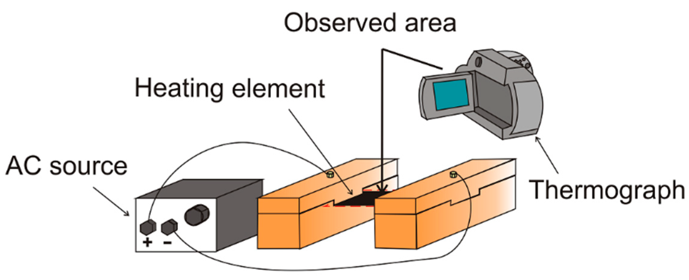
3.2. Temperature History of the Heating Elements and Welded Zone

Figure 10 shows the temperature history of As-received and CNT30, one of the CNT grafted carbon fibres for comparison with As-received, when the output power was applied to these heating elements. The reached temperature of CNT30 was higher than As-received. It is reported that CNT grafted carbon fibre showed low electric resistance value because the cross-section area of the carbon fibre bundles became large by deposition of CNT and showed high Joule heat because of low electric resistance in direct current [23]. In this study, while an alternating current power was used instead of direct current, the same tendency, the reached temperature of CNT grafted carbon fibre is higher than As-received, was obtained.
Figure 11 shows the temperature history of the welded zone measured by the type K thermocouple during the welding process. There was no significant difference in the temperature history between As-received, CNT10, CNT30 and CNT60. Figure 12 shows the thermal image of the welded zone measured by the thermograph. No effect of CNT deposition on the temperature history was observed because the generated heat of the heating element transfers to the polyamide film and CFRTP specimens.

3.3. Flexural Test of Welded Specimens

Figure 13 shows the digital microscope image and SEM image of the cross-section of the welded zone of CNT10 and Figure 14 shows the SEM images of the cross-sections of the welded zone of As-received, CNT10 and CNT60. The SEM images are the magnified images of the heating element of the cross-sections of the welded zone in the digital microscope images. In the specimens of As-received and CNT10, there were no voids. In contrast, in the specimen of CNT60, there were many voids between the CNT grafted carbon fibre and matrix. Due to the excess CNT on the carbon fibres in the case of CNT60, the resin was difficult to impregnate between CNTs.
Figure 15 shows the flexural strengths of the welded specimens. The highest flexural strength was obtained when CNT10 was used for the heating element of resistance welding and the lowest flexural strength was obtained when CNT60 was used. There was no significant difference in the flexural strength between As-received and CNT30. Figure 16 shows the SEM images of the fracture surfaces of flexural tests of the welded specimens. For the specimen of As-received, the resin was stretched after the carbon fibre was pulled out. The specimen of As-received showed lower fibre/matrix interfacial strength. Meanwhile, for the specimen of CNT10, CNT and the resin were observed on the surface of the carbon fibre. This suggests that the fracture occurred in the fibre/matrix interface for As-received and at the outermost layer of the resin for CNT10. It is reported that the interfacial shear strength was improved by deposition of CNT on the surface of the carbon fibres [12,13]. Due to the higher fibre/matrix interfacial strength, CNT10 showed the highest flexural strength. On the other hand, it is assumed that CNT60 showed the lowest flexural strength because of the poor impregnation of the resin into the carbon fibre due to the excess CNT on the carbon fibres.
Although Mode I type crack opening at the edge of the bonding is considered to be the main fracture mode in the flexural tests used in this study, the hackles, which were caused by shear stress under Mode II, were microscopically observed on the fracture surface shown in Figure 16a. In the tensile lap-shear tests, we have reported that the tensile lap-shear strength is improved by CNT deposition on the surface of the carbon fibres due to the anchoring effect of CNT [9]. Similar to the results of the tensile lap-shear tests, resistance welded CFRTP using CNT grafted carbon fibre as the heating element showed higher flexural strength.

4. Conclusions

CNT grafted carbon fibre was used as the heating element of resistance welding and the effect of CNT deposition time to the surface of carbon fibres on the flexural strength of resistance welded CFRTP was evaluated. The investigation yielded the following conclusions:
  • Some Ni particles were observed on the tip of CNTs in CNT10. In contrast, fewer Ni particles were observed on the tip of CNTs in CNT30 and CNT60. CNT grows with curving.
  • The reached temperature became higher by CNT deposition to the surface of the carbon fibres in the temperature history of the heating element. In contrast, there was no significant difference between As-received and CNT grafted carbon fibres by heat transfer in the temperature history of the welded zone.
  • The highest flexural strength was obtained when CNT grafted carbon fibre grafted at the deposition time of 10 min was used for the heating element of resistance welding. This is due to improvement of the interfacial strength by deposition of CNT on the surface of carbon fibres. The result of the flexural tests shows the same tendency as the results in the tensile lap-shear tests that the tensile lap-shear strengths of CNT grafted carbon fibres are higher than As-received.

Author Contributions

Conceptualization, K.T.; Methodology, K.T.; Investigation, T.N. and K.A.; Writing-Original Draft Preparation, T.N.; Writing-Review & Editing, K.T.; Supervision, T.K.; Project Administration, K.T.; Funding Acquisition, K.T. and T.K.

Funding

This work was partially supported by KAKENHI (Japan Society for the Promotion of Science, Grant-in-Aid for Scientific Research (B))(26289011) and a research project on “Research and Development Center for Advanced Composite Materials” of Doshisha University and MEXT (the Ministry of Education, Culture, Sports, Science and Technology, Japan)—Supported Program for the Strategic Research Foundation at Private Universities, 2013-2017, the project S1311036.

Conflicts of Interest

The authors declare no conflict of interest.

References

  1. Ishikawa, T. Overview of Carbon Fiber Reinforced Composites (CFRP) Applications to Automotive Structural Parts,—Focussed on Thermoplastic CFRP—. J. JSPE 2015, 81, 489–493. [Google Scholar]
  2. Wong, K.H.; Mohammed, S.D.; Pickering, S.J.; Brooks, R. Effect of coupling agents on reinforcing potential of recycled carbon fibre for polypropylene composite. Compos. Sci. Technol. 2012, 72, 835–844. [Google Scholar] [CrossRef]
  3. Doufnoune, R.; Chebira, F.; Haddaoui, N. Effect of titanate coupling agent on the mechanical properties of calcium carbonate filled polypropylene. Int. J. Polym. Mater. Polym. 2003, 52, 967–984. [Google Scholar] [CrossRef]
  4. Marsh, G. Reinforced thermoplastics, the next wave? Reinf. Plast. 2014, 58, 24–28. [Google Scholar] [CrossRef]
  5. Kolesnikov, B.; Herbeck, L.; Fink, A. CFRP/titanium hybrid material for improving composites bolted joints. Compos. Struct. 2008, 83, 368–380. [Google Scholar] [CrossRef]
  6. Amancio-Filho, S.T.; dos Santos, J.F. Joining of polymers and polymer-metal hybrid structures: Recent developments and trends. Polym. Eng. Sci. 2009, 49, 1461–1476. [Google Scholar] [CrossRef]
  7. Kumar, S.B.; Sridhar, I.; Sivashanker, S.; Osiyemi, S.O.; Bag, A. Tensile failure of adhesively bonded CFRP composite scarf joints. Mater. Sci. Eng. B 2006, 132, 113–120. [Google Scholar] [CrossRef]
  8. Costa, A.P.; Botelho, E.; Costa, M.L.; Narita, N.E.; Tarpani, J.R. A review of welding technologies for thermoplastic composites in aerospace applications. JATM 2012, 4, 255–265. [Google Scholar] [CrossRef]
  9. Tanaka, K.; Tanaka, Y.; Katayama, T. Effect of carbon nanotube grafting on tensile shear strength of resistance welded CFRTP. J. Soc. Mater. Sci. 2016, 65, 727–732. [Google Scholar] [CrossRef]
  10. Gojny, F.H.; Wichmann, M.H.G.; Fiedler, B.; Bauhofer, W.; Schulte, K. Influence of nano-modification on the mechanical and electrical properties of conventional fibre-reinforced composites. Compos. Part A-Appl. Sci. Manuf. 2005, 36, 1525–1535. [Google Scholar] [CrossRef]
  11. Ma, P.C.; Siddiqui, N.A.; Marom, G.; Kim, J.-K. Dispersion and functionalization of carbon nanotubes for polymer-based nanocomposites: A review. Compos. Part A-Appl. Sci. Manuf. 2010, 41, 1345–1367. [Google Scholar] [CrossRef]
  12. Tanaka, K.; Okumura, Y.; Katayama, T.; Morita, Y. Effect of carbon nanotubes deposition form on carbon fiber and polyamide resin interfacial strength. J. Soc. Mater. Sci. 2016, 65, 586–591. [Google Scholar] [CrossRef]
  13. Yumitori, S.; Arao, Y.; Tanaka, T.; Naito, K.; Tanaka, K.; Katayama, T. Increasing the interfacial strength in carbon fiber/polypropylene composites by growing CNTs on the fibers. WIT Trans. Model. Simul. 2013, 55, 275–284. [Google Scholar] [Green Version]
  14. Rezvaninasab, M.; Farhadinia, M.; Mirzaei, A.; Ramzaninezhad, M.; Khamseh, F.; Alaei, M.H. Experimental evaluation of reinforcing the single lap joint in both longitudinal and transverse direction under tensile and bending condition. Int. J. Adhes. Adhes. 2019, 88, 19–25. [Google Scholar] [CrossRef]
  15. Tanaka, K.; Aoto, K.; Katayama, T. Effects of carbon nanotube deposition time to carbon fiber on tensile lap-shear strength of resistance welded CFRTP. WIT Trans. Eng. Sci. 2017, 116, 309–316. [Google Scholar]
  16. Tanaka, K.; Okada, K.; Katayama, T. Influence of holding time and pressure on tensile shear strength of resistance welded CFRTP. WIT Trans. Built Environ. 2017, 166, 351–359. [Google Scholar]
  17. Lo, A.Y.; Liu, S.B.; Kuo, C.T. Effect of temperature gradient direction in the catalyst nanoparticle on CNTs growth mode. Nanoscale Res. Lett. 2010, 5, 1393–1402. [Google Scholar] [CrossRef]
  18. Kim, S.M.; Jeong, S.; Kim, H.C. Investigation of carbon nanotube growth termination mechanism by in-situ transmission electron microscopy approaches. Carbon Lett. 2013, 14, 228–233. [Google Scholar] [CrossRef] [Green Version]
  19. Han, J.; Yoo, J.B.; Park, C.Y.; Kim, H.-J.; Park, G.S.; Yang, M.; Han, I.T.; Lee, N.; Yi, W.; Yu, S.G.; et al. Tip growth model of carbon tubules grown on the glass substrate by plasma enhanced chemical vapor deposition. J. Appl. Phys. 2002, 91, 483–486. [Google Scholar] [CrossRef]
  20. Chhowalla, M.; Teo, K.B.K.; Ducati, C.; Rupesinghe, N.L.; Amaratunga, G.A.J.; Ferrari, A.C.; Roy, D.; Robertson, J.; Milne, W.I. Growth process conditions of vertically aligned carbon nanotubes using plasma enhanced chemical vapor deposition. J. Appl. Phys. 2001, 90, 5308–5317. [Google Scholar] [CrossRef]
  21. Gavillet, J.; Loiseau, A.; Journet, C.; Willaime, F.; Ducastelle, F.; Charlier, J.C. Root-growth mechanism for single-wall carbon nanotubes. Phys. Rev. Lett. 2001, 87, 275504. [Google Scholar] [CrossRef] [PubMed]
  22. Esconjauregui, S.; Fouquet, M.; Bayer, B.C.; Eslava, S.; Khachadorian, S.; Hofmann, S.; Robertson, J. Manipulation of the catalyst-support interactions for inducing nanotube forest growth. J. Appl. Phys. 2011, 109, 044303. [Google Scholar] [CrossRef]
  23. Tanaka, K.; Tanaka, M.; Katayama, T. Evaluation of Heating Property of Carbon Nanotube Grafted Carbon Fibers by Direct Resistance Heating. In Proceedings of the 3rd JSMS Week, Kyoto, Japan, 10–11 October 2017. [Google Scholar]
Figure 1. Schematic drawing of Chemical Vapor Deposition apparatus.
Jcs 03 00009 g001
Figure 2. Schematic drawing of Ni plating method.
Jcs 03 00009 g002
Figure 3. Schematic drawing of resistance welding.
Jcs 03 00009 g003
Figure 4. Schematic drawing of experimental setup for measuring the temperature history of heating element.
Jcs 03 00009 g004
Figure 5. Schematic drawing of experimental setup for measuring the temperature history of welded zone.
Jcs 03 00009 g005
Figure 6. Schematic drawing of flexural test of a welded specimen.
Jcs 03 00009 g006
Figure 7. Scanning electron microscopy (SEM) images of (a) As-received, (b) Carbon nanotube (CNT)10, (c) CNT30 and (d) CNT60.
Jcs 03 00009 g007aJcs 03 00009 g007b
Figure 8. Schematic drawing of growth mechanism of carbon nanotube: (a) pushing up the metal particle; (b) growing up with the metal particles rooted on the surface of the substrate.
Jcs 03 00009 g008
Figure 9. Diameter of As-received, CNT10, CNT30 and CNT60. (N = 5, mean ± S.D.).
Jcs 03 00009 g009
Figure 10. Temperature history of As-received and CNT30 when applying the output power.
Jcs 03 00009 g010
Figure 11. Temperature history of the welded zone during the welding process.
Jcs 03 00009 g011
Figure 12. Thermal image of the welded zone measured by the thermograph.
Jcs 03 00009 g012
Figure 13. Digital microscope image (left side) and SEM image (right side) of the cross-section of the welded zone of CNT10.
Jcs 03 00009 g013
Figure 14. SEM images of the cross-sections of the welded zone of (a) As-received, (b) CNT10 and (c) CNT60.
Jcs 03 00009 g014
Figure 15. Flexural strengths of As-received, CNT10, CNT30 and CNT60. (N = 5, mean ± S.D.).
Jcs 03 00009 g015
Figure 16. SEM images of the fracture surfaces of the flexural tests of (a) As-received, (b) CNT10, (c) CNT30 and (d) CNT60.
Jcs 03 00009 g016aJcs 03 00009 g016b

