Thermoelastic Stress and Deformation Analyses of Functionally Graded Doubly Curved Shells


Department of Civil Engineering, National Cheng Kung University, Tainan 70101, Taiwan
*
Author to whom correspondence should be addressed.
J. Compos. Sci. 2019, 3(4), 94; https://doi.org/10.3390/jcs3040094
Submission received: 3 October 2019
/
Revised: 19 October 2019
/
Accepted: 20 October 2019
/
Published: 22 October 2019
(This article belongs to the Special Issue Feature Papers in Journal of Composites Science in 2019)
Abstract
:In this paper, the authors develop Reissner’s mixed variational theorem (RMVT)-based finite layer methods for the three-dimensional (3D) coupled thermoelastic analysis of simply supported, functionally graded, doubly curved (DC) shells with temperature-independent material properties. A two-phase composite material is considered to form the shell, and its material properties are assumed to obey a power–law distribution of the volume fractions of the constituents through the thickness direction of the shell. The effective material properties are estimated using the Mori–Tanaka scheme. The accuracy and convergence rate of these RMVT-based finite layer methods are validated by comparing their solutions with the quasi 3D and accurate two-dimensional solutions available in the literature.
1. Introduction
In 1984, a Japanese scientist, Niino, proposed the concept of functionally graded (FG) materials for use in thermal barrier materials at the National Aerospace Laboratory of Japan [1,2]. Since then, the development of these FG materials has progressed rapidly, and their application in various advanced industries has become increasingly popular. These FG materials are composed of two- or more-phases of dissimilar materials in such a manner that the material properties vary gradually and continuously in one or more directions. One of the most obvious applications of the FG materials is the ceramic–metal two-phase FG composite materials, which can have the low thermal conductivity property of ceramic materials, as well as the high toughness and strength properties of metallic materials. The FG materials also have considerable design flexibility. Engineers can design the most appropriate material properties, according to a variety of structural performance requirements, by adjusting the spatial distributions of the volume fractions of the constituents. Moreover, because of the continuous spatial distribution of the material properties of the FG material, it can be used to form a variety of single-layered, sandwiched, and multi-layered FG structures to prevent delamination failure, which often occurs at the interface between adjacent layers of conventional laminated composite structures, in which the material properties suddenly change.
Since the above-mentioned FG structures are intended for use in severe thermal environments, the thermoelastic analysis of these structures has attracted considerable attention in order to accurately estimate the thermoelastic stress and deformation induced in them. Some theoretical methodologies and numerical models for the assorted analyses of laminated composite structures have been extended to those of FG structures. Based on the classical lamination plate theory (CLPT), Shaw [3] investigated the thermal residual stresses induced in an infinite substrate-coating plate subjected to a thermal load, in which the material properties of the substrate were considered to be homogeneous, while those of the coating were functionally graded in the thickness direction with a power–law material model [4]. Based on the same plate theory (i.e., CLPT), Chi and Chung [5] and Chung and Chang [6] presented the analytical and finite element solutions of stress and deformation induced in the FG plate subjected to thermomechanical loads, in which the through-thickness distributions of material properties were considered as power–law, sigmoid function, and exponential function models. The CLPT was also extended by Dai and Dai [7] to the thermomechanical bending analysis of FG cylindrical shells with fully simply supported and clamped edges. Zenkour and Alghamdi [8,9] developed a unified shear deformable plate theory (USDPT) for the bending analysis of FG sandwich plates under thermomechanical loads, in which the core was a homogeneous ceramic layer, while the top and bottom face sheets were the FG two-phase material (i.e., the metal–ceramic composite material) layers, the material properties of which obeyed a power–law distribution through the thickness direction of the face sheets according to the volume fractions of the constituents. Numerical solutions obtained from various refined and advanced theories reduced from the USDPT, such as the classical lamination theory (CLT), and first-order, third-order, and sinusoidal shear deformation theories (FSDT, TSDT, and SSDT), were presented, and the results obtained using these theories were compared with one another. The above-mentioned theories can be categorized as the two-dimensional (2D) equivalent single layer theories (ESLTs) based on the principle of virtual displacements (PVD), rather than the Reissner mixed variational theorem (RMVT). In addition, Kreja and Sabik [10] evaluated the performance of some selected ESLTs by comparing their solutions with several benchmark solutions for the static problems of multilayered plates.
Grigolyuk and Kulikov [11,12] presented the geometrically nonlinear and the static analyses of multilayered anisotropic shells, in which the corresponding governing equations associated with the possible boundary conditions were derived on the basis of the Hellinger–Reissner variational principle [13] and the through-thickness distributions of the transverse normal and shear stresses induced in the shells were numerically investigated. Subsequently, Grigolyuk and Kulikov [14] developed a generalized model for laminated composite thin-walled structures, in which a variety of multi-layered shell theories were constructed. The transverse displacement components of these multi-layered shell theories were assumed to nonlinearly vary through their thickness direction, which makes them possible to study the actual through-thickness stress and strain distributions induced in these shells.
In 2003, Carrera [15] proposed Carrera’s unified formulation (CUF), which is able to handle numerous PVD- and RMVT-based plate/shell theories in a unified manner. The 2D refined and advanced plate/shell theories (i.e., a variety of ESLTs) and their corresponding layerwise (LW) versions can be deduced by taking a set of appropriate fundamental nuclei in the CUF, and these can thus be regarded as the special cases of the CUF, such as the global CLT, FSDT, TSDT, and SSDT, as well as the layerwise CLT, FSDT, TSDT, and SSDT [16,17,18]. The CUF has been applied to estimate the thermomechanical behavior of single-layered, sandwiched, and multi-layered plates [19] and shells [20,21], as well as FG plates [22] and shells [23,24,25], in which both of the ESLTs and their corresponding LW versions were considered along with variable orders of expansions of the field variables in the thickness direction, from linear to fourth orders. After the implementation of various 2D PVD- and RMVT-based theories, the conclusion was that the LW models are superior to the ESLT ones, and that the RMVT-based models are superior to the PVD-based ones, based on an identical order used for expansions of the field variables through the thickness direction. In order to extend the application of CUF, Cinefra et al. [26,27] developed a shell finite element with variable through-the-thickness kinematic for the coupled thermoelastic and coupled hygro-thermoelastic analyses of laminated structures. Moreover, numerous finite element analyses of various structures based on the CUF were carried out by Carrera et al. [28]. Fazzolari [29] and Fazzolari and Carrera [30] used the CUF combined with a set of variable kinematics and the Ritz method to study the free vibration characteristics of laminated composite and FG doubly curved shells and to examine the coupled thermoelastic effect on the frequency parameters of multi-layered composite and FG plates, respectively. Based on an advanced hierarchical higher-order ESLTs, Fazzolari [31] investigated the free vibration of P- and S-FG plates, where the volume fractions of the constituents of the plates were assumed to be a power–law function and a sigmoid function varying through the thickness direction of the plates, and where the material properties of the plates were assumed to be dependent upon the temperature variable.
Some three-dimensional (3D) analytical and semi-analytical numerical theories were also developed for the thermomechanical analysis of laminated composite plates/shells and multi-layered FG ones. Reddy and Cheng [32] studied the 3D thermomechanical deformations of FG rectangular plates using an asymptotic approach, in which the power–law material model was used, and the effective material properties were estimated using the Mori–Tanaka scheme [33]. Based on the FSDT combined with a 3D heat conduction analysis, Reddy and Chin [34] presented the dynamic thermoelastic responses of FG cylinders and plates. Jabbari et al. [35,36] presented the 3D solutions for the thermomechanical behavior of FG hollow cylinders under the radially symmetric loads and non-axisymmetric steady-state loads using a power series method, which was also extended by Poultangari et al. [37] to the analysis of FG hollow spheres under non-axisymmetric thermomechanical loads. Within the framework of 3D elasticity theory, Kulikov and Plotnikova [38,39,40] proposed a sampling surfaces (SaS) method for the 3D thermal stress analysis of laminated composite plates and shells, as well as FG plates subjected to a steady-state thermal load, in which the field variables were expanded as the Fourier series functions in the in-surface domain, and discretized by the differential quadrature (DQ) method in the thickness direction by selecting a series of nodal surfaces located at the Chebyshev polynomial nodes in order to provide a uniform convergence of the SaS solutions. In conjunction with the state space and DQ methods, Akbari Alashti and Khorsand [41] presented the 3D DQ solutions for the nonlinear thermoelastic analysis of FG cylindrical shells bonded with the piezoelectric layers on the top and bottom surfaces of the shells. This semi-analytical DQ method was also extended to the quasi-3D nonlinear thermoelastic analysis of thick-walled FG piezoelectric cylinders by Arefi [42], and the thermoelastic analysis of multi-directional FG rectangular plates resting on an elastic foundation by Adineh and Kadkhodayan [43]. A comprehensive survey with regard to the exact and approximate 3D methods for assorted structural analyses of laminated composite structures and multi-layered FG ones in the literature was carried out by Wu et al. [44] and Wu and Liu [45].
Based on Reddy’s refined higher-order shear deformation theory (HSDT) [46] coupled with the von Kármán geometrical nonlinearity (VKGN) term, Shen [47,48] investigated the nonlinear thermal bending responses of FG plates subjected to the thermomechanical loads, in which temperature-dependent material properties were considered, and this approach was also extended to the similar analysis of FG cylindrical panels resting on elastic foundations by Shen and Wang [49]. The above issue was also examined by Mahapatra et al. [50] using a TSDT and considering the Green–Lagrange nonlinear strains. Wu and Ding [51] presented the coupled thermoelectromechanical analysis of sandwiched hybrid FG elastic material and piezoelectric plates.
Due to the fact that RMVT-based models have better performance than the PVD-based ones and that the LW models are better than the ESLT ones in capturing the interlaminar stresses and deformation, in this work we thus extend some existing RMVT-based finite layer methods [52,53,54,55] for laminated composite plates/hollow cylinders to the thermoelastic analysis of multilayered FG doubly curved (DC) shells subjected to thermal loads. In the formulation the material properties of the DC shell were assumed to obey the power–law and sigmoid function models, in which the through-thickness distributions of material properties were assigned as certain specific functions according to the volume fractions of the constituents. The accuracy and convergence rate of the RMVT-based finite doubly-curved layer (FDCL) methods with different orders, which were used for expansions of the field variables in the thickness direction, are examined by comparing their solutions with the accurate ones available in the literature. A parametric study with regard to the influence of various factors on the thermoelastic behavior of functionally graded doubly curved (FGDC) shells is conducted, such as the material–property gradient indices, different material models, aspect ratios, and radii of curvature.
2. Effective Material Properties
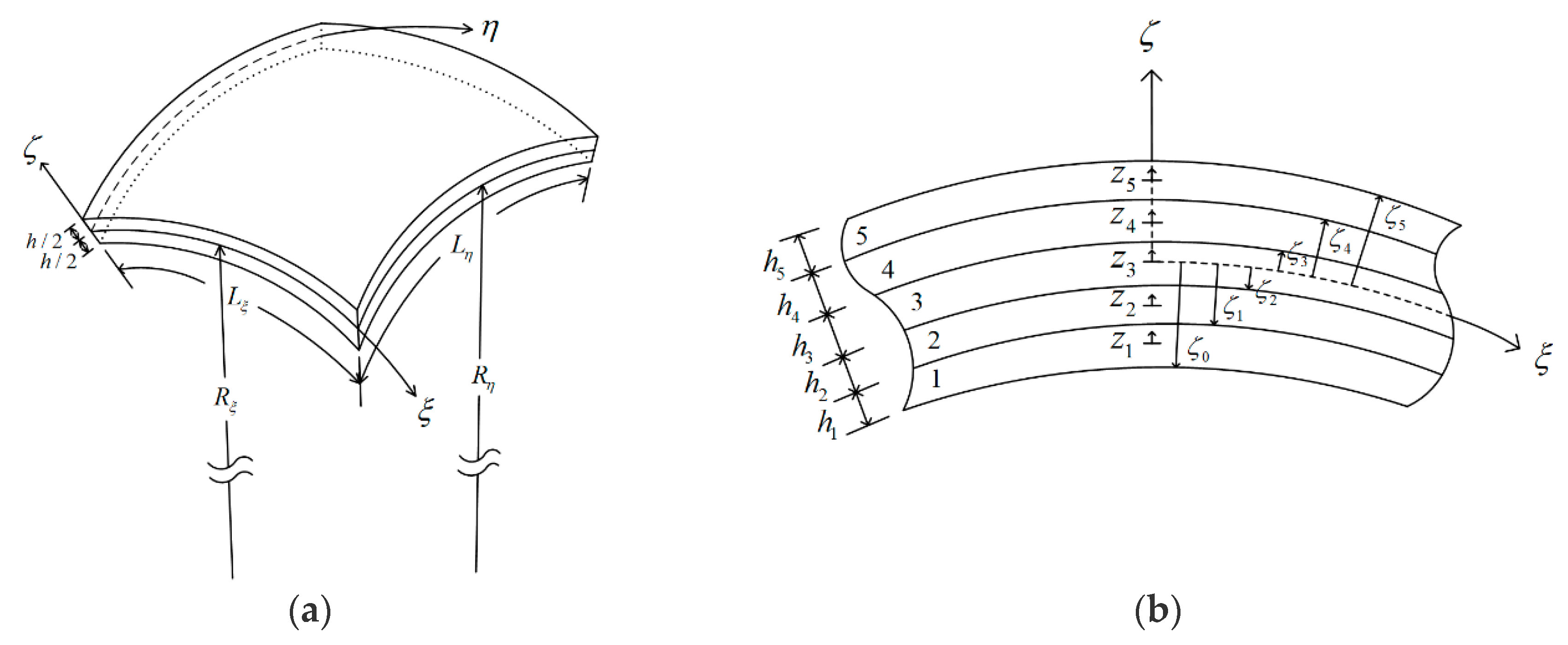
In this work, we consider a simply supported, FGDC shell subjected to steady-state thermal loads, as shown in Figure 1a, in which the material properties of the shell are thickness-dependent. In the formulation, the shell is artificially divided into Nl layers with a small thickness for each individual layer, as compared with the in-surface dimensions. In order to derive the formulation, a global doubly curved coordinate system (i.e., and coordinates) is located on the mid-surface of the shell, and a set of local thickness coordinates is located at the mid-surface of each individual layer, as shown in Figure 1b, in which Nl is taken to be five. The in-surface dimensions of the shell in the directions are defined as , respectively, and the curvature radii of the shell are . The thicknesses of each individual layer and the shell are and h, respectively, while . The relationship between the global and local thickness coordinates in the mth-layer is , in which , as well as denote the global thickness coordinates measured from the mid-surface of the shell to the top and bottom surfaces of the mth-layer, respectively.
The material properties of the FGDC shell are assumed to obey a specific function distribution according to the volume fractions of the constituents through the thickness coordinate, such as the power–law distribution. The effective bulk modulus, shear modulus, thermal expansion coefficient and thermal conductivity coefficient of the FGDC shell are estimated using the Mori–Tanaka scheme, and are given as follows [23,33]:
where , and the subscripts c and m are defined as the material properties of certain ceramic and metal materials, respectively. and are the bulk modulus, shear modulus, thermal expansion coefficient, and thermal conductivity coefficient of the ceramic and metal materials, respectively. The relationships between the bulk and shear moduli, as well as Young’s modulus (E) and Poisson’s ratio (), are and .
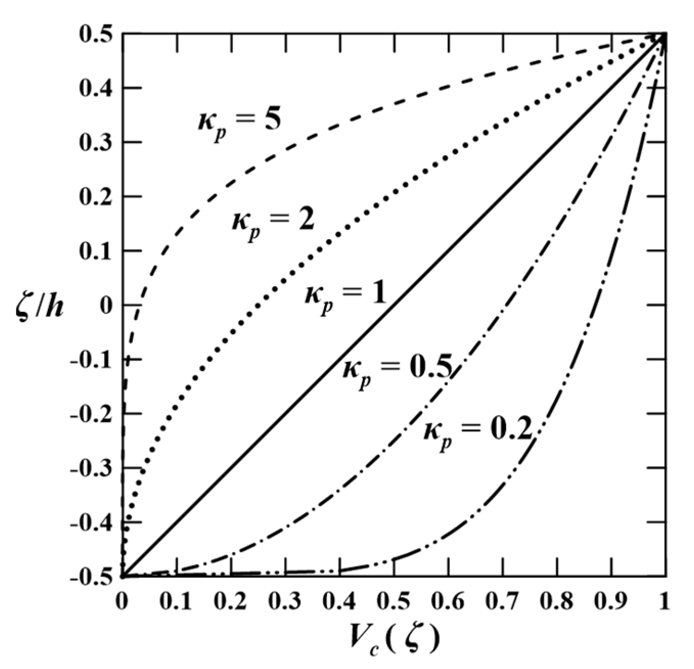
As mentioned above, the FGDC shell is considered to be a two-phase composite one, which is composed of the ceramic and metal materials according to a specific function distribution of volume fractions of the constituents through the thickness direction of the shell, such as the power–law. In the power–law model the through-thickness distribution of the volume fraction of the ceramic material, in Equations (1)–(4), is given by
where , when , such that , , , and ; as well as , when , such that , , , and . denotes the material–property gradient index for the power–law model. The distributions of the volume fraction along with the thickness direction of the shell are shown in Figure 2, in which the values of κp is taken to be κp = 0.2, 0.5, 1, 2, and 5.
3. Heat Conduction Analysis
A heat conduction analysis of the FGDC shell subjected to a steady-state thermal load will first be analyzed, and the determined temperature distribution of the shell domain is then used for the thermomechanical analysis of the shell. The material properties of the FGDC shell are considered to be dependent upon the thickness coordinate and temperature.
The equation of steady-state heat conduction of the shell without heat generation is given as
where the commas denote partial differentiation with respect to the suffix variables, denote the heat fluxes in the directions, and . are the scale factors in the directions, respectively, in which and .
The relations between the heat flux and temperature change in the directions are given as
where T denotes the temperature change, which is measured from the room temperature (), and = 300 K. In addition, the current temperature variable is defined as , such that .
The state space equations related to the heat conduction analysis of the FGDC shell is given as
The temperature changes on the top and bottom surfaces of the FGDC shell are given as
where and are the applied temperature changes at the bottom and top surfaces of the DC shell.
In this work, the temperature change prescribed on the top and bottom surfaces of the DC shell are expanded as the double Fourier series as , in which and , as well as are the half-wave numbers, the values of which are positive integers. In addition, the thermal conditions at the edges are = 300 K (or T = 0 K).
For the fully simply supported boundary conditions, the thermal field variables can also be expressed as the double Fourier series in the in-surface domain to exactly satisfy the edge conditions, as follows:
where the symbols of double summations will be omitted in the later work of this paper for brevity.
Substituting Equations (13) and (14) in (10), the authors can obtain
Equation (15) represents two simultaneously first-order differential equations in terms of two variables (i.e., ), while the related coefficients are dependent on the temperature variable and thickness coordinate. A modified Pagano method with an iteration process is thus used to obtain the through-thickness distributions of the temperature changes. The relevant solution process of the modified Pagano method can be found in Wu and Lu [56], and is not repeated here for brevity.
4. Coupled Thermoelastic Analysis
In the former Section, a heat conduction analysis of the FGDC shell under thermal loads is presented. Once the through-thickness distribution of the temperature changes of the DC shell is obtained, an FDCL method can be developed for the thermal deformation and stress analyses of the FGDC shell, and the corresponding formulation is derived as follows.
4.1. Kinematic and Kinetic Assumptions
In an earlier work, Wu and Li [52,54,55] developed an RMVT-based FDCL for the elastic deformation, stress, free vibration, and buckling analyses of simply supported, laminated composite plates and shells. The earlier formulation is then extended to the elastic deformation and stress analyses of simply supported, FGDC shell, in which the primary variables of a typical layer (i.e., the mth-layer) of the shell, of which the domains are in and , and , are thus given by
where , in which denote the elastic displacement components at the ith-nodal surface of the mth-layer of the shell, while , , and are the transverse shear and normal stress components. (i = 1, 2,…, and (n + 1)) is the shape function of the corresponding ith-nodal surface. n denotes the related orders used for expansions of each primary variable, and when n = 1, 2, and 3, the FDCL methods are called linear, quadratic, and cubic ones, respectively.
For a typical layer, the linear constitutive equations, which are valid for the orthotropic materials, are given by
where are the stress components; are the strain components; (i, j = 1–6) are the elastic coefficients, which are variable through the thickness direction of each FGEM individual layer, and are constants in the homogeneous one. (i = 1–3) denote the stress-temperature coefficients, and (i = 1–3), in which (i = 1–3) are the thermal expansion coefficients in the directions.
The strain–displacement relations for each individual layer are written as follows:
where the commas denote partial differentiation with respect to the suffix variables, and .
4.2. An RMVT-Based Weak-form Formulation
The Reissner mixed variational theorem is used to derive the system equations of the FGDC shell for the FDCL methods, and its corresponding energy functional is written in the form of
where denotes the DC shell domain on the surface, and denotes the top surface () and the bottom one () of the shell, in which denote the portions of the edge boundary, in which the surface traction and elastic displacement components are prescribed, respectively (i.e., and , in which i = , , and ); is the complementary energy density function.
In this formulation, we artificially divide the shell into a series of Nl finite layers and take the elastic displacement components and transverse shear and normal stress components as the primary variables subject to variation. A weak-form formulation can be derived by expressing the energy functional in terms of the primary variables, and then letting the first-order variation of the Reissner energy functional be zero, which yields
where the superscript of T denotes the transposition of the matrices or vectors; and and stand for the boundary edges, in which the essential and natural conditions are prescribed. In addition,
where i = 1, 2, …, (n + 1), (k, l = 1 and 2), , (l = 1 and 2).
4.3. System Equations and Boundary Conditions
The thermoelastic static behavior of a simply supported, FGDC shell under thermal loads is studied in the following illustrative examples, in which the temperature-independent material properties are used. The applied thermal conditions on the top and bottom surfaces of the shell are mentioned in Equations (13) and (14), and the traction free conditions are given as follows:
As mentioned before, the thermal conditions at the edges are = 300 K (or T = 0 K). In addition, the edge boundary conditions of each individual layer are considered as fully simple supports, which requires that the following quantities are satisfied.
where .
The primary variables of each individual layer are expanded as the double Fourier series as follows:
where the edge boundary conditions of the FGDC shell are exactly satisfied.
Substituting Equations (39)–(41) in (25) and then imposing the stationary principle of the Reissner energy functional (i.e., ), we finally obtain the system equations of the FGDC shell, as follows:
According to the above weak-form formulation, the authors can analyze the thermoelastic static behavior of simply supported, FGDC shells when the thermal loads are applied, which means the primary variables at each nodal surface can be determined, and subsequently the in-surface stress components at the nodal surfaces can be obtained using the resulting primary variables.
5. Illustrative Examples
In the following numerical examples the orders for expansions of the field variables in the RMVT-based FDCL methods are defined to be identical to one another, which means the in- and out-of-surface elastic displacements, and the transverse shear and normal stresses, are expanded as the nth-order Lagrange polynomials in the thickness coordinate of each layer, and n is taken to be 1, 2, and 3 for the linear, quadrature, and cubic FLDC methods, respectively.
5.1. Sandwiched Composite Spherical Shells
The thermoelastic behavior of simply supported, sandwiched composite spherical shells under the thermal loads has been investigated by Brischetto and Carrera [20] using various advanced and refined shell theories deduced from the CUF, while Khare et al. [57] used the FSDT and HSDT, in which the face sheets are made of the graphite-epoxy composite material, and the core is made of an orthotropic elastic material. The through-thickness distribution of the temperature change was directly given as , and . These solutions are thus used to validate the accuracy and convergence rate of assorted RMVT-based FDCL methods. The lay-up of the sandwiched spherical shell is [0°/core/0°]. The material properties of face sheets are given as , , , , , , and , and those of the core are , , , , , , and . The material properties in this example are assumed to be temperature-independent.
The geometric parameters of the shell are , , and A set of dimensionless variables is defined as follows:
where and
Table 1 shows the linear-, quadratic-, and cubic-order solutions of the RMVT-based FDCL methods for the out-of-surface displacement components induced at certain positions of the thick sandwiched spherical shell, in which and denote the number of divided layers of face sheets and core, respectively, such that . It can be seen in Table 1 that various RMVT-based FDCL methods converge rapidly, and the convergent solutions are obtained when are taken as , (2, 8), and (1, 2) for linear, quadratic, and cubic FDCL methods, respectively, on the basis of the same four digits after the decimal point. The performance of these FDCL methods is the cubic FDCL method > quadrature FDCL method > linear FDCL method, in which the symbol “>” means a more accurate result and a faster convergence rate. These convergent solutions are also compared with those obtained using the CLT [20], FSDT [20,57], HSDT [57], ESLTs with first-, second-, third-, and fourth-orders (i.e., ED1, ED2, ED3, and ED4) [20], various ESLTs combined with Murakami’s zig-zag function [58] (i.e., EDZ1, EDZ2, and EDZ3) [20] and layer-wise linear, quadratic, cubic, and quartic theories (i.e., LD1, LD2, LD3, and LD4) [20]. The results show the convergent solutions of FDCL methods are in excellent agreement with the closed-form solutions of layer-wise cubic and quartic theories, and the accuracy of the advanced and refined theories is LD theories > EDZ theories > ED theories when the orders used to expand the field variables through the thickness direction remain the same, in which the symbol “>” means more accurate. In addition, the out-of-surface displacement decreases when the curvature radius of the sandwiched spherical shell becomes smaller, which also means when the shell becomes a deeper shell.
Figure 3 shows the through-thickness distributions of displacement and stress components induced in the sandwiched spherical shells, in which , , , and (thick shell), 10 (moderately thick shell), and 20 (thin shell). In the case of homogeneous sandwiched spherical shells, the through-thickness distributions of out-of-surface and in-surface displacements appear to be global linear and layer-wise linear functions, respectively, while those of in-surface and out-of-surface stress components are layer-wise linear and layer-wise higher-order polynomial functions. The in-surface stresses are discontinuous when crossing over the interfaces between adjacent layers, because the material properties are dissimilar to each other for the bottom surface of the upper layer and the top surface of the lower layer, which might result in a matrix cracking failure at the face sheet-core interfaces. In addition, the transverse shear and normal stresses are shown to be concentrated at the face sheet-core interfaces, which might cause delamination damage.
5.2. FG Cylindrical Shells
The thermoelastic behavior of a simply supported, FG cylindrical shell under a thermal load has been investigated by Cinefra et al. [25] using various layer-wise theories and a quasi-3D theory deduced from the CUF, in which the through-thickness distribution of the temperature change of the shell was obtained by performing a heat conduction analysis of it. The specified temperature changes on the top and bottom surfaces are given as and , respectively, in which . The FG cylindrical shell was made of a two-phase composite material, with the particulate-phase material being ceramic zirconia (ZrO2) and the matrix-phase material being nickel-based alloy (Monel, 70Ni-30Cu). The volume fractions of the ceramic and metal materials (i.e., and ) are taken to be and , in which the subscripts m and c denote the metal and ceramic materials, respectively, while the effective material properties are estimated using the Mori–Tanaka micromechanics scheme [33]. The material properties of these two phase materials [23,32] are given as , , , , and , , , . The material properties in this example are assumed to be temperature-independent. The geometric parameters of the shell are , , , , and .
The dimensionless variables are defined as follows:
where and .
Table 2 shows the results of cubic FDCL methods for various field variables induced in the shell, in which . The convergent solutions are obtained when the number of divided layers is taken to be 40, and the relative errors of various field variables are below 0.9% as compared with the 400-layer solutions. The convergence rate of various field variables in the case of the shell with is slightly slower than that in the case of case of the shell with . These convergent solutions are also shown to be in excellent agreement with the solutions of the LD14 method [25] and the quasi-3D theory [25].
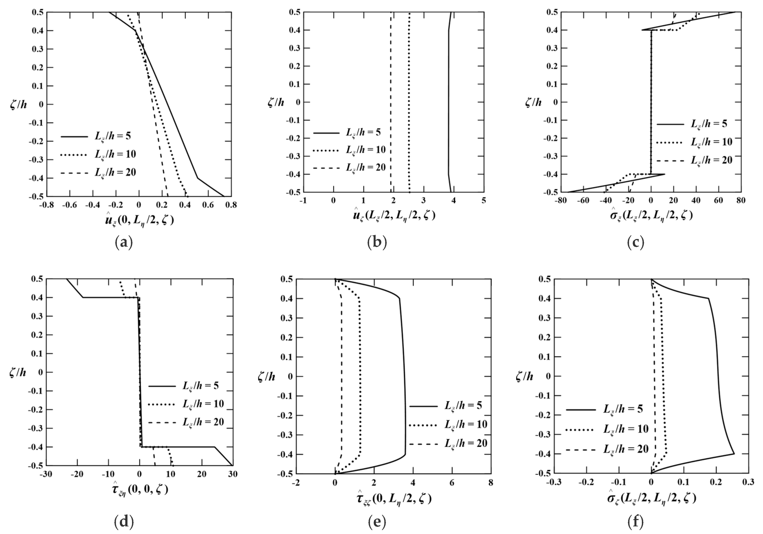
Figure 4 shows the through-thickness distributions of assorted field variables induced in the single-layered FG cylindrical shell, in which , and . It can be seen in Figure 4a that the distributions of the temperature change of the FG cylindrical shell appear to be higher-order polynomial functions through the thickness direction, rather than the linear function in the case of homogeneous sandwiched shell. The results in Figure 4b–f also show the through-thickness distributions of thermal deformations and thermal stresses are higher-order polynomial functions, and the trend of the distributions of transverse shear and normal stresses is much steeper than that of the distributions of thermal deformations and in-surface stresses.
5.3. FGDC Shells
In the previous two Sections, the FDCL methods with linear-, quadratic-, and cubic-orders are validated by comparing their solutions with the quasi-3D and accurate 2D solutions available in the literature, in which the material properties of the shells are considered to remain at room temperature (). In this section, the authors investigate the thermoelastic behavior of simply supported, FGDC shells. The DC shell is made of the two-phase composite material, in which the particulate-phase material is ceramic zirconia and the matrix-phase material is metal Ti-6Al-4V, the TD material properties of which are given in the form of
where P denotes various material properties, such as E, , , and , as well as the values of coefficients are listed in Table 3 [34].
The surface thermal conditions of the shell and dimensionless variables are the same as those used in the previous Section, i.e., Equations (39)–(41). The thermal conditions of the top and bottom surfaces of the shell are and , respectively, in which and , and the cubic FDCL method is used.
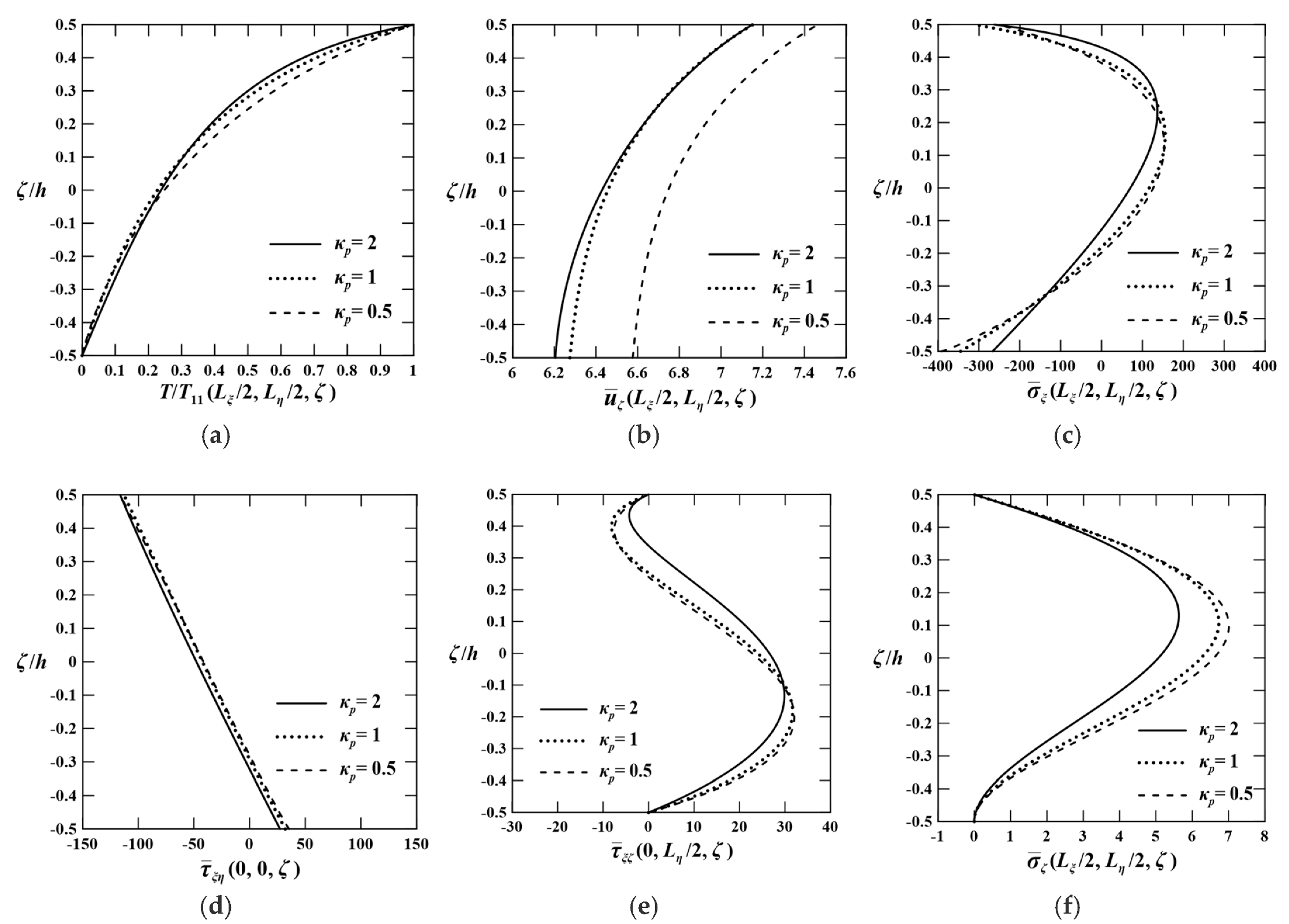
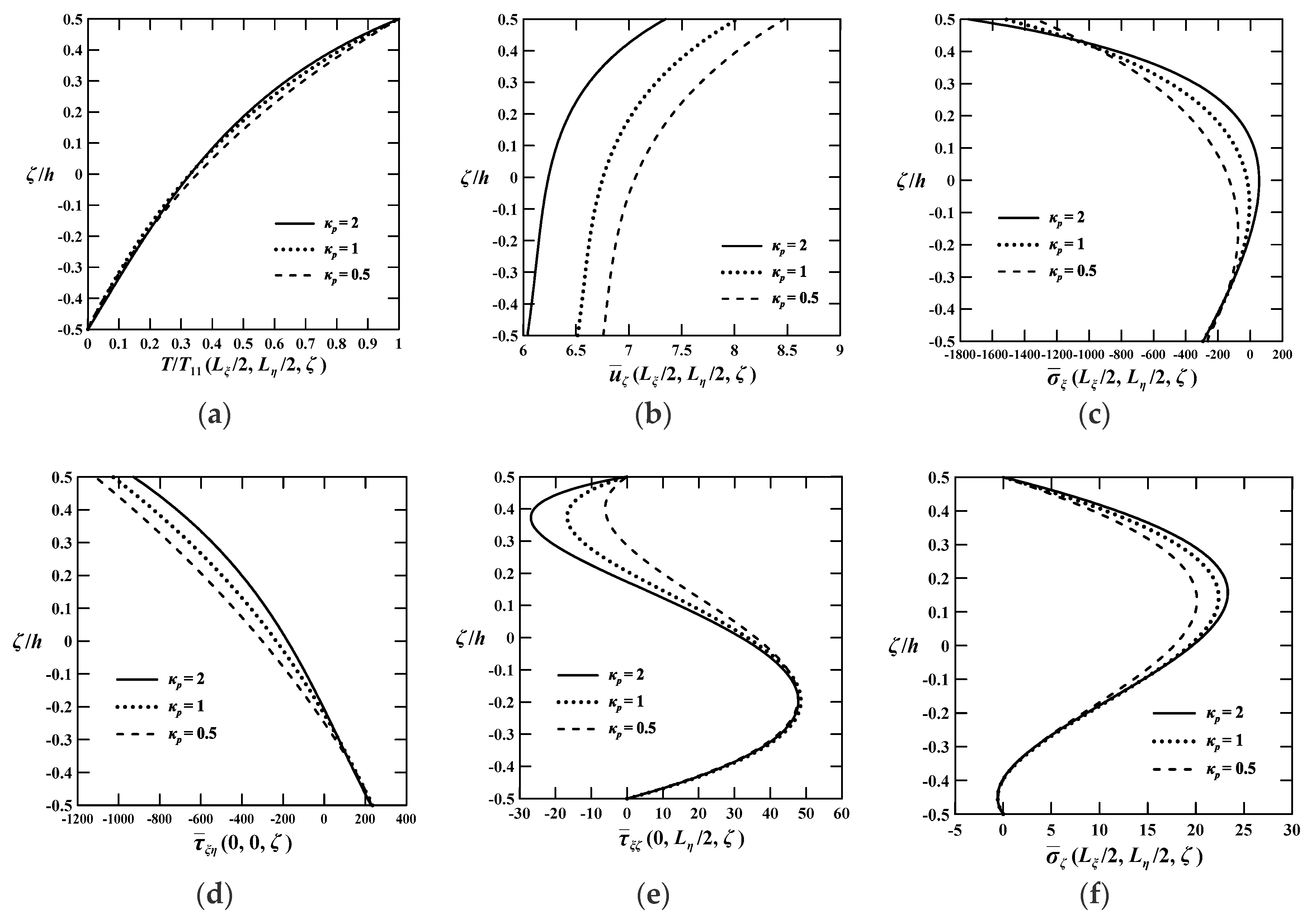
Figure 5 shows the through-thickness distributions of assorted field variables induced in the FGDC shell, in which the geometric parameters of the shell are , and , in which the power–law model is used and the values of . It can be seen in Figure 5 that various displacement and stress components induced in the FGDC shell appear to be higher-order polynomial functions, which obviously differs from those distributions assumed in CST and FSDT.
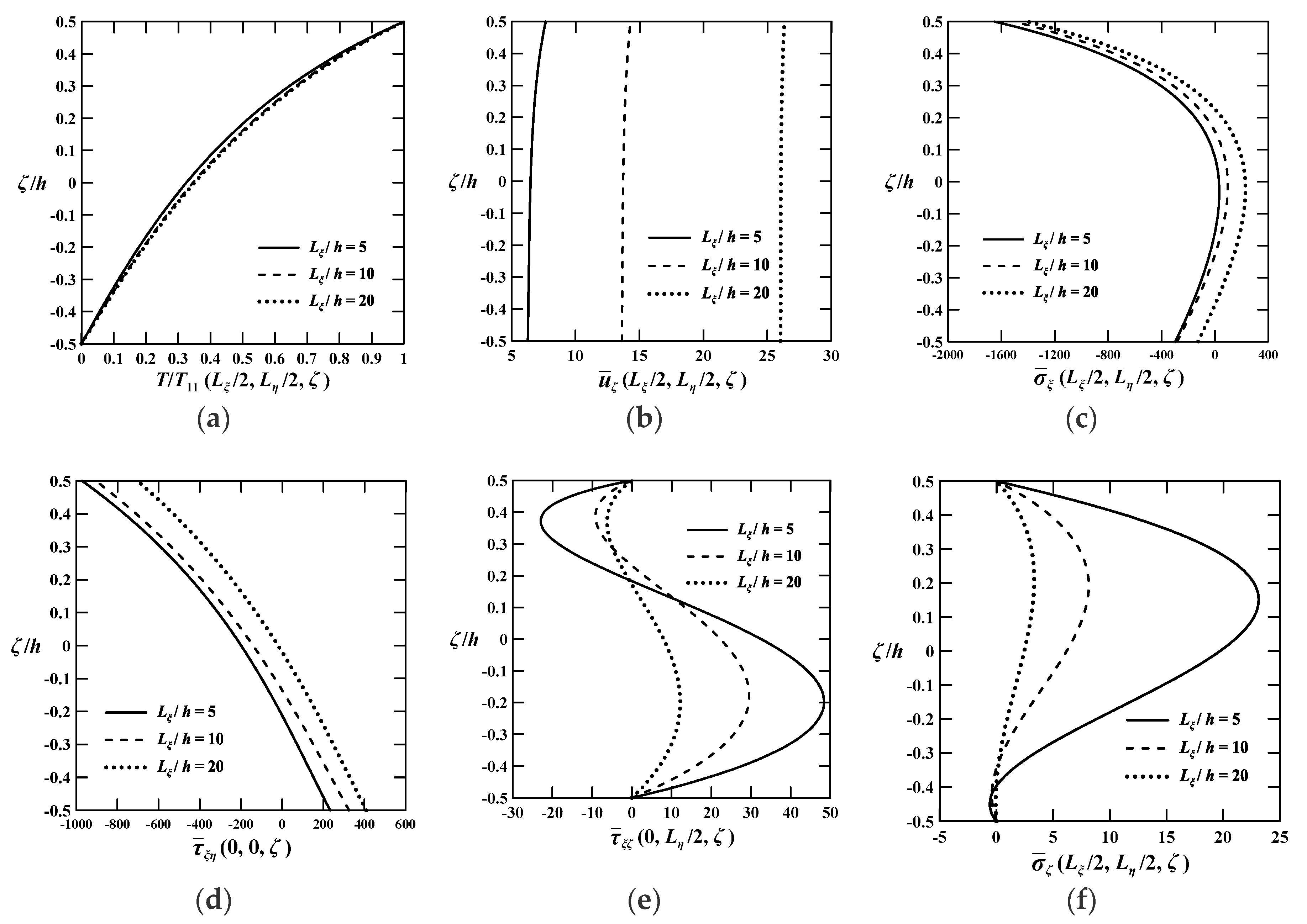
Figure 6 shows the through-thickness distributions of thermal and elastic field variables induced in the FGDC shells, in which , , and , which are the thick, moderately thick, and thin shells, respectively. It can be seen in Figure 6 that the effects of length-to-thickness ratio on the thermal field variables are minor, while those on the elastic field variables are significant, especially on the elastic deformation, transverse shear stress, and transverse normal stress components. The magnitude order of the various elastic field variables is in-surface stress components () > transverse shear stress component () > transverse normal stress component (). It is clear that the transverse shear and normal stress components increase when the shell becomes thicker. The effects of the transverse shear and normal stresses must thus be taken into account in the thermoelastic analysis of the FGDC shell when it becomes thicker.
6. Concluding Remarks
In this work, the authors develop a unified formulation of RMVT-based FDCL methods with various orders to investigate the thermoelastic behavior of simply supported, laminated composite and FGDC shells, and subjected to thermal loads. Implementation of assorted RMVT-based FDCL methods shows the current FDCL methods converge rapidly, and their convergent solutions are in excellent agreement with the quasi-3D and accurate 2D solutions available in the literature. The through-thickness distributions of thermal and elastic field variables induced in the laminated composite shells appear to be layer-wise linear functions for the displacement and in-surface stress components, while they are higher-order polynomial functions for the transverse shear and stress components. In contrast, the through-thickness distributions of thermal and elastic field variables induced in the FGDC shells appear to be higher-order polynomial functions for all field variables. The results reveal the above-mentioned through-thickness distributions of field variables induced in FGDC shells are inconsistent with the kinematic assumptions of the existing 2D equivalent single-layered shell theories, and development of a specific advanced 2D shell theory for the FG shells is thus needed. Because the current cubic FDCL methods are demonstrated to be superior to the quadrature and linear ones, the layerwise third-order deformation theory may be a potential candidate for the future study of FGDC shells.
Author Contributions
Conceptualization, C.-P.W.; methodology, C.-P.W.; software, Y.-W.H.; validation, C.-P.W., Y.-W.H.; formal analysis, C.-P.W., Y.-W.H.; investigation, C.-P.W., Y.-W.H.; resources, C.-P.W.; data curation, Y.-W.H.; writing—original draft preparation, C.-P.W.; writing—review and editing, C.-P.W.; visualization, C.-P.W.; supervision, C.-P.W.; project administration, C.-P.W.; funding acquisition, C.-P.W.
Funding
This research was funded by Ministry of Science and Technology, Taiwan, grant number MOST 103-2221-E-006-064-MY3.
Conflicts of Interest
The authors declare no conflict of interest.
References
- Koizumi, M. FGM activities in Japan. Compos. Part B 1997, 28, 1–4. [Google Scholar] [CrossRef]
- Koizumi, M. Recent progress of functionally graded materials in Japan. Ceram. Eng. Sci. Proc. 1992, 13, 333–347. [Google Scholar]
- Shaw, L.L. Thermal residual stresses in plates and coating composed of multi-layered and functionally graded materials. Compos. Part B 1998, 29, 199–210. [Google Scholar] [CrossRef]
- Hill, R. A self-consistent mechanics of composite materials. J. Mech. Phys. Solids 1965, 13, 213–222. [Google Scholar] [CrossRef]
- Chi, S.H.; Chung, Y.L. Mechanical behavior of functionally graded material plates under transverse load-Part I: Analysis. Int. J. Solids Struct. 2006, 43, 3657–3674. [Google Scholar] [CrossRef]
- Chung, Y.L.; Chang, H.X. Mechanical behavior of rectangular plates with functionally graded coefficient of thermal expansion subjected to thermal loading. J. Therm. Stresses 2008, 31, 368–388. [Google Scholar] [CrossRef]
- Dai, H.L.; Dai, T. Analysis of the thermoelastic bending of a functionally graded material cylindrical shell. Meccanica 2014, 49, 1069–1081. [Google Scholar] [CrossRef]
- Zenkour, A.M.; Alghamdi, N.A. Bending analysis of functionally graded sandwich plates under the effect of mechanical and thermal loads. Mech. Adv. Mater. Struct. 2010, 17, 419–432. [Google Scholar] [CrossRef]
- Zenkour, A.M.; Alghamdi, N.A. Thermoelastic bending analysis of functionally graded sandwich plates. J. Mater. Sci. 2008, 43, 2574–2589. [Google Scholar] [CrossRef]
- Kreja, I. Equivalent single-layer models in deformation analysis of laminated multilayered plates. Acta Mech. 2019, 230, 2827–2851. [Google Scholar] [CrossRef] [Green Version]
- Grigolyuk, E.I.; Kulikov, G.M. Numerical solution of problems involving the statics of geometrically nonlinear anisotropic multilayer shells of revolution. Mech. Compos. Mater. 1981, 17, 294–302. [Google Scholar] [CrossRef]
- Grigolyuk, E.I.; Kulikov, G.M. Theory and numerical solution of problems of the statics of multilayered reinforced shells. Mech. Compos. Mater. 1987, 22, 450–457. [Google Scholar] [CrossRef]
- Washizu, K. Variational Methods in Elasticity and Plasticity; Pergamon Press: New York, NY, USA, 1982. [Google Scholar]
- Grigolyuk, E.I.; Kulikov, G.M. Generalized model of the mechanics of thin-walled structures made of composite materials. Mech. Compos. Mater. 1989, 24, 537–543. [Google Scholar] [CrossRef]
- Carrera, E. Theories and finite elements for multilayered plates and shells: A unified compact formulation with numerical assessments and benchmarking. Arch. Comput. Methods Eng. 2003, 10, 215–296. [Google Scholar] [CrossRef]
- Carrera, E.; Boscolo, C.M.; Robaldo, A. Hierarchic multilayered plate elements for coupled multifield problems of piezoelectric adaptive structures: Formulation and numerical assessment. Arch. Comput. Methods Eng. 2007, 14, 383–430. [Google Scholar] [CrossRef]
- Carrera, E. An assessment of mixed and classical theories for the thermal stress analysis of orthotropic multilayered plates. J. Therm. Stresses 2000, 23, 797–831. [Google Scholar] [CrossRef]
- Carrera, E.; Brischetto, S.; Robaldo, A. Variable kinematic model for the analysis of functionally graded materials plates. AIAA J. 2008, 46, 194–203. [Google Scholar] [CrossRef]
- Brischetto, S.; Carrera, E. Coupled thermo mechanical analysis of one-layered and multilayered plates. Compos. Struct. 2010, 92, 1793–1812. [Google Scholar] [CrossRef]
- Brischetto, S.; Carrera, E. Thermal stress analysis by refined multilayered composite shell theories. J. Therm. Stresses 2009, 32, 165–186. [Google Scholar] [CrossRef]
- Carrera, E. Historical review of zig-zag theories for multilayered plates and shells. Appl. Mech. Rev. 2003, 56, 287–308. [Google Scholar] [CrossRef]
- Brischetto, S.; Leetsch, R.; Carrera, E.; Wallmersperger, T.; Kröplin, B. Thermo mechanical bending of functionally graded plates. J. Therm. Stresses 2008, 31, 286–308. [Google Scholar] [CrossRef]
- Carrera, E. An assessment of mixed and classical theories on global and local response of multilayered orthotropic plates. Compos. Struct. 2000, 50, 183–198. [Google Scholar] [CrossRef]
- Carrera, E.; Cinefra, M.; Fazzolari, F.A. Some results on thermal stress of layered plates and shells by using unified formulation. J. Therm. Stresses 2013, 36, 589–625. [Google Scholar] [CrossRef]
- Cinefra, M.; Carrera, E.; Brischetto, S.; Belouettar, S. Thermo mechanical analysis of functionally graded shells. J. Therm. Stresses 2010, 33, 942–963. [Google Scholar] [CrossRef]
- Cinefra, M.; Petrolo, M.; Li, G.; Carrera, E. Variable kinematic shell elements for composite laminates accounting for hygrothermal effects. J. Therm. Stresses 2017, 40, 1523–1544. [Google Scholar] [CrossRef] [Green Version]
- Cinefra, M.; Valvano, S.; Carrera, E. Thermal stress analysis of laminated structures by a variable kinematic MICC9 shell element. J. Therm. Stresses 2016, 39, 121–141. [Google Scholar] [CrossRef]
- Carrera, E.; Cinefra, M.; Zappino, E.; Petrolo, M. Finite Element Analysis of Structures through Unified Formulation; John Wiley & Sons Ltd.: Chichester, UK, 2014. [Google Scholar]
- Fazzolari, F.A. Reissner’s mixed variational theorem and variable kinematics in the modeling of laminated composite and FGM doubly curved shells. Compos. Part B Eng. 2016, 89, 408–423. [Google Scholar] [CrossRef]
- Fazzolari, F.A.; Carrera, E. Coupled thermoelastic effect in free vibration analysis of anisotropic multilayered plates and FGM plates by using a variable-kinematics Ritz formulation. Eur. J. Mech. A/Solids 2014, 44, 157–174. [Google Scholar] [CrossRef]
- Fazzolari, F.A. Model characteristics of P- and S-FGM plates with temperature-dependent materials in thermal environment. J. Therm. Stresses 2016, 39, 854–873. [Google Scholar] [CrossRef]
- Reddy, J.N.; Cheng, Z.Q. Three-dimensional thermomechanical deformations of functionally graded rectangular plates. Eur. J. Mech. A/Solids 2001, 20, 841–855. [Google Scholar] [CrossRef]
- Mori, T.; Tanaka, K. Average stress in matrix and average elastic energy of materials with misfitting inclusions. Acta Metall. 1973, 21, 571–574. [Google Scholar] [CrossRef]
- Reddy, J.N.; Chin, C.D. Thermomechanical analysis of functionally graded cylinders and plates. J. Therm. Stresses 1998, 21, 593–626. [Google Scholar] [CrossRef]
- Jabbari, M.; Sohrabpour, S.; Eslami, M.R. Mechanical and thermal stresses in functionally graded hollow cylinder due to radially symmetric loads. Int. J. Press. Vessel Pip. 2002, 79, 493–497. [Google Scholar] [CrossRef]
- Jabbari, M.; Sohrabpour, S.; Eslami, M.R. General solution for mechanical and thermal stresses in a functionally graded hollow cylinder due to nonaxisymmetric steady-state loads. J. Appl. Mech. 2003, 70, 111–118. [Google Scholar] [CrossRef]
- Poultangari, R.; Jabbari, M.; Eslami, M.R. Functionally graded hollow spheres under non-axisymmetric thermo mechanical loads. Int. J. Pressure Vessel Pip. 2008, 85, 295–305. [Google Scholar] [CrossRef]
- Kulikov, G.M.; Plotnikova, S.V. 3D exact thermoelastic analysis of laminated composite shells via sampling surfaces method. Compos. Struct. 2014, 115, 120–130. [Google Scholar] [CrossRef]
- Kulikov, G.M.; Plotnikova, S.V. Three-dimensional thermal stress analysis of laminated composite plates with general layups by a sampling surfaces method. Eur. J. Mech. A/Solids 2015, 49, 214–226. [Google Scholar] [CrossRef]
- Kulikov, G.M.; Plotnikova, S.V. A sampling surfaces method and its implementation for 3D thermal stress analysis of functionally graded plates. Compos. Struct. 2015, 120, 315–325. [Google Scholar] [CrossRef]
- Akbari Alashti, R.A.; Khorsand, M. Three-dimensional nonlinear thermoelastic analysis of functionally graded cylindrical shells with piezoelectric layers by differential quadrature method. Acta Mech. 2012, 223, 2565–2590. [Google Scholar] [CrossRef]
- Arefi, M. Nonlinear thermoelastic analysis of thick-walled functionally graded piezoelectric cylinder. Acta Mech. 2013, 224, 2771–2783. [Google Scholar] [CrossRef]
- Adineh, M.; Kadkhodayan, M. Three-dimensional thermoelastic analysis of multi-directional functionally graded rectangular plates on elastic foundation. Acta Mech. 2017, 228, 881–899. [Google Scholar] [CrossRef]
- Wu, C.P.; Chiu, K.H.; Wang, Y.M. A review on the three-dimensional analytical approaches of multilayered and functionally graded piezoelectric plates and shells. CMC Comput. Mater. Contin. 2008, 8, 93–132. [Google Scholar]
- Wu, C.P.; Liu, Y.C. A review of semi-analytical numerical methods for laminated composite and multilayered functionally graded elastic/piezoelectric plates and shells. Compos. Struct. 2006, 147, 1–15. [Google Scholar] [CrossRef]
- Reddy, J.N. A simple higher-order theory for laminated composite plates. J. Appl. Mech. 1984, 51, 745–752. [Google Scholar] [CrossRef]
- Shen, H.S. Nonlinear bending response of functionally graded plates subjected to transverse loads and in thermal environments. Int. J. Mech. Sci. 2002, 44, 561–584. [Google Scholar] [CrossRef]
- Shen, H.S. Nonlinear thermal bending response of FGM plates due to heat conduction. Compos. Part B 2007, 38, 201–215. [Google Scholar] [CrossRef]
- Shen, H.S.; Wang, H. Nonlinear bending of FGM cylindrical panels resting on elastic foundations in thermal environments. Eur. J. Mech. A/Solids 2015, 49, 49–59. [Google Scholar] [CrossRef]
- Mahapatra, T.R.; Kar, V.R.; Panda, S.K.; Mehar, K. Nonlinear thermoelastic deflection of temperature-dependent FGM curved shallow shell under nonlinear thermal loading. J. Therm. Stresses 2017, 40, 1184–1199. [Google Scholar] [CrossRef]
- Wu, C.P.; Ding, S. Coupled thermo electro-mechanical analysis of sandwiched hybrid functionally graded elastic material and piezoelectric plates under thermal loads. Proc. Inst. Mech. Eng. Part C J. Mech. Eng. Sci. 2018, 232, 1851–1870. [Google Scholar] [CrossRef]
- Wu, C.P.; Li, H.Y. The RMVT- and PVD-based finite layer methods for the three-dimensional analysis of multilayered composite and FGM plates. Compos. Struct. 2010, 92, 2476–2496. [Google Scholar] [CrossRef]
- Wu, C.P.; Chang, Y.T. A unified formulation of RMVT-based finite cylindrical layer methods for sandwich circular hollow cylinders with an embedded FGM layer. Compos. Part B 2012, 43, 3318–3333. [Google Scholar] [CrossRef]
- Wu, C.P.; Li, H.Y. An RMVT-based finite rectangular prism method for the 3D analysis of sandwich FGM plates with various boundary conditions. CMC Comput. Mater. Contin. 2013, 34, 27–62. [Google Scholar]
- Wu, C.P.; Li, H.Y. RMVT-based finite cylindrical prism methods for multilayered functionally graded circular hollow cylinders with various boundary conditions. Compos. Struct. 2013, 100, 592–608. [Google Scholar] [CrossRef]
- Wu, C.P.; Lu, Y.C. A modified Pagano method for the 3D dynamic responses of functionally graded magneto-electro-elastic plates. Compos. Struct. 2009, 90, 363–372. [Google Scholar] [CrossRef]
- Khare, R.K.; Kant, T.; Garg, A.K. Closed-form thermo mechanical solutions of higher-order theories of cross-ply laminated shallow shells. Compos. Struct. 2003, 59, 313–340. [Google Scholar] [CrossRef]
- Murakami, H. Laminated composite plates theory with improved in-plane response. J. Appl. Mech. 1986, 53, 661–666. [Google Scholar] [CrossRef]
Figure 1.
(a) The configuration of a FGDC shell; (b) the global and local coordinates of the DC shell.
Figure 1.
(a) The configuration of a FGDC shell; (b) the global and local coordinates of the DC shell.

Figure 2.
Through-thickness distributions of the volume fraction of the FGDC shell for different values of material–property gradient indices of the power–law model.
Figure 2.
Through-thickness distributions of the volume fraction of the FGDC shell for different values of material–property gradient indices of the power–law model.

Figure 3.
Through-thickness distributions of thermal and elastic field variables induced in a [0°/core/0°] laminated spherical shell with different values of (). (a) In-surface displacements; (b) Out-of-surface displacement; (c) In-surface normal stress; (d) In-surface shear stress; (e) Transverse shear stress; (f) Transverse normal stress.

Figure 4.
Through-thickness distributions of thermal and elastic field variables induced in an FG cylindrical shell with different values of . (a) Temperature; (b) Out-of-surface displacement; (c) In-surface normal stress; (d) In-surface shear stress; (e) Transverse shear stress; (f) Transverse normal stress.

Figure 5.
Through-thickness distributions of thermal and elastic field variables induced in an FGDC shell with different values of . (a) Temperature; (b) Out-of-surface displacement; (c) In-surface normal stress; (d) In-surface shear stress; (e) Transverse shear stress; (f) Transverse normal stress.

Figure 6.
Through-thickness distributions of thermal and elastic field variables induced in an FGDC shell with different values of (). (a) Temperature; (b) Out-of-surface displacement; (c) In-surface normal stress; (d) In-surface shear stress; (e) Transverse shear stress; (f) Transverse normal stress.


Table 1.
Results of convergence and accuracy studies for the dimensionless deflections induced in thick sandwiched spherical shells ([0°/core/0°]) under a thermal load.
Table 1.
Results of convergence and accuracy studies for the dimensionless deflections induced in thick sandwiched spherical shells ([0°/core/0°]) under a thermal load.
| Theories | (Plates) | |||
|---|---|---|---|---|
| Linear FDCL method | ||||
| (, ) | 4.3444 | 4.3683 | 4.3744 | 4.3764 |
| (, ) | 4.3518 | 4.375 | 4.3809 | 4.3828 |
| (, ) | 4.3422 | 4.3656 | 4.3715 | 4.3734 |
| (, ) | 4.3497 | 4.3732 | 4.3791 | 4.3811 |
| (, ) | 4.3498 | 4.3733 | 4.3792 | 4.3811 |
| (, ) | 4.3496 | 4.373 | 4.3789 | 4.3809 |
| Quadratic FDCL method | ||||
| (, ) | 4.3493 | 4.3728 | 4.3787 | 4.3806 |
| (, ) | 4.3494 | 4.3728 | 4.3787 | 4.3807 |
| (, ) | 4.3495 | 4.373 | 4.3789 | 4.3808 |
| (, ) | 4.3496 | 4.373 | 4.3789 | 4.3809 |
| Cubic FDCL method | ||||
| (, ) | 4.3497 | 4.3731 | 4.379 | 4.381 |
| (, ) | 4.3496 | 4.373 | 4.3789 | 4.3809 |
| (, ) | 4.3496 | 4.373 | 4.3789 | 4.3809 |
| (, ) | 4.3496 | 4.373 | 4.3789 | 4.3809 |
| CLT [20] | 1.8043 | 1.8025 | 1.8021 | 1.8019 |
| FSDT [20] | 3.1472 | 3.1632 | 3.1672 | 3.1685 |
| FSDT [57] | 3.2618 | 3.2745 | 3.2775 | 3.2784 |
| HSDT [57] | 4.2032 | 4.2343 | 3.2422 | 4.2448 |
| ED1 [20] | 3.1466 | 3.1631 | 3.1672 | 3.1685 |
| ED2 [20] | 3.0306 | 3.0471 | 3.0512 | 3.0525 |
| ED3 [20] | 4.1867 | 4.2308 | 4.2419 | 4.2456 |
| ED4 [20] | 4.1928 | 4.236 | 4.2469 | 4.2505 |
| EDZ1 [20] | 4.3705 | 4.419 | 4.4312 | 4.4352 |
| EDZ2 [20] | 4.3228 | 4.372 | 4.3843 | 4.3885 |
| EDZ3 [20] | 4.3261 | 4.3754 | 4.3878 | 4.3919 |
| LD1 [20] | 4.3417 | 4.3653 | 4.3712 | 4.3732 |
| LD2 [20] | 4.342 | 4.3651 | 4.3709 | 4.3729 |
| LD3 [20] | 4.3427 | 4.3658 | 4.3716 | 4.3736 |
| LD4 [20] | 4.3426 | 4.3657 | 4.3715 | 4.3735 |
Table 2.
Results of cubic FDCL methods for various field variables induced in a single-layered FGDC shell under a thermal load.
Table 2.
Results of cubic FDCL methods for various field variables induced in a single-layered FGDC shell under a thermal load.
| Cubic FDCL Methods | |||||||
|---|---|---|---|---|---|---|---|
| 50 | −3.6818 | 0.5008 | 7.4042 | −1444.4 | 27.552 | 5.2791 | |
| −3.5948 | 0.4855 | 7.2241 | −1461.3 | 26.87 | 5.1512 | ||
| −3.5685 | 0.4807 | 7.1693 | −1466.5 | 26.643 | 5.0905 | ||
| −3.5614 | 0.4794 | 7.1546 | −1467.8 | 26.5804 | 5.0744 | ||
| −3.5591 | 0.4789 | 7.1498 | −1468.3 | 26.56 | 5.0692 | ||
| LD2 [25] | −4.162 | 0.9074 | 8.8684 | −1409.8 | −7.3846 | 319.18 | |
| LD8 [25] | −3.5545 | 0.488 | 7.1548 | −1470.8 | 26.664 | 7.5271 | |
| LD14 [25] | −3.5477 | 0.4837 | 7.1361 | −1470.4 | 26.459 | 5.1982 | |
| Quasi-3D [25] | −3.5466 | 0.4833 | 7.1337 | −1481.4 | 26.448 | 5.0753 | |
| 1000 | −1.8435 | −0.4301 | 45.001 | −1127.2 | −5.4085 | 0.2023 | |
| −1.8033 | −0.4214 | 44 | −1150 | −5.2768 | 0.245 | ||
| −1.7913 | −0.4188 | 43.7 | −1156.9 | −5.2373 | 0.24 | ||
| −1.7881 | −0.4181 | 43.62 | −1158.7 | −5.2268 | 0.2393 | ||
| −1.787 | −0.4179 | 43.593 | −1159.3 | −5.2233 | 0.2391 | ||
| LD2 [25] | −1.8872 | −0.3785 | 48.034 | −1098.6 | −6.6837 | 259.6 | |
| LD8 [25] | −1.7886 | −0.4176 | 43.653 | −1159.3 | −5.2415 | −1.7681 | |
| LD14 [25] | −1.7871 | −0.4178 | 43.6 | −1159.2 | −5.2262 | 0.3165 | |
| Quasi-3D [25] | −1.7868 | −0.4178 | 43.59 | −1170.2 | −5.2242 | 0.2428 |
Table 3.
Temperature-dependent material properties of metal and ceramic materials (Ti-6Al-4V and zirconia), in which , and denotes the current temperature and its unit is K.
Table 3.
Temperature-dependent material properties of metal and ceramic materials (Ti-6Al-4V and zirconia), in which , and denotes the current temperature and its unit is K.
| Materials | Properties P(T) | P0 | P−1 | P1 | P2 | P3 |
|---|---|---|---|---|---|---|
| Zirconia [34] | E (GPa) | 244.27 | 0 | −1.371 × 10⁻³ | 1.214 × 10⁻⁶ | −3.681 × 10⁻¹⁰ |
| ν | 0.2882 | 0 | 1.133 × 10⁻⁴ | 0 | 0 | |
| α (1/K) | 12.766 × 10⁻⁶ | 0 | −1.491 × 10⁻³ | 1.00 × 10⁻⁵ | −6.778 × 10⁻¹¹ | |
| λ (W/m K) | 1.7000 | 0 | 1.276 × 10⁻⁴ | 6.648 × 10⁻⁸ | 0 | |
| Ti-6Al-4V [34] | E (GPa) | 122.56 | 0 | −4.586 × 10⁻⁴ | 0 | 0 |
| ν | 0.2884 | 0 | 1.121 × 10⁻⁴ | 0 | 0 | |
| α (1/K) | 7.5788 × 10⁻⁶ | 0 | 6.638 × 10⁻⁴ | −3.147 × 10⁻⁶ | 0 | |
| λ (W/m K) | 1.0000 | 0 | 1.704 × 10⁻² | 0 | 0 |
© 2019 by the authors. Licensee MDPI, Basel, Switzerland. This article is an open access article distributed under the terms and conditions of the Creative Commons Attribution (CC BY) license (http://creativecommons.org/licenses/by/4.0/).
Share and Cite
MDPI and ACS Style
Wu, C.-P.; He, Y.-W. Thermoelastic Stress and Deformation Analyses of Functionally Graded Doubly Curved Shells. J. Compos. Sci. 2019, 3, 94. https://doi.org/10.3390/jcs3040094
AMA Style
Wu C-P, He Y-W. Thermoelastic Stress and Deformation Analyses of Functionally Graded Doubly Curved Shells. Journal of Composites Science. 2019; 3(4):94. https://doi.org/10.3390/jcs3040094
Chicago/Turabian StyleWu, Chih-Ping, and Yu-Wen He. 2019. "Thermoelastic Stress and Deformation Analyses of Functionally Graded Doubly Curved Shells" Journal of Composites Science 3, no. 4: 94. https://doi.org/10.3390/jcs3040094