Article

Poly(ethyl methacrylate) Composite Coatings Containing Halogen-Free Inorganic Additives with Flame-Retardant Properties

1
Department of Materials Science and Engineering, McMaster University, Hamilton, ON L8S 4L7, Canada
2
Department of Mechanical Engineering, McMaster University, Hamilton, ON L8S 4L7, Canada
3
Advanced Ceramics Corporation, 2536 Bristol Circle, Oakville, ON L6H 5S1, Canada
*
Author to whom correspondence should be addressed.
J. Compos. Sci. 2022, 6(4), 104; https://doi.org/10.3390/jcs6040104
Submission received: 15 February 2022 / Revised: 6 March 2022 / Accepted: 23 March 2022 / Published: 28 March 2022
(This article belongs to the Special Issue Feature Papers in Journal of Composites Science in 2022)

Abstract

:
This investigation is motivated by the need for the development of polymer coatings containing inorganic flame-retardant materials (FRMs) and the replacement of toxic halogenated FRMs. A green strategy is reported for the fabrication of poly(ethyl methacrylate) (PEMA)-FRM composite coatings using a dip-coating method. The use of water-isopropanol co-solvent allows the replacement of regular toxic solvents for PEMA. The abilities to form concentrated solutions of high-molecular-mass PEMA and to disperse FRM particles in such solutions are the main factors in the fabrication of coatings using a dip-coating technique. Huntite, halloysite, and hydrotalcite are used as advanced FRMs for the fabrication of PEMA-FRM coatings. FTIR, XRD, SEM, and TGA data are used for the analysis of the microstructure and composition of PEMA-FRM coatings. PEMA and PEMA-FRM coatings provide corrosion protection of stainless steel. The ability to form laminates with different layers using a dip-coating method facilitates the fabrication of composite coatings with enhanced properties.

1. Introduction

Flame-retardant materials (FRMs) are vital for the development of composites for various industrial applications [1,2]. FRM additives have many applications in various composite products, such as the insulation of black boxes for flight data recorders and aircraft coatings [3], communication and electrical cables [4], furniture and coatings for various wood products [3], mining and transportation equipment [4], polymer coatings for corrosion protection of metals [4], wind turbines [5], asphalt binders [6], papers [7], thermoplastics, thermosets, and flame-resistant fabrics [4]. FRMs are gaining increasing attention for the development of composites for advanced energy generation devices [8,9]. FRMs are mandatory components of various building product composites, such as wall and ceiling linings; fabrics for office and residential buildings [4]; fire blankets [4]; theatre curtains; and a large variety of consumer products, including window blinds, electrical appliances, furniture, and children’s toys [10].
There is a large demand for novel composites with FRM additives for cars, aircrafts, and ships due to the increasing use of flammable plastics and polymer materials [4,11]. FRMs are used in car seats, car upholstery, electronic devices, and paints [12,13]. FRM additives for polymers are increasingly important due to the replacement of metals with polymer-based composites [10,14]. FRMs are of special importance for equipment in communication and computing centres [15,16]. The use of FRMs is of critical importance for the polymer industry in order to meet nonflammability standards for a large variety of polymer products [17]. However, the benefits of FRMs must be weighed against the potential risks associated with human or environmental impacts. Various materials and flame-retardant mechanisms have been investigated for applications in commercial products [1,2,18].
Many polymer products contain halogen-based FRMs [16]. The heating of such materials results in the formation of volatile metal halides acting as flame inhibitors. Halogen-based FRMs are usually introduced into the polymer chain by copolymerisation. However, halogenated FRMs are toxic and bioaccumulative [19,20,21,22,23,24,25,26].
Investigations showed [19,27,28] that the use of toxic halogen-based FRMs has resulted in widespread contamination of the environment. A high level of toxic FRM contaminations was found in soil [27], rivers [21], the atmosphere, soft drinks, food [22,23,24,25], and home dust [20]. Such investigations show the need for the replacement of toxic halogenated FRMs with more environmentally friendly inorganic FRMs. Significant interest has been generated in the development of polymer composites containing advanced inorganic FRM additives of the hydroxide and carbonate types [14,29,30]. The flame-retardant properties of such FRM materials result from the release of water or CO2, which limits oxygen access to the polymer materials and from the related endothermic effect.
This investigation was inspired by the increasing interest in the development of composite polymer coatings containing inorganic FRM additives of the hydroxide and carbonate types and the need to avoid halogenated FRMs. Poly(ethyl methacrylate) (PEMA) was selected as a model functional polymer for the development of composite coatings. The selection of this polymer was based on its advanced functional properties for various applications, such as corrosion protection of metals [31], thermal [32] and electrical [33,34] energy storage, materials for packaging [35,36], biomedical composites [37], and other applications. In this investigation, huntite (Mg3Ca(CO3)4 platelets), halloysite (Al2Si2O5(OH)4·2H2O nanotubes), and submicrometre hydrotalcite (Mg6Al2(CO3)(OH)16·4H2O particles) were used as inorganic FRM materials of the hydroxide or carbonate type. The results presented below indicate that composite coatings can be prepared containing FRM additives in the PEMA matrix. The thermal and corrosion protection properties of the composite coatings were analysed. Moreover, in the proposed approach, the use of regular toxic solvents for the processing of PEMA and its composites was avoided.

2. Materials and Methods

Poly(ethyl methacrylate) (PEMA, MW = 515,000), hydrotalcite (Mg6Al2(CO3)(OH)16·4H2O, size~0.5 μm), halloysite (Al2Si2O5(OH)4·2H2O nanotubes, length 1–2 μm, diameter 100–150 nm), isopropanol (MilliporeSigma, Oakville, ON, Canada), and huntite (Mg3Ca(CO3)4 platelets, Sibelco, Antwerp, Belgium, size ~0.5–3 μm) were used. PEMA was dissolved in a mixed solvent of 85% isopropanol and 15% water at 60 °C and subsequently cooled to room temperature. A 0.1 mm-thick stainless steel foil (304 types) was used as a substrate for coating deposition. The substrates were polished with sandpaper and washed with water and isopropanol. Then, 10–20 g L−1 PEMA solutions were used for dip coating of pure PEMA coatings. The substrates were immersed into the solutions for 1 min and then were withdrawn from the solutions at a constant speed of 1 cm min−1. Coatings were obtained after solvent evaporation by drying in air. Pure PEMA coatings were annealed at 200 °C for 1 h. The monolayer composite coatings were prepared utilizing a similar dip-coating procedure using 10 g L−1 PEMA solutions containing different FRM additives, such as huntite, halloysite, and hydrotalcite. The FRM concentration in the suspensions was 10 g L−1. The bi-layer composite coatings were prepared by deposition of first layer from 10 g L−1 PEMA solutions followed by annealing procedure at 200 °C for 1 h and then formation of as-deposited second layer from 10 g L−1 PEMA solutions containing 10 g L−1 FRM. The suspensions were ultrasonicated for 5 min before film deposition using Fisher Scientific, Ottawa, ON, Canada, FB-505 sonic dismembrator.
The microstructure of coatings was studied using a JEOL SEM (scanning electron microscope, JSM-7000 F, Tokyo, Japan). A Bruker Vertex 70 (Billerica, MA, USA) spectrometer was used for FTIR spectroscopy. Coating composition was analysed using a Bruker Smart 6000 (Billerica, MA, USA) X-ray diffractometer (XRD, Cu Kα radiation). A potentiostat/impedance analyser PARSTAT 2273 (Ametek, Berwyn, PA, USA) was utilised to perform the electrochemical characterisation in 3% NaCl aqueous solution with a 3-electrode corrosion cell, which included uncoated or coated stainless steel as the working electrode, Pt mesh as the counter electrode, and saturated calomel electrode (SCE) as the reference electrode. Electrochemical impedance spectroscopy (EIS) was performed using alternating current (AC) in the frequency range from 10 mHz to 10 kHz and voltage amplitudes of 5 mV. The results of potentiodynamic studies (1 mV s−1 rate) and EIS are presented in Tafel and Bode plots. Thermogravimetric analysis (TGA) was conducted in air at a heating rate of 5 °C min−1 utilising a thermal analyser (Netzsch STA-409, Selb, Germany). The samples for TGA analysis contained as-deposited coating materials, which were removed from the substrates.

3. Results and Discussion

The approach developed in this investigation offers environmental benefits by avoiding the use of regular toxic solvents for PEMA and halogenated FRMs. PEMA is only soluble in relatively toxic and carcinogenic individual solvents, such as methyl ethyl ketone, toluene, and benzene. PEMA is insoluble in alcohols and water. In our approach, PEMA was dissolved in a mixed co-solvent containing isopropanol and water, avoiding the use of traditional toxic and carcinogenic solvents. The main factor for achieving coating deposition using a dip-coating method was solubilisation of high-molecular-mass PEMA at the formation of concentrated solutions. This investigation addressed the need to replace toxic halogenated FRMs with more environmentally friendly materials. Our approach was based on the use of environmentally friendly inorganic FRMs, such as hydrotalcite, halloysite, and huntite. The mass losses for hydrotalcite, halloysite, and huntite, related to the release of water and CO2, are 43.1, 24.5, and 49.9%, respectively. Hydrotalcite offers benefits of relatively high mass loss, which is mainly due to the release of water. Despite the lower mass loss, halloysite offers many benefits for the development of composite coatings. The tubular shape of natural halloysite particles is beneficial for the mechanical reinforcement of a polymer matrix. The hollow space of the halloysite nanotubes can be loaded with corrosion inhibitors and other functional materials, which can impart advanced functional properties to the composites. Huntite offers benefits of a relatively high decomposition temperature, which makes it a material of choice for polymer coatings requiring post-deposition thermal treatment. Huntite belongs to carbonate-type materials, which are currently under intensive investigation for the development of polymer composites with enhanced mechanical properties [38]. It is shown below that the corrosion protection properties of PEMA can be improved by annealing at 200 °C. The thermal stability of huntite at this temperature is beneficial for the fabrication of PEMA-huntite composites. The results presented below also show that the dip-coating procedure allows for the fabrication of coatings of graded composition and microstructure, with an annealed bottom PEMA layer and a composite top layer, containing inorganic FRMs.
Figure 1 shows the SEM images of the PEMA coatings prepared from 20 g L−1 PEMA solutions. The as-deposited coatings showed a relatively porous surface (Figure 1A). Annealing at 200 °C resulted in the formation of dense coatings (Figure 1B). The thickness of the annealed coatings was about 2 μm. The as-deposited and annealed PEMA coatings prepared from 10 g L−1 PEMA solutions showed a similar morphology (Figure S1) with a thickness of the annealed coating of about 1 μm.
The annealed PEMA coatings showed corrosion protection of the substrates. Figure 2 shows Tafel and Bode plots for the coated and uncoated substrates. Compared with the uncovered stainless steel, both as-deposited and annealed PEMA coatings showed lower anodic currents and higher corrosion potentials. Accordingly, the Bode plot shows much higher absolute impedances |Z| of the coated samples in a wide frequency range from 10 mHz to 10 kHz. Therefore, the PEMA coatings acted as a barrier layer, which limited electrolyte penetration to the substrate.
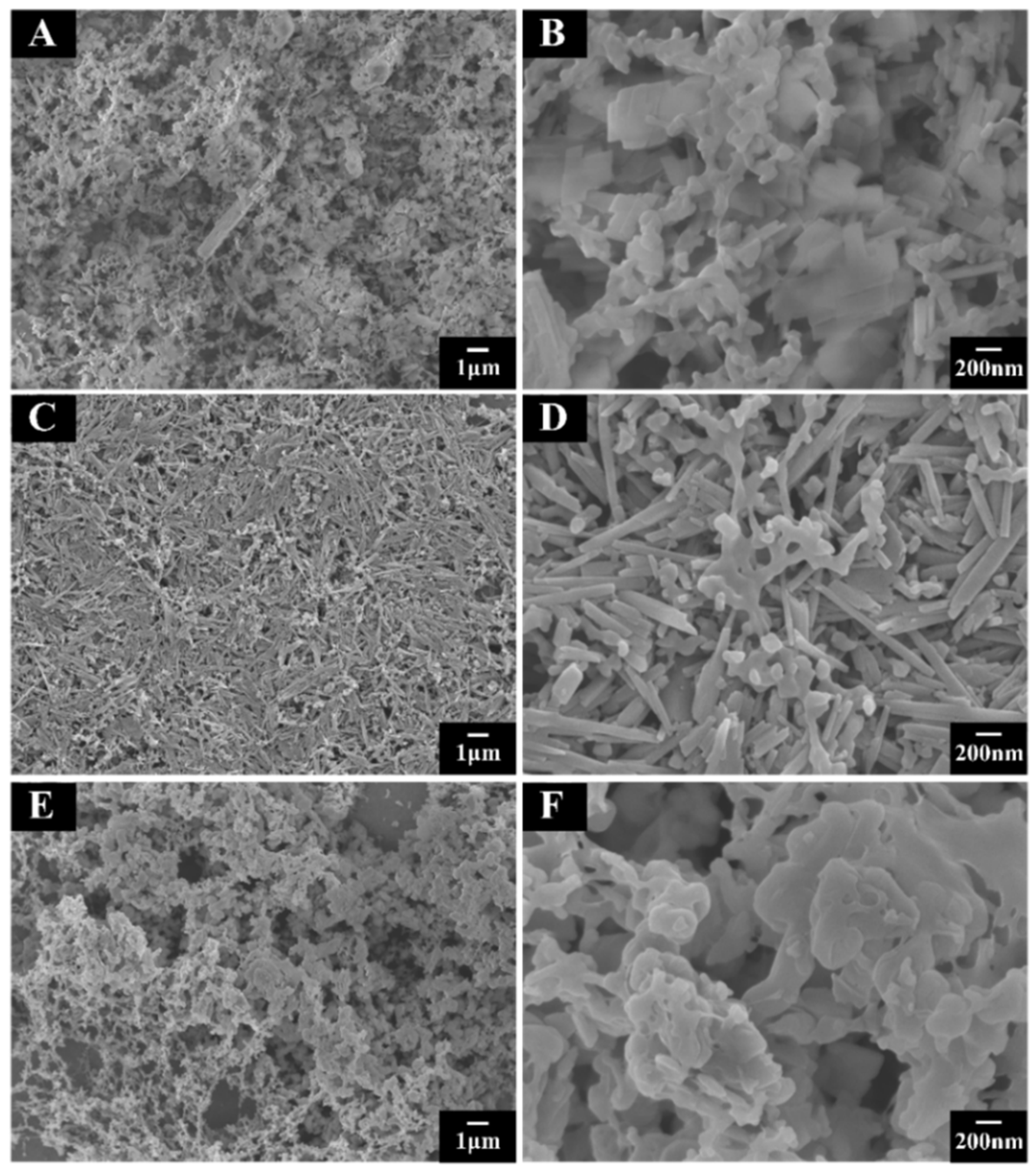
The PEMA-based composite coatings were deposited with three types of FRMs. The SEM images (Figure 3) at low magnification show a continuous porous composite coating formed by the dip-coating technique. The images at high magnification reveal the presence of FRM particles. Figure 3B shows the platelet morphology of huntite in the PEMA matrix. The halloysite nanotubes were densely packed, as shown in Figure 3D. Figure 3F shows submicrometre hydrotalcite particles embedding in the PEMA matrix. Voids were inevitable in the composite layers due to the packing of the FRM particles. The thickness of the coatings was about 2–2.5 μm.
The FTIR and XRD results confirm the successful fabrication of PEMA-FRM composite coatings. The spectrum of the as-received PEMA in Figure 4Aa shows absorptions at 2983, 1727, 1146, and 1023 cm−1 due to asymmetric C-H stretching, C=O stretching, C-O-C symmetric stretching, and C-H bending, respectively [39,40]. These four characteristic peaks can also be observed in the FTIR spectra of the composite coatings, as shown in Figure 4Ba–c. The FTIR spectrum of the as-received huntite (Figure 4Ab) shows characteristic absorptions at 1510, 1434, 894, and 864 cm−1, attributed to carbonate ligands [41,42,43,44].
The as-received halloysite showed peaks at 3692 and 3621 cm−1 due to the presence of the surface hydroxyl group (Figure 4Ac) [45]. The peaks at 1006, 906, and 525 cm−1 were ascribed to the stretching mode of Si-O-Si, the bending vibrations of Al-OH, and the bending and stretching vibrations of Si-O-Al, respectively [46,47]. The as-received hydrotalcite (Figure 4Ad) showed a peak at 3432 cm−1 due to the stretching mode of the hydroxy groups; the asymmetric stretching of the carbonate contributed to the peak at 1363 cm−1; the bands at 777, 648, and 553 cm−1 were assigned to oxygen–metal–oxygen stretching [48,49]. The spectra of the composite coatings show the absorptions of huntite (Figure 4Ba), halloysite (Figure 4Bb), and hydrotalcite (Figure 4Bc), in addition to the PEMA absorptions, and confirm FRM incorporation into the PEMA coatings.
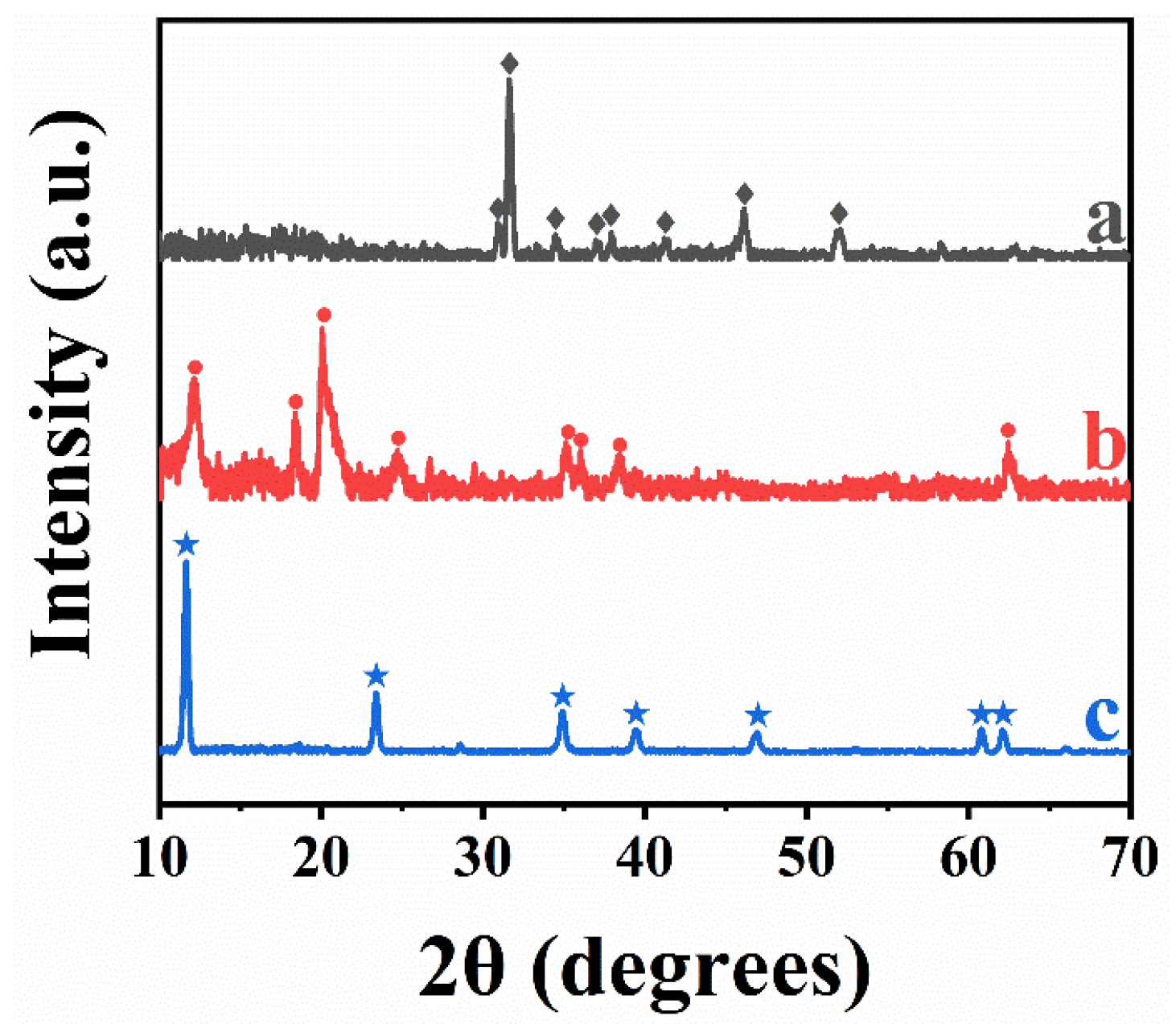
Figure 5 shows the XRD data for the composite coatings. The peaks of huntite, halloysite, and hydrotalcite were found in the XRD patterns of the composite coatings.
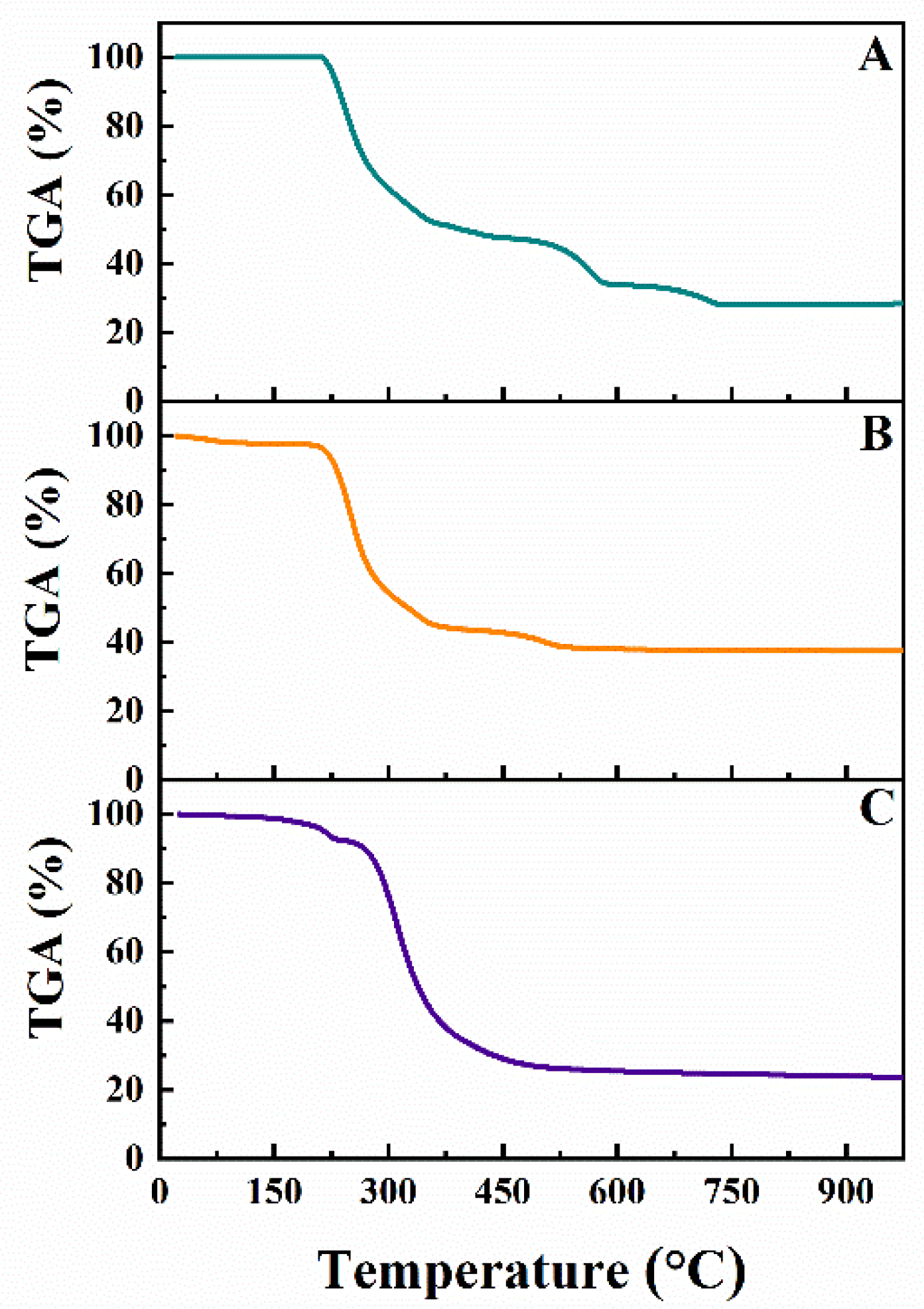
The composite coatings were studied by TGA. The TGA analysis of pure PEMA has been reported in several investigations [50,51,52,53,54]. It was found that PEMA decomposition started at 230 °C, and the complete burning out of PEMA was observed at 400 °C. Figure 6 shows several steps in the mass loss of composite coatings, related to the decomposition of FRMs and the burning out of PEMA. The total mass loss of PEMA-huntite at 900 °C was 76.5%. From the TGA data, the huntite content in the coating was found to be 46.9%. The total loss in mass of PEMA-halloysite was 62.6%, and the halloysite content in the composite was 49.5%. The mass loss for PEMA-hydrotalcite was 76.6%, and the hydrotalcite content in the composite coating was found to be 41.1%. The calculations of the FRM content in the composite coatings were based on the theoretical mass loss of 49.9, 24.5, and 43.1% for huntite, halloysite, and hydrotalcite, respectively. The experimental mass loss for such materials was very close to the theoretical mass loss [41,55,56].
Composite coatings are promising due to the possibility of combining corrosion protection and FRM properties. The experimental results presented above show enhanced corrosion protection of annealed PEMA. However, annealing at 200 °C can result in the partial decomposition of halloysite and hydrotalcite. Therefore, in this investigation, bi-layer coatings were prepared containing an annealed bottom layer of pure PEMA and an as-deposited composite PEMA-FRM layer. The microstructure of the PEMA-FRM layers deposited on the annealed PEMA layers (Figure S2) was similar to the microstructure of the PEMA-FRM layers deposited directly on stainless steel (Figure 3). Dip coating is a versatile method [57] for the fabrication of composite and multilayer coatings. It is known that multilayer and functionally graded materials offer advantages in the fabrication of composites with enhanced functional properties [58,59]. In contrast to other techniques, such as electrophoretic deposition [60,61], dip coatings can be obtained on conductive and insulating substrates.
Figure 7 compares the results of the potentiodynamic testing of monolayer PEMA-FRM coatings and bi-layer coatings containing an annealed bottom PEMA layer and a top PEMA-FRM layer. The comparison of Tafel plots for PEMA-FRM-coated substrates (Figure 7Aa,Ba,Ca) with the corresponding data for uncoated samples (Figure 2Aa) indicates that PEMA-FRM coatings provide corrosion protection of the substrates. The coated samples showed lower anodic currents compared to uncoated samples and higher corrosion potentials. As hypothesised, the bi-layer coatings provided improved corrosion protection compared to the monolayer coatings. The Tafel plots show a further reduction in the anodic current compared to the monolayer coatings (Figure 7Ab,Bb,Cb). The corresponding Bode plots are presented in Figure 8.
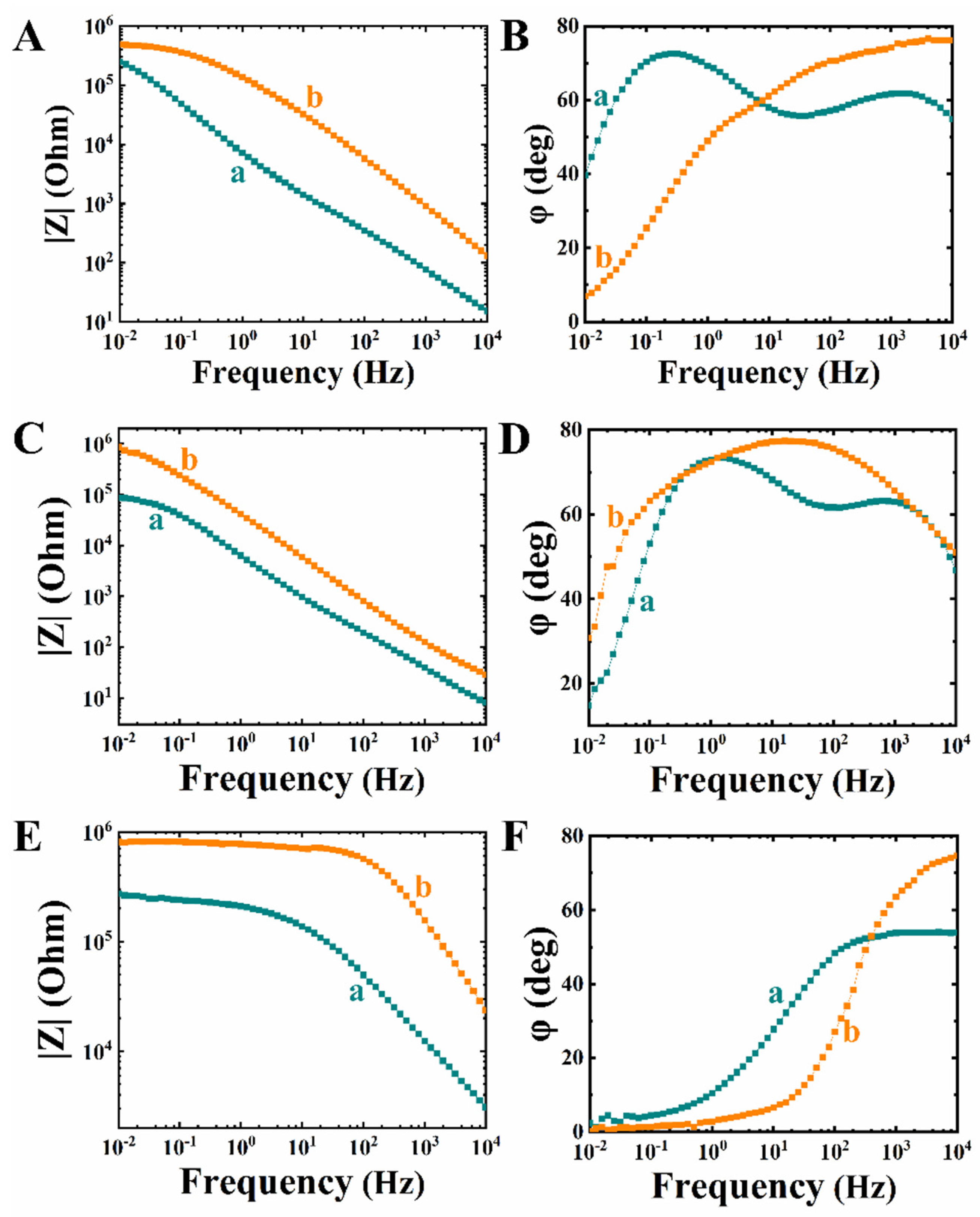
The Bode plots for the monolayer PEMA-FRM coatings show enhanced impedance |Z| (Figure 8Aa,Ca,Ea) compared to uncoated stainless steel (Figure 2Ba). The bi-layer coating showed higher |Z| (Figure 8Ab,Cb,Eb) compared to the monolayer coatings. Therefore, bi-layer coatings represent an enhanced barrier for electrolyte diffusion.

4. Conclusions

The approach developed in this investigation offers the benefits of using a non-toxic co-solvent and the replacement of regular toxic solvents for PEMA. The use of advanced inorganic FRM materials, such as huntite, halloysite, and hydrotalcite, instead of toxic halogenated FRMs offers additional environmental benefits. The ability to obtain concentrated solutions of high-molecular-mass PEMA and disperse FRM particles in such solutions plays a vital role in the fabrication of coatings using a dip-coating method. SEM, TGA, XRD, and FTIR studies confirmed the fabrication of composite coatings with a large FRM content. Pure PEMA and PEMA-FRM coatings provide corrosion protection of stainless steel. Annealed PEMA coatings provide enhanced corrosion protection due to lower porosity. The ability to form composite laminates containing different layers using a dip-coating method is a promising strategy for the fabrication of composite coatings with enhanced functionality.

Supplementary Materials

The following are available online at https://www.mdpi.com/article/10.3390/jcs6040104/s1, Figure S1: SEM images of (A) as-deposited coatings and (B) coatings annealed at 200 °C for 1 h, prepared from 10 g L−1 PEMA solutions. Figure S2. SEM images at different magnifications of as-deposited bi-layer composite coatings, containing annealed PEMA bottom layer and PEMA-FRM top layer with (A,B) huntite, (C,D) halloysite, and (E,F) hydrotalcite.

Author Contributions

Conceptualisation, X.L., I.Z. and S.V.; methodology, X.L.; software, X.L.; validation, X.L., R.M. and I.Z.; formal analysis, X.L.; investigation, X.L.; resources, S.V. and R.M.; data curation, X.L.; writing—original draft preparation, X.L. and I.Z.; writing—review and editing, X.L. and I.Z.; visualisation, X.L.; supervision, S.V. and I.Z.; project administration, I.Z.; funding acquisition, S.V., R.M. and I.Z. All authors have read and agreed to the published version of the manuscript.

Funding

This research was funded by the Natural Sciences and Engineering Research Council of Canada, grant number RGPIN-2018-04014, and the CRC program.

Institutional Review Board Statement

Not applicable.

Informed Consent Statement

Not applicable.

Data Availability Statement

The data presented in this study are available in this paper and Supplementary Materials.

Acknowledgments

SEM investigations were performed at the Canadian Centre for Electron Microscopy.

Conflicts of Interest

The authors declare no conflict of interest.

References

  1. Chen, L.; Wang, Y.Z. A review on flame retardant technology in China. Part I: Development of flame retardants. Polym. Adv. Technol. 2010, 21, 1–26. [Google Scholar] [CrossRef]
  2. Lu, H.; Song, L.; Hu, Y. A review on flame retardant technology in China. Part II: Flame retardant polymeric nanocomposites and coatings. Polym. Adv. Technol. 2011, 22, 379–394. [Google Scholar] [CrossRef]
  3. Gordon, K.L.; Thompson, C.M.; Lyon, R.E. Flame retardant epoxy resins containing aromatic poly(phosphonamides). High Perform. Polym. 2010, 22, 945–958. [Google Scholar] [CrossRef]
  4. Weil, E.D. Fire-Protective and Flame-Retardant Coatings-A State-of-the-Art Review. J. Fire Sci. 2011, 29, 259–296. [Google Scholar] [CrossRef]
  5. Wang, Z.T.; Luo, Y.K.; Ding, X.; Xi, G.F. The Research on Flame Retardant Wind Turbines Nacelle Made through VARTM Process. Adv. Mater. Res. 2012, 450, 508–512. [Google Scholar] [CrossRef]
  6. Xu, T.; Huang, X. Combustion properties of asphalt binder containing flame retardant. Fire Mater. 2012, 36, 97–106. [Google Scholar] [CrossRef]
  7. Wang, S.; Huang, J.; Chen, F. Study on mg-al hydrotalcites in flame retardant paper preparation. BioResources 2012, 7, 997–1007. [Google Scholar]
  8. Nam, N.D.; Park, I.J.; Kim, J.G.; Kim, H.S. Effect of flame-retarding additives on surface chemistry in Li-ion batteries. Mater. Res. Bull. 2012, 47, 2811–2814. [Google Scholar] [CrossRef]
  9. Chen, S.; Wang, Z.; Zhao, H.; Qiao, H.; Luan, H.; Chen, L. A novel flame retardant and film-forming electrolyte additive for lithium ion batteries. J. Power Sources 2009, 187, 229–232. [Google Scholar] [CrossRef]
  10. Hamdani, S.; Longuet, C.; Perrin, D.; Lopez-cuesta, J.-M.; Ganachaud, F.O. Flame retardancy of silicone-based materials. Polym. Degrad. Stab. 2009, 94, 465–495. [Google Scholar] [CrossRef]
  11. Mouritz, A.P. Review of smoke toxicity of fiber-polymer composites used in aircraft. J. Aircr. 2009, 46, 735–745. [Google Scholar] [CrossRef]
  12. Holbery, J.; Houston, D. Natural-fiber-reinforced polymer composites in automotive applications. JOM 2006, 58, 80–86. [Google Scholar] [CrossRef]
  13. Ding, P.; Tang, S.; Yang, H.; Shi, L. PP/LDH nanocomposites via melt-intercalation: Synergistic flame retardant effects, properties, and applications in automobile industries. Adv. Mater. Res. 2010, 87–88, 427–432. [Google Scholar] [CrossRef]
  14. Laoutid, F.; Bonnaud, L.L.; Alexandre, M.L.; Lopez-Cuesta, J.-M.; Dubois, P. New prospects in flame retardant polymer materials: From fundamentals to nanocomposites. Mater. Sci. Eng. R Rep. 2009, 63, 100–125. [Google Scholar] [CrossRef]
  15. Camino, G.; Costa, L.; Martinasso, G. Intumescent fire-retardant systems. Polym. Degrad. Stab. 1989, 23, 359–376. [Google Scholar] [CrossRef]
  16. Camino, G.; Costa, L.; Luda di Cortemiglia, M. Overview of fire retardant mechanisms. Polym. Degrad. Stab. 1991, 33, 131–154. [Google Scholar] [CrossRef]
  17. Wilford, B.H.; Shoeib, M.; Harner, T.; Zhu, J.; Jones, K.C. Polybrominated diphenyl ethers in indoor dust in Ottawa, Canada: Implications for sources and exposure. Environ. Sci. Technol. 2005, 39, 7027–7035. [Google Scholar] [CrossRef]
  18. Porter, D.; Metcalfe, E.; Thomas, M. Nanocomposite fire retardants—A review. Fire Mater. 2000, 24, 45–52. [Google Scholar] [CrossRef]
  19. Clement, R.E.; Reiner, E.J.; Bhavsar, S.P. Organohalogen contaminants of emerging concern in Great Lakes fish: A review. Anal. Bioanal. Chem. 2012, 404, 2639–2658. [Google Scholar] [CrossRef]
  20. Shoeib, M.; Harner, T.; Webster, G.M.; Sverko, E.; Cheng, Y. Legacy and current-use flame retardants in house dust from Vancouver, Canada. Environ. Pollut. 2012, 169, 175–182. [Google Scholar] [CrossRef]
  21. Gentes, M.-L.; Letcher, R.J.; Caron-Beaudoin, E.; Verreault, J. Novel flame retardants in urban-feeding ring-billed gulls from the St. Lawrence River, Canada. Environ. Sci. Technol. 2012, 46, 9735–9744. [Google Scholar] [CrossRef] [PubMed]
  22. Chen, D.; Letcher, R.J.; Burgess, N.M.; Champoux, L.; Elliott, J.E.; Hebert, C.E.; Martin, P.; Wayland, M.; Chip Weseloh, D.V.; Wilson, L. Flame retardants in eggs of four gull species (Laridae) from breeding sites spanning Atlantic to Pacific Canada. Environ. Pollut. 2012, 168, 1–9. [Google Scholar] [CrossRef] [PubMed]
  23. Alava, J.J.; Lambourn, D.; Olesiuk, P.; Lance, M.; Jeffries, S.J.; Gobas, F.A.P.C.; Ross, P.S. PBDE flame retardants and PCBs in migrating Steller sea lions (Eumetopias jubatus) in the Strait of Georgia, British Columbia, Canada. Chemosphere 2012, 88, 855–864. [Google Scholar] [CrossRef] [PubMed]
  24. Wong, F.; Kurt-Karakus, P.; Bidleman, T.F. Fate of brominated flame retardants and organochlorine pesticides in urban soil: Volatility and degradation. Environ. Sci. Technol. 2012, 46, 2668–2674. [Google Scholar] [CrossRef] [PubMed]
  25. Xiao, H.; Shen, L.; Su, Y.; Barresi, E.; Dejong, M.; Hung, H.; Lei, Y.-D.; Wania, F.; Reiner, E.J.; Sverko, E.; et al. Atmospheric concentrations of halogenated flame retardants at two remote locations: The Canadian High Arctic and the Tibetan Plateau. Environ. Pollut. 2012, 161, 154–161. [Google Scholar] [CrossRef]
  26. Ivol, F.; Porcher, M.; Ghosh, A.; Jacquemin, J.; Ghamouss, F. Phenylacetonitrile (C6H5CH2CN) Ionic Liquid Blends as Alternative Electrolytes for Safe and High-Performance Supercapacitors. Molecules 2020, 25, 2697. [Google Scholar] [CrossRef]
  27. McDonough, C.A.; Puggioni, G.; Helm, P.A.; Muir, D.; Lohmann, R. Spatial Distribution and Air–Water Exchange of Organic Flame Retardants in the Lower Great Lakes. Environ. Sci. Technol. 2016, 50, 9133–9141. [Google Scholar] [CrossRef]
  28. Venier, M.; Dove, A.; Romanak, K.; Backus, S.; Hites, R. Flame retardants and legacy chemicals in Great Lakes’ water. Environ. Sci. Technol. 2014, 48, 9563–9572. [Google Scholar] [CrossRef]
  29. Yang, J.; Liang, J.Z.; Tang, C.Y. Studies on melt flow properties during capillary extrusion of PP/Al(OH)3/Mg(OH)2 flame retardant composites. Polym. Test. 2009, 28, 907–911. [Google Scholar] [CrossRef]
  30. Jizhao, L.; Yingjie, Z. A study of the flame-retardant properties of polypropylene/Al(OH)3/Mg(OH)2 composites. Polym. Int. 2010, 59, 539–542. [Google Scholar]
  31. Armstrong, R.; Wright, J. Impedance studies of poly ethylmethacrylate coatings formed upon tin-free steel. Corros. Sci. 1992, 33, 1529–1539. [Google Scholar] [CrossRef]
  32. Sari, A.; Karlı, A.; Alkan, C.; Karaipekli, A. Polyethyl methacrylate (PEMA)/fatty acids blends as novel phase change materials for thermal energy storage. Energy Sources Part A Recovery Util. Environ. Eff. 2013, 35, 1813–1819. [Google Scholar] [CrossRef]
  33. Ulaganathan, M.; Mathew, C.M.; Rajendran, S. Highly porous lithium-ion conducting solvent-free poly (vinylidene fluoride-co-hexafluoropropylene)/poly (ethyl methacrylate) based polymer blend electrolytes for Li battery applications. Electrochim. Acta 2013, 93, 230–235. [Google Scholar] [CrossRef]
  34. Ramesh, S.; Uma, O.; Shanti, R.; Yi, L.J.; Ramesh, K. Preparation and characterization of poly (ethyl methacrylate) based polymer electrolytes doped with 1-butyl-3-methylimidazolium trifluoromethanesulfonate. Measurement 2014, 48, 263–273. [Google Scholar] [CrossRef]
  35. Mohanty, F.; Swain, S.K. Silver Nanoparticles Decorated Polyethylmethacrylate/Graphene Oxide Composite: As Packaging Material. Polym. Compos. 2019, 40, E1199–E1207. [Google Scholar] [CrossRef]
  36. Mohanty, F.; Swain, S.K. Nano silver embedded starch hybrid graphene oxide sandwiched poly (ethylmethacrylate) for packaging application. Nano-Struct. Nano-Objects 2019, 18, 100300. [Google Scholar] [CrossRef]
  37. Arnold, J.C.; Venditti, N.P. Prediction of the long-term creep behaviour of hydroxyapatite-filled polyethylmethacrylate bone cements. J. Mater. Sci. Mater. Med. 2007, 18, 1849–1858. [Google Scholar] [CrossRef]
  38. Peng, Y.; Musah, M.; Via, B.; Wang, X. Calcium Carbonate Particles Filled Homopolymer Polypropylene at Different Loading Levels: Mechanical Properties Characterization and Materials Failure Analysis. J. Compos. Sci. 2021, 5, 302. [Google Scholar] [CrossRef]
  39. Li, X.; Zhitomirsky, I. Deposition of poly (methyl methacrylate) and composites containing bioceramics and bioglass by dip coating using isopropanol-water co-solvent. Prog. Org. Coat. 2020, 148, 105883. [Google Scholar] [CrossRef]
  40. Jankovic, I.A.; Saponjic, Z.V.; Comor, M.I.; Nedeljkovic, J.M. Surface modification of colloidal TiO2 nanoparticles with bidentate benzene derivatives. J. Phys. Chem. C 2009, 113, 12645–12652. [Google Scholar] [CrossRef]
  41. Zhang, T.; Luo, D.; Wojtal, P.; Zhitomirsky, I. Electrophoretic deposition of flame retardant polymer–Huntite coatings. Mater. Lett. 2015, 159, 106–109. [Google Scholar] [CrossRef]
  42. Şen, F.; Madakbaş, S.; Kahraman, M.V. Preparation and characterization of polyaniline/Turkish Huntite–Hydromagnesite composites. Polym. Compos. 2014, 35, 456–460. [Google Scholar] [CrossRef]
  43. Madakbaş, S.; Celik, Z.; Dumludağ, F.; Kahraman, M.V. Preparation, characterization and electrical properties of polyacrylonitrile/huntite composites. Polym. Bull. 2014, 71, 1471–1481. [Google Scholar] [CrossRef]
  44. Seki, Y.; Sever, K.; Sarikanat, M.; Sakarya, A.; Elik, E. Effect of huntite mineral on mechanical, thermal and morphological properties of polyester matrix. Compos. Part B Eng. 2013, 45, 1534–1540. [Google Scholar] [CrossRef]
  45. Zainuddin, S.; Fahim, A.; Shoieb, S.; Syed, F.; Hosur, M.V.; Li, D.; Hicks, C.; Jeelani, S. Morphological and mechanical behavior of chemically treated jute-PHBV bio-nanocomposites reinforced with silane grafted halloysite nanotubes. J. Appl. Polym. Sci. 2016, 133. [Google Scholar] [CrossRef]
  46. Li, C.; Zhao, Y.; Zhu, T.; Ruan, J.; Li, G. Effective solvent-free oxidation of cyclohexene to allylic products with oxygen by mesoporous etched halloysite nanotube supported Co2+. RSC Adv. 2018, 8, 14870–14878. [Google Scholar] [CrossRef] [Green Version]
  47. Li, X.; Wang, Z.; Sakib, S.; Mathews, R.; Zhitomirsky, I. Poly (Methyl Methacrylate) Coatings Containing Flame Retardant Additives from Suspensions in Water-2-Propanol. Molecules 2021, 26, 1974. [Google Scholar] [CrossRef]
  48. González, M.A.; Trócoli, R.; Pavlovic, I.; Barriga, C.; La Mantia, F. Capturing Cd (II) and Pb (II) from contaminated water sources by electro-deposition on hydrotalcite-like compounds. Phys. Chem. Chem. Phys. 2016, 18, 1838–1845. [Google Scholar] [CrossRef]
  49. Tian, X.; Wang, J.; Zhang, H.; Cao, Z.; Zhao, M.; Guan, Y.; Zhang, Y. Establishment of transport channels with carriers for water in reverse osmosis membrane by incorporating hydrotalcite into the polyamide layer. RSC Adv. 2018, 8, 12439–12448. [Google Scholar] [CrossRef] [Green Version]
  50. Abdelrazek, E.; Elashmawi, I. Characterization and physical properties of CoCl2 filled polyethyl-methacrylate films. Polym. Compos. 2008, 29, 1036–1043. [Google Scholar] [CrossRef]
  51. Gradwell, M.; Hourston, D.; Pabunruang, T.; Schafer, F.U.; Reading, M. High-resolution thermogravimetric analysis of polyurethane/poly (ethyl methacrylate) interpenetrating polymer networks. J. Appl. Polym. Sci. 1998, 70, 287–295. [Google Scholar] [CrossRef]
  52. Agrawal, M.; Zafeiropoulos, N.E.; Gupta, S.; Svetushkina, E.; Pionteck, J.; Pich, A.; Stamm, M. A novel approach for mixing ZnO nanoparticles into poly (ethyl methacrylate). Macromol. Rapid Commun. 2010, 31, 405–410. [Google Scholar] [CrossRef] [PubMed]
  53. Rajendran, S.; Prabhu, M.R.; Rani, M.U. Characterization of PVC/PEMA based polymer blend electrolytes. Int. J. Electrochem. Sci. 2008, 3, 282–290. [Google Scholar]
  54. Sim, L.; Majid, S.; Arof, A. Effects of 1–butyl–3–methyl imidazolium trifluoromethanesulfonate ionic liquid in poly (ethyl methacrylate)/poly (vinylidenefluoride–co–hexafluoropropylene) blend based polymer electrolyte system. Electrochim. Acta 2014, 123, 190–197. [Google Scholar] [CrossRef]
  55. Sun, Y.; Ata, M.; Zhitomirsky, I. Electrophoretic deposition of linear polyethylenimine and composite films. Surf. Eng. 2013, 29, 495–499. [Google Scholar] [CrossRef]
  56. Nicolini, K.P.; Fukamachi, C.R.B.; Wypych, F.; Mangrich, A.S. Dehydrated halloysite intercalated mechanochemically with urea: Thermal behavior and structural aspects. J. Colloid Interface Sci. 2009, 338, 474–479. [Google Scholar] [CrossRef]
  57. Peng, Y.; Burtovyy, R.; Bordia, R.; Luzinov, I. Fabrication of Porous Carbon Films and Their Impact on Carbon/Polypropylene Interfacial Bonding. J. Compos. Sci. 2021, 5, 108. [Google Scholar] [CrossRef]
  58. Garcia Filho, F.C.; Luz, F.S.; Oliveira, M.S.; Bezerra, W.B.A.; Barbosa, J.D.V.; Monteiro, S.N. Influence of Rigid Brazilian Natural Fiber Arrangements in Polymer Composites: Energy Absorption and Ballistic Efficiency. J. Compos. Sci. 2021, 5, 201. [Google Scholar] [CrossRef]
  59. Tsukamoto, H. Tribological Characterization of Carbon Nanotube/Aluminum Functionally Graded Materials Fabricated by Centrifugal Slurry Methods. J. Compos. Sci. 2021, 5, 254. [Google Scholar] [CrossRef]
  60. Su, Y.; Zhitomirsky, I. Electrophoretic deposition of graphene, carbon nanotubes and composite films using methyl violet dye as a dispersing agent. Colloids Surf. A Physicochem. Eng. Asp. 2013, 436, 97–103. [Google Scholar] [CrossRef]
  61. Wu, K.; Wang, Y.; Zhitomirsky, I. Electrophoretic deposition of TiO2 and composite TiO2–MnO2 films using benzoic acid and phenolic molecules as charging additives. J. Colloid Interface Sci. 2010, 352, 371–378. [Google Scholar] [CrossRef] [PubMed]
Figure 1. SEM images of (A) as-deposited coatings and (B) coatings annealed at 200 °C for 1 h, prepared from 20 g L−1 PEMA solutions.
Jcs 06 00104 g001
Figure 2. (A) Tafel and (B,C) Bode plots for (a) uncoated and (b,c) coated substrate: (b) as-deposited coatings and (c) coatings annealed at 200 °C for 1 h, prepared from 20 g L−1 PEMA solutions.
Jcs 06 00104 g002
Figure 3. SEM images at different magnifications of as-deposited monolayer composite coatings: (A,B) PEMA-huntite, (C,D) PEMA-halloysite, and (E,F) PEMA-hydrotalcite.
Jcs 06 00104 g003
Figure 4. FTIR spectra of (A) as-received materials, namely, (a) PEMA, (b) huntite, (c) halloysite, and (d) hydrotalcite, and (B) as-deposited composite coatings, namely, (a) PEMA-huntite, (b) PEMA-halloysite, and (c) PEMA-hydrotalcite.
Jcs 06 00104 g004
Figure 5. XRD patterns of as-deposited composite coatings: (a) PEMA-huntite, (b) PEMA-halloysite, and (c) PEMA-hydrotalcite (♦—JCPDS file 14-0409, ●—JCPDS file 09-0453, ★—JCPDS file 50-1684).
Jcs 06 00104 g005
Figure 6. TGA data for as-deposited composite coatings: (A) PEMA-huntite, (B) PEMA-halloysite, and (C) PEMA-hydrotalcite.
Jcs 06 00104 g006
Figure 7. Tafel plots for as-deposited (a) monolayer PEMA-FRM coatings and (b) bi-layer composite coatings containing annealed PEMA bottom layer and PEMA-FRM top layer with (A) huntite, (B) halloysite, and (C) hydrotalcite.
Jcs 06 00104 g007
Figure 8. Bode plots for as-deposited (a) monolayer PEMA-FRM coatings and (b) bi-layer composite coatings containing annealed PEMA bottom layer and PEMA-FRM top layer with (A,B) huntite, (C,D) halloysite, and (E,F) hydrotalcite.
Jcs 06 00104 g008
Publisher’s Note: MDPI stays neutral with regard to jurisdictional claims in published maps and institutional affiliations.