
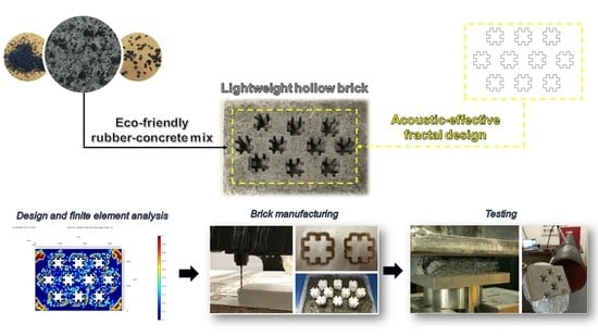
Finite Element Multi-Physics Analysis and Experimental Testing for Hollow Brick Solutions with Lightweight and Eco-Sustainable Cement Mix

 ,
,  ,
, 

Abstract
:
1. Introduction
- The dead load is much lower than for a solid block; due to this, one can structurally engineer them and reduce steel consumption in construction;
- The heat insulation of wall structures is achieved due to the inner cavities, which provide energy saving for all times. Similarly, hollowness results in improved sound attenuation;
- Low maintenance cost, minimal material requirements, and cost competitiveness with other materials make it a preferred material for today’s building.
- Part 1—Description and key properties of the cement mixes (reference and rubberized concretes) used for hollow bricks manufacturing;
- Part 2—Design, topological optimization, and finite element modeling (mechanical and acoustic analysis) of hollow brick prototypes based on circular and fractal inner cavities;
- Part 3—Production process of the designed hollow bricks, mechanical and acoustic experimental characterization, and FEA models validation.
2. Materials and Methods
2.1. Part 1: Raw Materials and Concrete Mixes Characterization
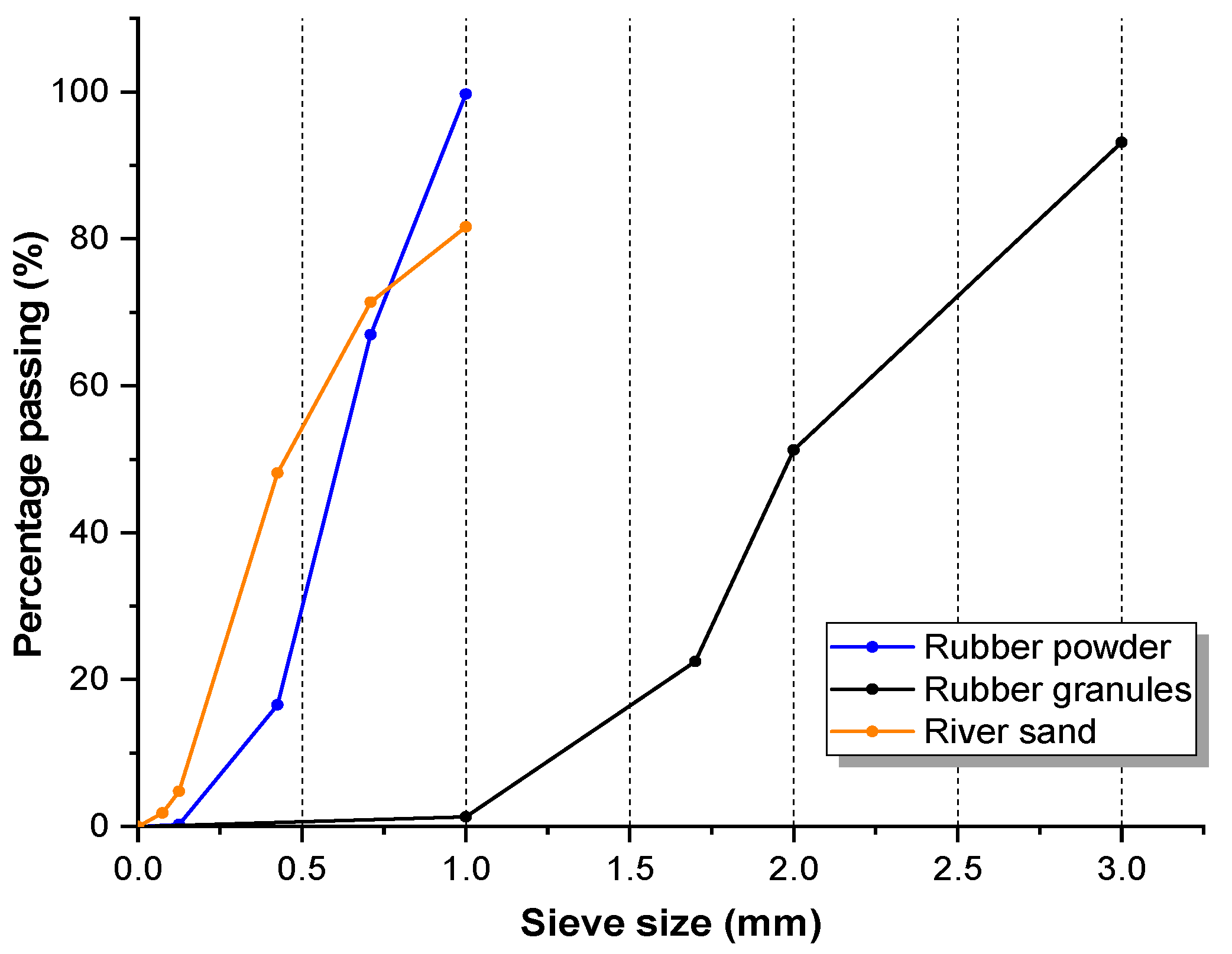
2.1.1. Raw Materials
2.1.2. Mix Proportions and Samples Preparation
2.1.3. Testing Program and Experimental Results
2.2. Part 2: Design, Modeling, and FEA of Hollow Bricks
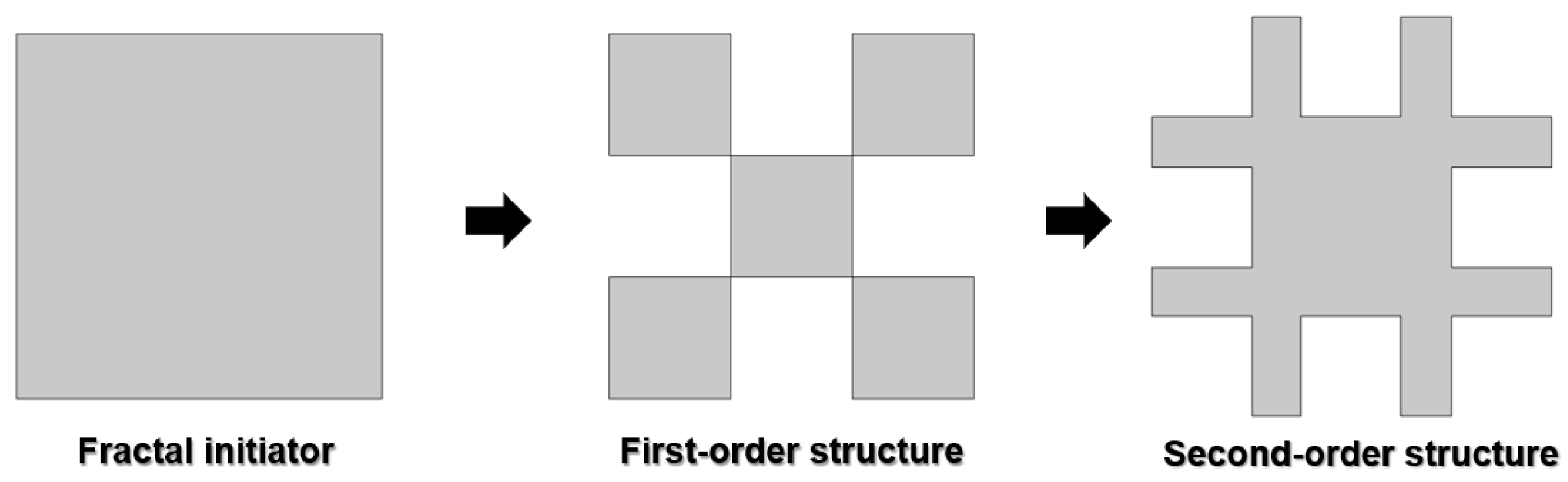
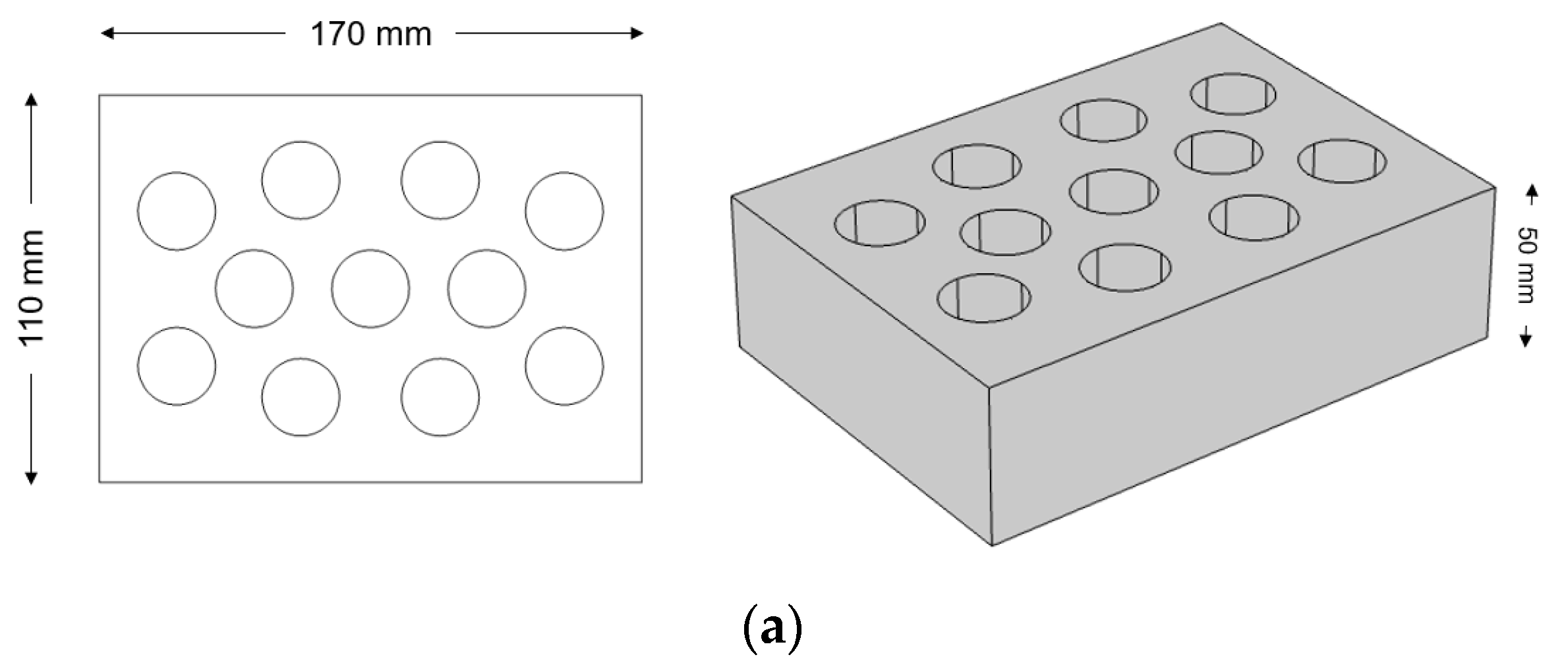
2.2.1. Hollow Bricks Design
- Hole area <1200 mm2;
- Minimum hole-external-perimeter distance >15 mm;
- Minimum distance between adjacent holes >8 mm.
2.2.2. FEA-Based Mechanical Analysis
Definition of the Problem
Mathematical Modeling
Material Properties
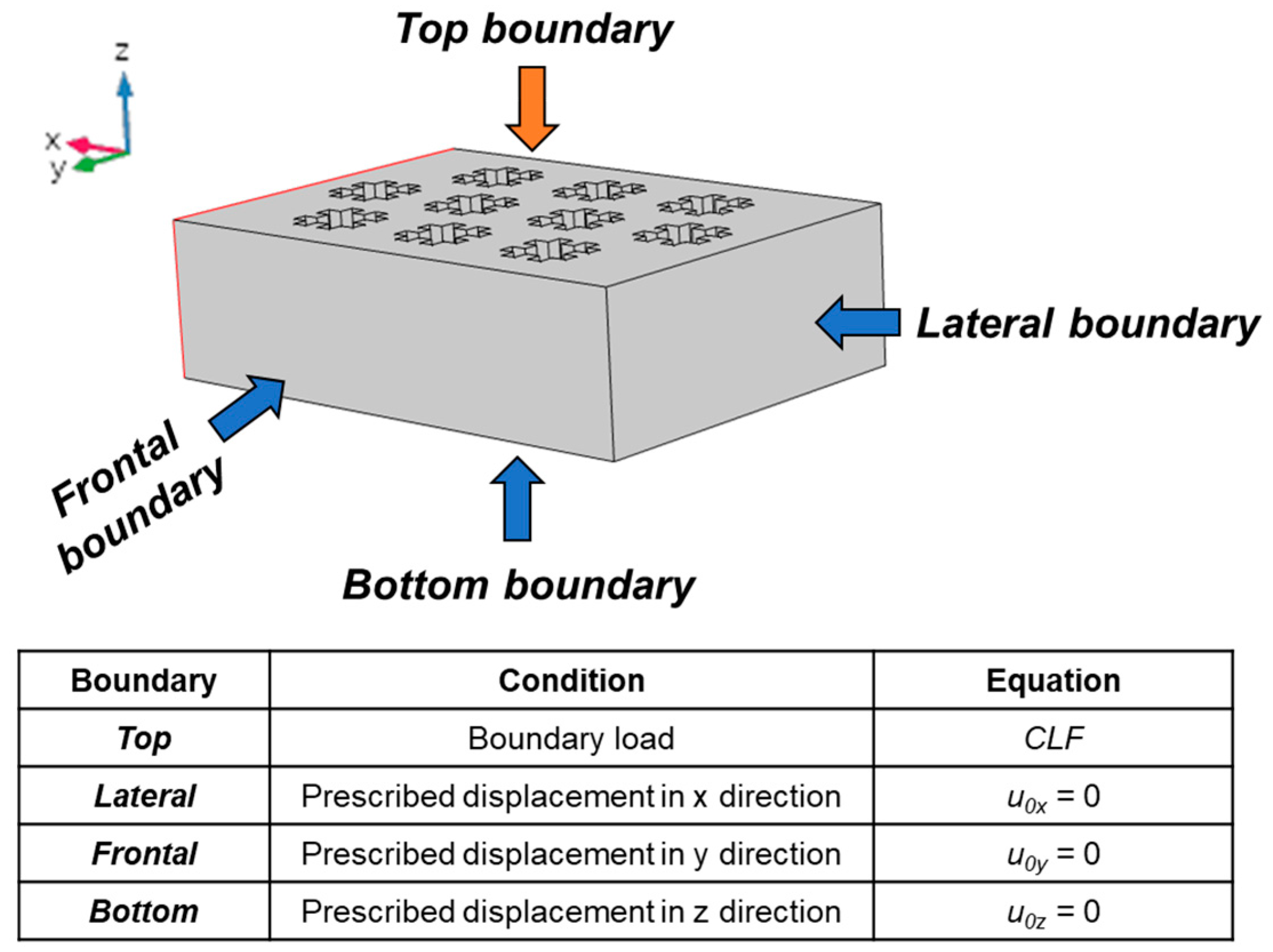
Boundary Conditions
2.2.3. FEA-Based Acoustic Analysis
Definition of the Problem
Mathematical Modeling
Material Properties
Boundary Conditions
2.3. Part 3: Hollow-Brick Production and Testing
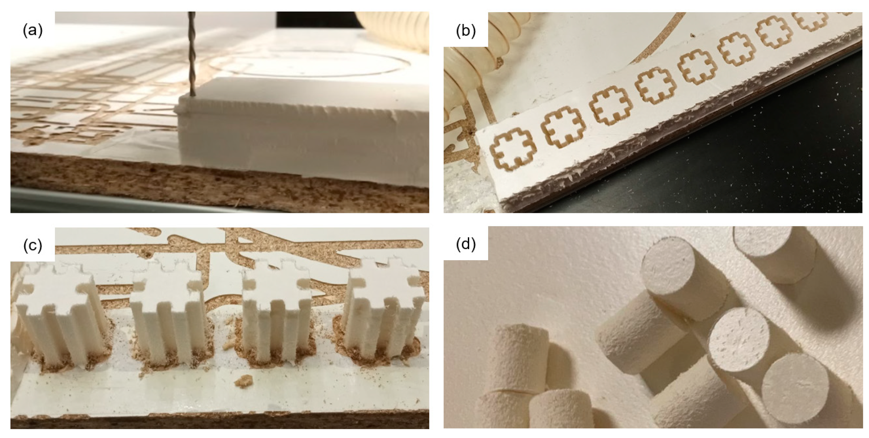
2.3.1. Fabrication of the Brick Mold
2.3.2. Casting and Bricks Manufacturing
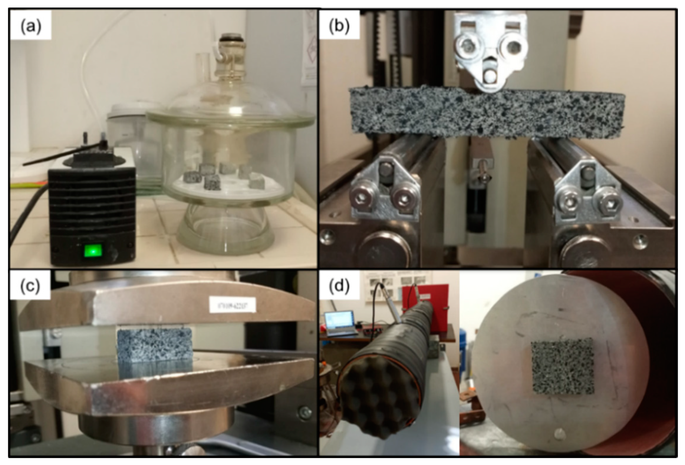
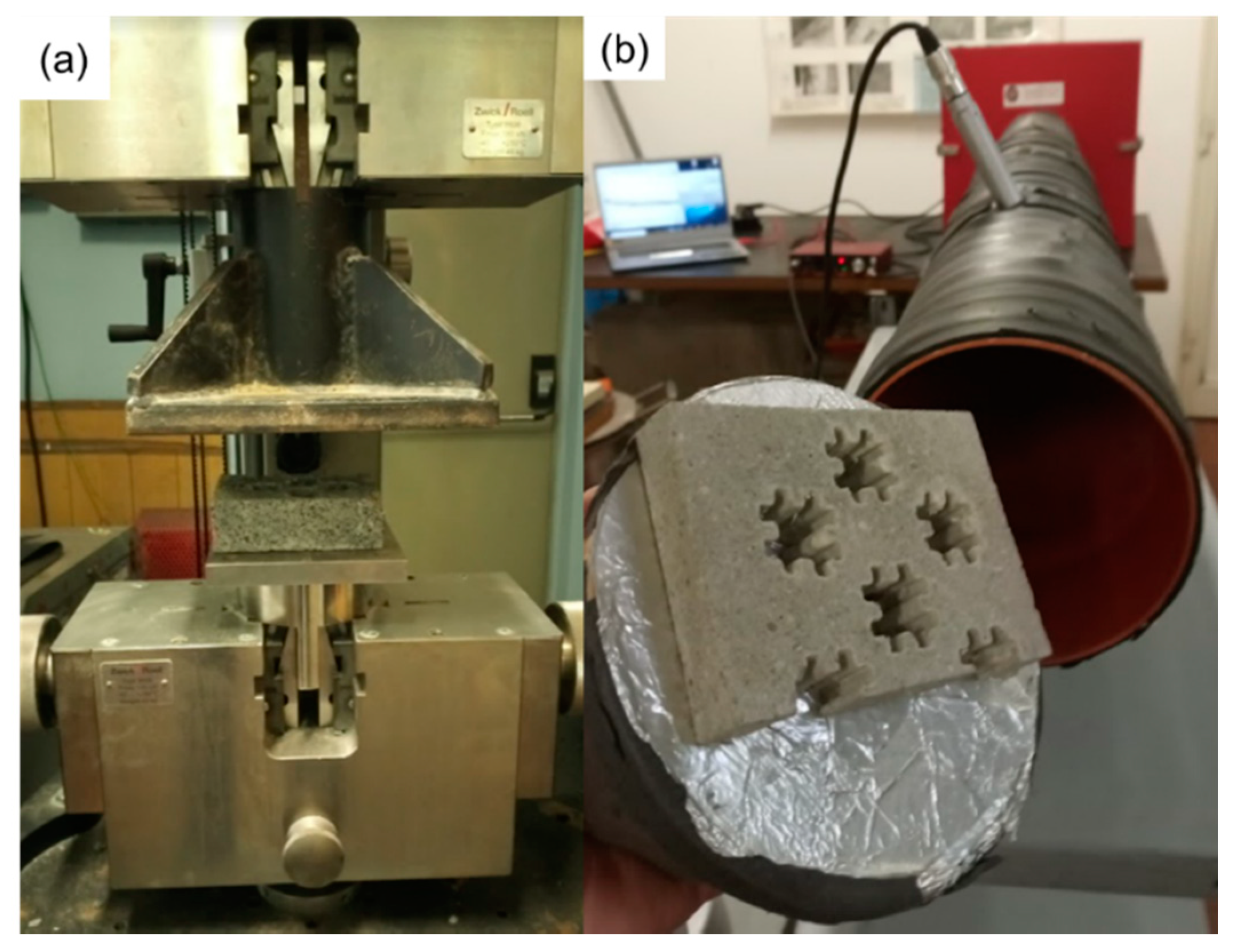
2.3.3. Testing
3. Results
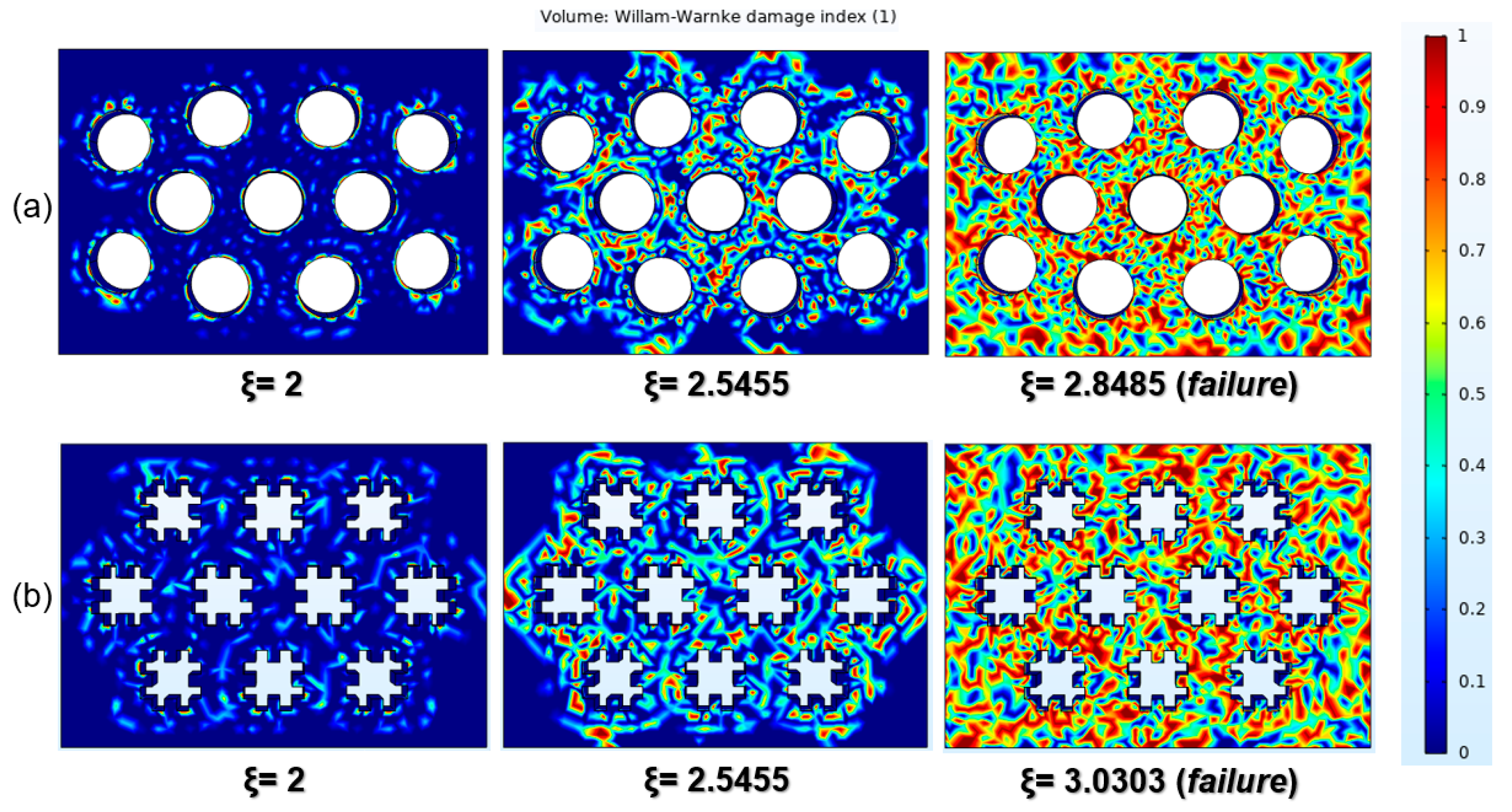
3.1. FEA-Based Mechanical Analysis
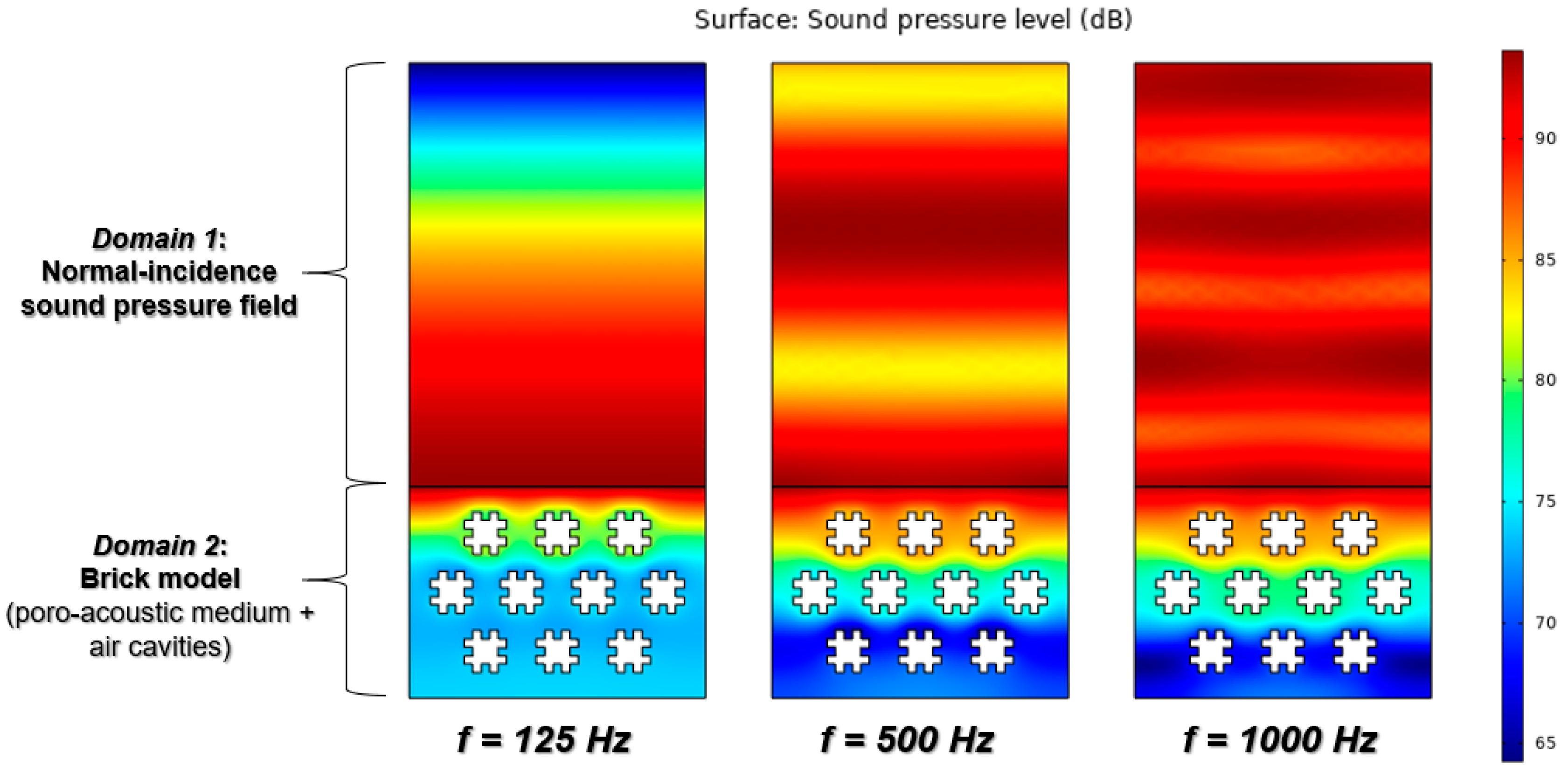
3.2. FEA-Based Acoustic Analysis
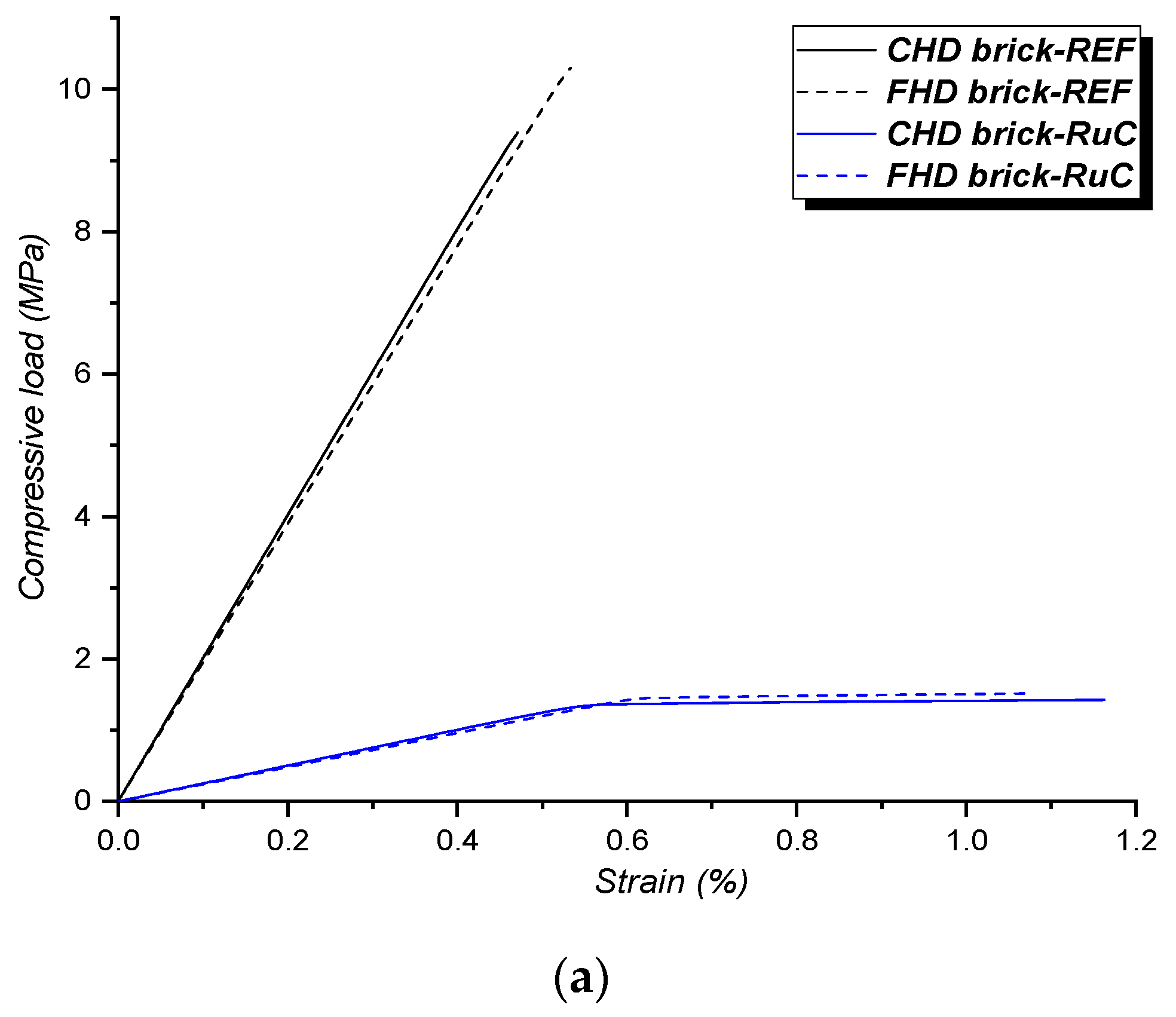
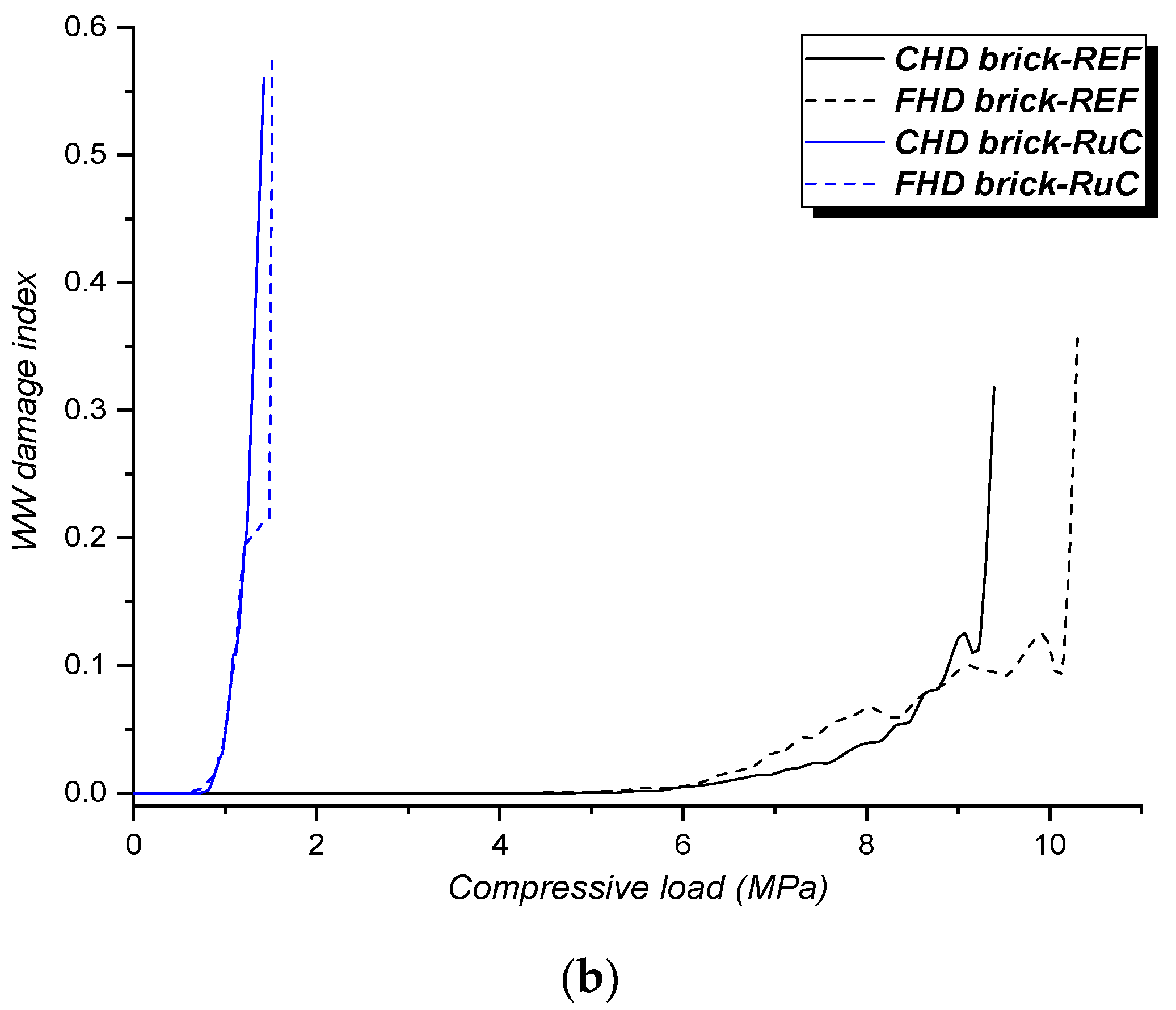
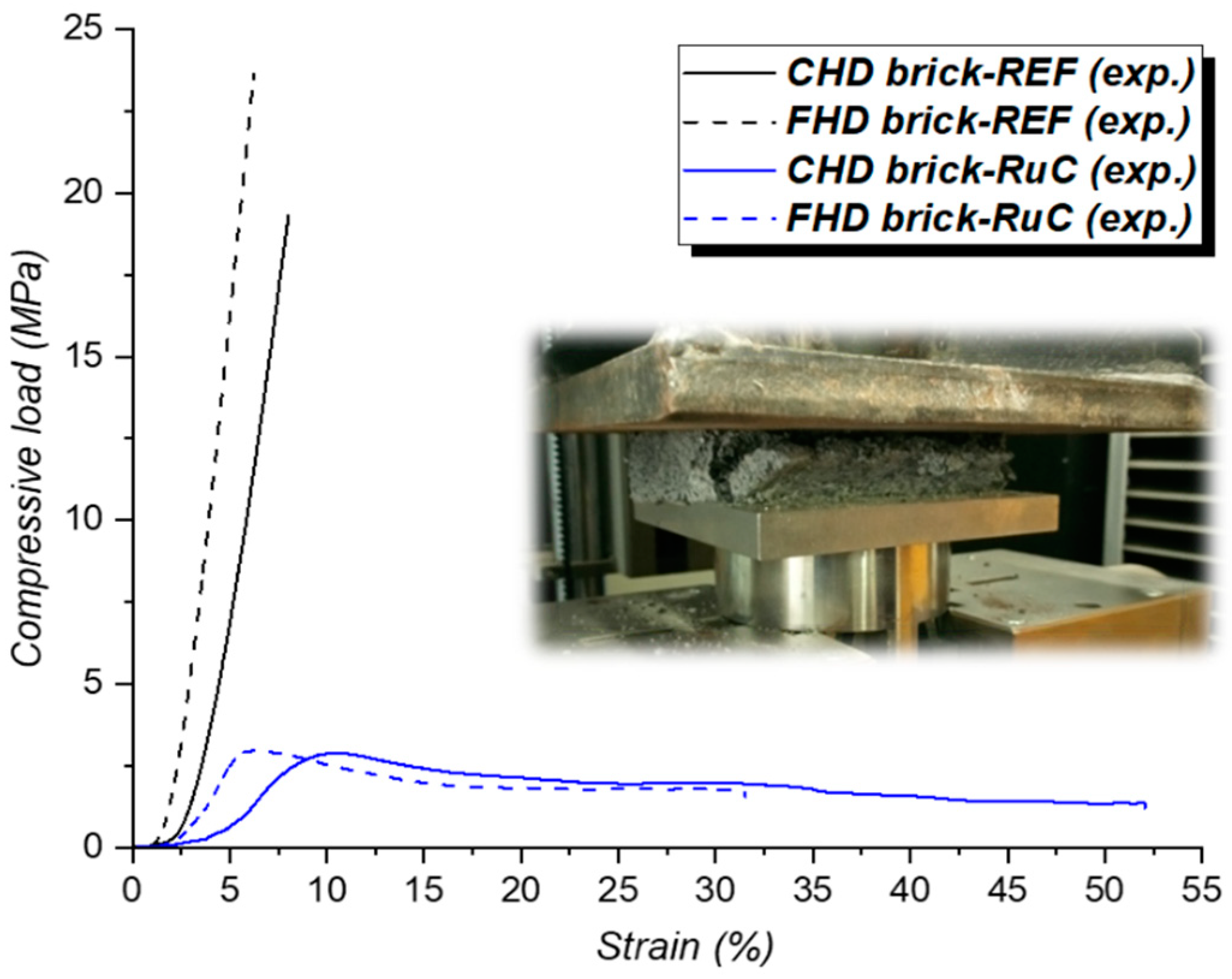
3.3. Experimental Mechanical Testing
- The FEA model considers the material as homogeneous, neglecting the composite nature of the cementitious formulations under study and, therefore, the contribution of mineral (sand) and polymeric (GWTR) aggregates on the mechanical behavior of the model, including interface interactions, stress distribution, deformation mechanisms induced by the different nature of the aggregates, etc.;
- Some fundamental input properties for the WW failure criterion (such as ν and σbc) were obtained indirectly from constitutive models and may not reflect the real mechanical behavior of the material;
- Dimensional variations between the digital model and real brick prototype due to the hygrometric shrinkage of the material, the geometric accuracy of the cavities, and surface roughness can inevitably affect the mechanical response of the samples.
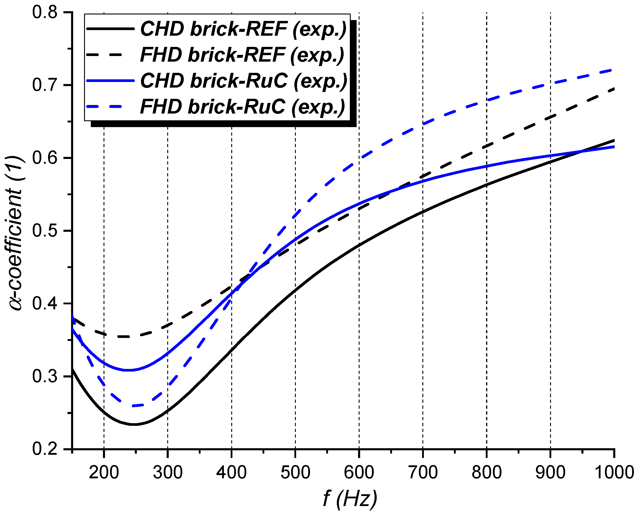
3.4. Experimental Acoustic Testing
4. Conclusions
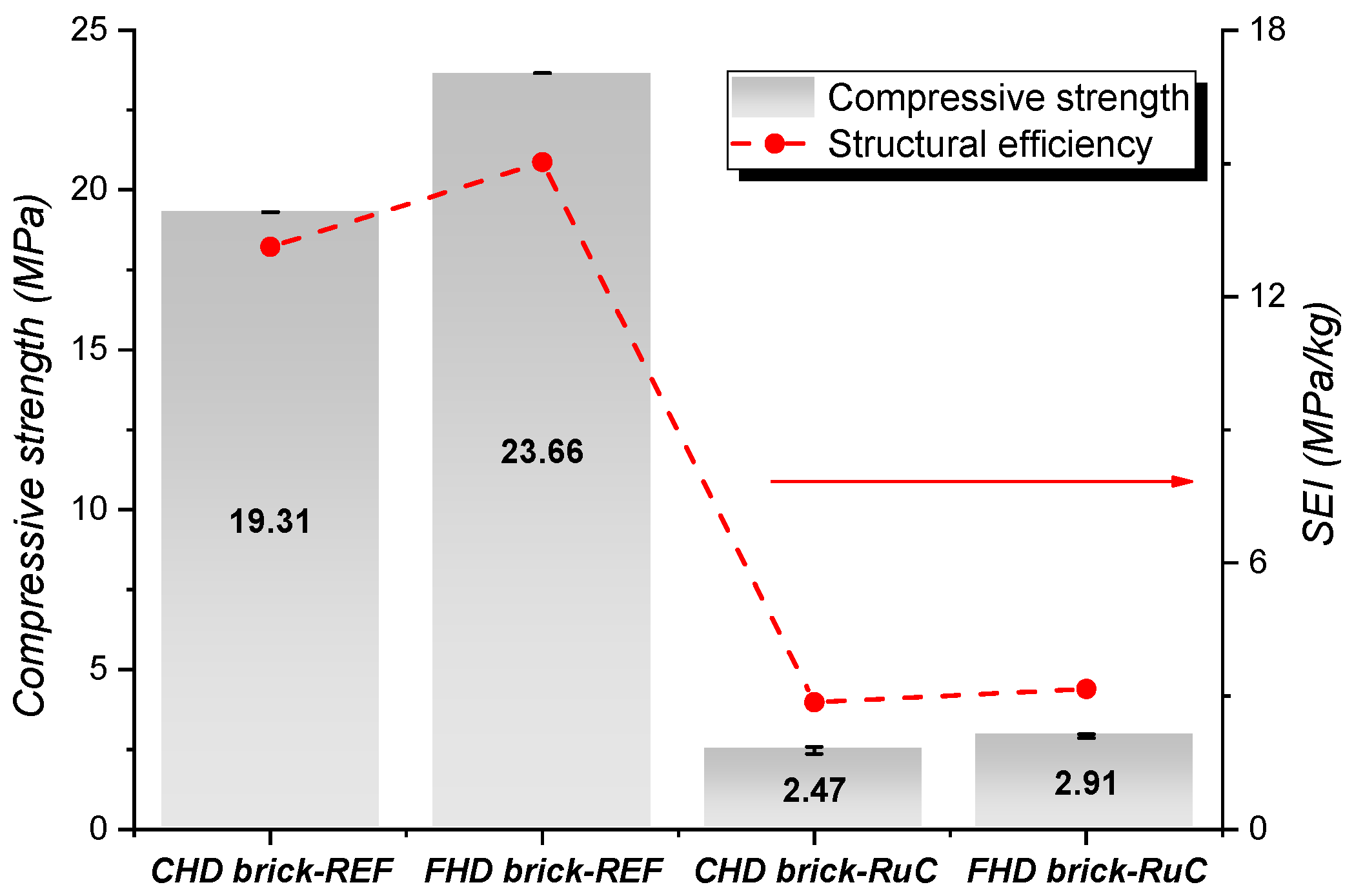
- Regardless of the concrete mix, the fractal hollow pattern provides a significant improvement in the engineering performance of the brick in terms of mechanical strength, structural efficiency, and acoustic absorption over 500 Hz. Considering the rubber–cement mix as a constituting brick’s material, an increase of 18% in compressive strength and 1000 Hz sound absorption coefficient can be achieved, moving from circular to fractal hole designs.
- Circular and fractal design bricks made up of ordinary concrete mix satisfy the minimum ASTM strength for load-bearing masonry units. A rubber–concrete mix involves a predictable loss in mechanical strength properties. However, the compressive strengths of rubberized blocks were very close to ASTM requirements for non-load-bearing applications.
- The samples investigated can be considered as “good” concrete sound absorbers. The rubber-functionalized cement mix yielded superior acoustic attenuation capacities compared to the reference material, regardless of the internal geometry of the brick, indicating the positive influence induced by the polymeric aggregates on the concrete’s sound-absorbing efficiency.
- From the numerical analysis by finite element method, the physical–acoustic parameters of the investigated rubberized mixes would seem to predict better attenuation performances to the brick, even at low frequencies, which are noise events of great interest in engineering field.
Author Contributions
Funding
Data Availability Statement
Acknowledgments
Conflicts of Interest
References
- Valentini, F.; Dorigato, A.; Rigotti, D.; Pegoretti, A. Evaluation of the role of devulcanized rubber on the thermomechanical properties of expanded ethylene-propylene diene monomers composites. Polym. Eng. Sci. 2021, 61, 767–779. [Google Scholar] [CrossRef]
- Shu, X.; Huang, B. Recycling of waste tire rubber in asphalt and portland cement concrete: An overview. Constr. Build. Mater. 2014, 67, 217–224. [Google Scholar] [CrossRef]
- Eldin, N.N.; Senouci, A.B. Engineering properties of rubberized concrete. Can. J. Civ. Eng. 1992, 19, 912–923. [Google Scholar] [CrossRef]
- Miller, N.M.; Tehrani, F.M. Mechanical properties of rubberized lightweight aggregate concrete. Constr. Build. Mater. 2017, 147, 264–271. [Google Scholar] [CrossRef]
- Turatsinze, A.; Garros, M. On the modulus of elasticity and strain capacity of self-compacting concrete incorporating rubber aggregates. Resour. Conserv. Recycl. 2008, 52, 1209–1215. [Google Scholar] [CrossRef]
- Ghizdăveț, Z.; Ștefan, B.M.; Nastac, D.; Vasile, O.; Bratu, M. Sound absorbing materials made by embedding crumb rubber waste in a concrete matrix. Constr. Build. Mater. 2016, 124, 755–763. [Google Scholar] [CrossRef]
- Zhang, B.; Poon, C.S. Sound insulation properties of rubberized lightweight aggregate concrete. J. Clean. Prod. 2018, 172, 3176–3185. [Google Scholar] [CrossRef]
- Guo, J.; Huang, M.; Huang, S.; Wang, S. An experimental study on mechanical and thermal insulation properties of rubberized concrete including its microstructure. Appl. Sci. 2019, 9, 2943. [Google Scholar] [CrossRef] [Green Version]
- Richardson, A.; Coventry, K.; Dave, U.; Pienaar, J. Freeze/thaw performance of concrete using granulated rubber crumb. J. Green Build. 2011, 6, 83–92. [Google Scholar] [CrossRef]
- Gerges, N.N.; Issa, C.A.; Fawaz, S.A. Rubber concrete: Mechanical and dynamical properties. Case Stud. Constr. Mater. 2018, 9, e00184. [Google Scholar] [CrossRef]
- Jie, X.U.; Yao, Z.; Yang, G.; Han, Q. Research on crumb rubber concrete: From a multi-scale review. Constr. Build. Mater. 2020, 232, 117282. [Google Scholar] [CrossRef]
- Thorat, P.K.; Papal, M.; Kacha, V.; Sarnobat, T.; Gaikwad, S. Hollow concrete blocks-A new trend. Int. J. Eng. Res. 2015, 5, 9–26. [Google Scholar]
- Turgut, P.; Yesilata, B. Physico-mechanical and thermal performances of newly developed rubber-added bricks. Energy Build. 2008, 40, 679–688. [Google Scholar] [CrossRef]
- Yüksek, İ.; Öztaş, S.K.; Tahtalı, G. The evaluation of fired clay brick production in terms of energy efficiency: A case study in Turkey. Energy Effic. 2020, 13, 1473–1483. [Google Scholar] [CrossRef]
- Mohammed, B.S.; Hossain, K.M.A.; Swee, J.T.E.; Wong, G.; Abdullahi, M. Properties of crumb rubber hollow concrete block. J. Clean. Prod. 2012, 23, 57–67. [Google Scholar] [CrossRef]
- Fraile-Garcia, E.; Ferreiro-Cabello, J.; Defez, B.; Peris-Fajanes, G. Acoustic Behavior of Hollow Blocks and Bricks Made of Concrete Doped with Waste-Tire Rubber. Materials 2016, 9, 962. [Google Scholar] [CrossRef] [Green Version]
- Al-Fakih, A.; Wahab, M.A.; Mohammed, B.S.; Liew, M.S.; Zawawi, N.A.W.A.; As’ ad, S. Experimental study on axial compressive behavior of rubberized interlocking masonry walls. J. Build. Eng. 2020, 29, 101107. [Google Scholar] [CrossRef]
- Lourenço, P.B.; Vasconcelos, G.; Medeiros, P.; Gouveia, J. Vertically perforated clay brick masonry for loadbearing and non-loadbearing masonry walls. Constr. Build. Mater. 2010, 24, 2317–2330. [Google Scholar] [CrossRef]
- Del Coz Díaz, J.J.; Nieto, P.G.; Rabanal, F.Á.; Martínez-Luengas, A.L. Design and shape optimization of a new type of hollow concrete masonry block using the finite element method. Eng. Struct. 2011, 33, 1–9. [Google Scholar] [CrossRef]
- Al-Tamimi, A.S.; Al-Osta, M.A.; Al-Amoudi, O.S.B.; Ben-Mansour, R. Effect of geometry of holes on heat transfer of concrete masonry bricks using numerical analysis. Arab. J. Sci. Eng. 2017, 42, 3733–3749. [Google Scholar] [CrossRef]
- Sassine, E.; Cherif, Y.; Dgheim, J.; Antczak, E. Investigation of the mechanical and thermal performances of concrete hollow blocks. SN Appl. Sci. 2020, 2, 1–17. [Google Scholar] [CrossRef]
- Valente, M.; Sambucci, M.; Sibai, A.; Musacchi, E. Multi-physics analysis for rubber-cement applications in building and architectural fields: A preliminary analysis. Sustainability 2020, 12, 5993. [Google Scholar] [CrossRef]
- Kim, H.; Hong, J.; Pyo, S. Acoustic characteristics of sound absorbable high performance concrete. Appl. Acoust. 2018, 138, 171–178. [Google Scholar] [CrossRef]
- Sapoval, B.; Haeberlé, O.; Russ, S. Acoustical properties of irregular and fractal cavities. J. Acoust. Soc. Am. 1997, 102, 2014–2019. [Google Scholar] [CrossRef]
- Hébert, B.; Sapoval, B.; Russ, S. Experimental study of a fractal acoustical cavity. J. Acoust. Soc. Am. 1999, 105, 1567–1574. [Google Scholar] [CrossRef]
- Godbold, O. Investigating Broadband Acoustic Absorption Using Rapid Manufacturing. Ph.D. Thesis, Loughborough University, Loughborough, UK, 2008. [Google Scholar]
- EN 1097-7; Tests for Mechanical and Physical Properties of Aggregates—Part 7: Determination of the Particle Density of Filler—Pycnometer Method. UNI Standards: Milan, Italy, 2008.
- DIN 51701; Testing of Solid Fuels; Sampling and Sample Preparation, Sample Preparation. DIN Standards: Berlin, Germany, 2007.
- Sambucci, M.; Valente, M.; Sibai, A.; Marini, D.; Quitadamo, A.; Musacchi, E. Rubber-Cement Composites for Additive Manufacturing: Physical, Mechanical and Thermo-Acoustic Characterization. In Proceedings of the Second RILEM International Conference on Concrete and Digital Fabrication, Eindhoven, The Netherlands, 6–9 July 2020; Springer: Cham, Switzerland, 2020; pp. 113–124. [Google Scholar] [CrossRef]
- Sambucci, M.; Valente, M. Influence of Waste Tire Rubber Particles Size on the Microstructural, Mechanical, and Acoustic Insulation Properties of 3D-Printable Cement Mortars. Civ. Eng. J. 2021, 7, 937–952. [Google Scholar] [CrossRef]
- Valente, M.; Sambucci, M.; Chougan, M.; Ghaffar, S.H. Reducing the emission of climate-altering substances in cementitious materials: A comparison between alkali-activated materials and Portland cement-based composites incorporating recycled tire rubber. J. Clean. Prod. 2022, 333, 130013. [Google Scholar] [CrossRef]
- ASTM D792; Standard Test Methods for Density and Specific Gravity (Relative Density) of Plastics by Displacement. ASTM International: West Conshohocken, PA, USA, 1958.
- ASTM C 1202; Standard Test. Method for Electrical Indication of Concrete’s Ability to Resist Chloride Ion Penetration. ASTM International: West Conshohocken, PA, USA, 2019.
- Ingard, K.U.; Dear, T.A. Measurement of acoustic flow resistance. J. Sound Vib. 1985, 103, 567–572. [Google Scholar] [CrossRef]
- Sambucci, M.; Valente, M. Ground Waste Tire Rubber as a Total Replacement of Natural Aggregates in Concrete Mixes: Application for Lightweight Paving Blocks. Materials 2021, 14, 7493. [Google Scholar] [CrossRef]
- Assaggaf, R.A.; Ali, M.R.; Al-Dulaijan, S.U.; Maslehuddin, M. Properties of concrete with untreated and treated crumb rubber–A review. J. Mater. Res. Technol. 2021, 11, 1753–1798. [Google Scholar] [CrossRef]
- Si, R.; Guo, S.; Dai, Q. Durability performance of rubberized mortar and concrete with NaOH-Solution treated rubber particles. Constr. Build. Mater. 2017, 153, 496–505. [Google Scholar] [CrossRef]
- Rezaifar, O.; Hasanzadeh, M.; Gholhaki, M. Concrete made with hybrid blends of crumb rubber and metakaolin: Optimization using Response Surface Method. Constr. Build. Mater. 2016, 123, 59–68. [Google Scholar] [CrossRef]
- Geethamma, V.G.; Asaletha, R.; Kalarikkal, N.; Thomas, S. Vibration and sound damping in polymers. Resonance 2014, 19, 821–833. [Google Scholar] [CrossRef]
- Sambucci, M.; Cecchini, F.; Nanni, F.; Pucacco, G.; Valente, M. Metamateriali fonoassorbenti sviluppati via 3D printing per interventi acustici nel settore automotive. Riv. Ital. Di Acust. 2020, 44, 1–23. [Google Scholar]
- EN 771-1; Specification for Masonry Units—Part 1: Clay Masonry Units. UNI Standards: Milan, Italy, 2015.
- Nagy, B.; Orosz, M. Optimized Thermal Performance Design of Filled Ceramic Masonry Blocks. AMM 2015, 797, 174–181. [Google Scholar] [CrossRef]
- EN 1996-1-1; Eurocode 6—Design of Masonry Structures—Part 1-1: General Rules for Reinforced and Unreinforced Masonry Structures. UNI Standards: Milan, Italy, 2013.
- Hejazi, M.; Soltani, Y. Parametric study of the effect of hollow spandrel (Konu) on structural behaviour of Persian brick masonry barrel vaults. Eng. Fail. Anal. 2020, 118, 104838. [Google Scholar] [CrossRef]
- Lourenço, P.B. Computations on historic masonry structures. Prog. Struct. Eng. Mater. 2002, 4, 301–319. [Google Scholar] [CrossRef]
- Kumar, P.; Srivastava, G. Effect of fire on in-plane and out-of-plane behavior of reinforced concrete frames with and without masonry infills. Constr. Build. Mater. 2018, 167, 82–95. [Google Scholar] [CrossRef]
- Sideris, K.K.; Manita, P.; Sideris, K. Estimation of ultimate modulus of elasticity and Poisson ratio of normal concrete. Cem. Concr. Compos. 2004, 26, 623–631. [Google Scholar] [CrossRef]
- ASTM C384-95; Standard Test Method for Impedance and Absorption of Acoustical Materials by the Impedance Tube Method. ASTM International: West Conshohocken, PA, USA, 1998.
- El-Khoja, A. Mechanical, Thermal and Acoustic Properties of Rubberised Concrete Incorporating Nano Silica. Ph.D. Thesis, University of Bradford, Bradford, UK, 2019. [Google Scholar]
- Nguyen-Van, V.; Wu, C.; Vogel, F.; Zhang, G.; Nguyen-Xuan, H.; Tran, P. Mechanical performance of fractal-like cementitious lightweight cellular structures: Numerical investigations. Compos. Struct. 2021, 269, 114050. [Google Scholar] [CrossRef]
- Khoshhesab, M.M.; Li, Y. Mechanical behavior of 3D printed biomimetic Koch fractal contact and interlocking. Extrem. Mech. Lett. 2018, 24, 58–65. [Google Scholar] [CrossRef]
- Cai, X.; Guo, Q.; Hu, G.; Yang, J. Ultrathin low-frequency sound absorbing panels based on coplanar spiral tubes or coplanar Helmholtz resonators. Appl. Phys. Lett. 2014, 105, 121901. [Google Scholar] [CrossRef] [Green Version]
- Cheng, Z.; Shi, Z. Vibration attenuation properties of periodic rubber concrete panels. Constr. Build. Mater. 2014, 50, 257–265. [Google Scholar] [CrossRef]
- Thakur, A.; Senthil, K.; Sharma, R.; Singh, A.P. Employment of crumb rubber tyre in concrete masonry bricks. Mater. Today Proc. 2020, 32, 553–559. [Google Scholar] [CrossRef]
- Xie, S.; Yang, S.; Yan, H.; Li, Z. Sound absorption performance of a conch-imitating cavity structure. Sci. Prog. 2022, 105, 00368504221075167. [Google Scholar] [CrossRef] [PubMed]
- ASTM C 90; Standard Specification for Load-Bearing Concrete Masonry Units. ASTM International: West Conshohocken, PA, USA, 2014.
- ASTM C129; Standard Specification for Nonloadbearing Concrete Masonry Units. ASTM International: West Conshohocken, PA, USA, 2017.
- Komatsu, T. Improvement of the Delany-Bazley and Miki models for fibrous sound-absorbing materials. Acoust. Sci. Technol. 2008, 29, 121–129. [Google Scholar] [CrossRef] [Green Version]
- Neithalath, N.; Marolf, A.; Weiss, J.; Olek, J. Modeling the influence of pore structure on the acoustic absorption of enhanced porosity concrete. J. Adv. Concr. Technol. 2005, 3, 29–40. [Google Scholar] [CrossRef] [Green Version]
- Kim, H.K.; Lee, H.K. Acoustic absorption modeling of porous concrete considering the gradation and shape of aggregates and void ratio. J. Sound Vib. 2010, 329, 866–879. [Google Scholar] [CrossRef]
- Fediuk, R.; Amran, M.; Vatin, N.; Vasilev, Y.; Lesovik, V.; Ozbakkaloglu, T. Acoustic Properties of Innovative Concretes: A Review. Materials 2021, 14, 398. [Google Scholar] [CrossRef]
- Bala, A.; Gupta, S. Thermal resistivity, sound absorption and vibration damping of concrete composite doped with waste tire Rubber: A review. Constr. Build. Mater. 2021, 299, 123939. [Google Scholar] [CrossRef]
- Tie, T.S.; Mo, K.H.; Putra, A.; Loo, S.C.; Alengaram, U.J.; Ling, T.C. Sound absorption performance of modified concrete: A review. J. Build. Eng. 2020, 30, 101219. [Google Scholar] [CrossRef]


| Research Work | Aim of the Study | Major Remarks |
|---|---|---|
| Del Coz Díaz et al. [19] | Topological optimization of twelve hollow concrete block units, varying the number and shape of inner recesses, with the aim of reducing the brick’s weight, keeping suitable structural properties. | A weight reduction close to 45% is obtained with respect to the classic concrete block, keeping comparable structural efficiency in terms of strength-to-weight ratio. |
| Al-Tamimi et al. [20] | Twenty-three brick designs with different hole arrangements and one solid model were studied for concrete material to reach the model with the optimum holes in terms of thermal-insulation efficiency. | Increasing the hollow ratio tends to decrease the heat transfer from outer to inner brick sides significantly. At the same hollow ratio, there was an effect of the shape of holes in reducing the thermal flow through the bricks: rectangular shapes were more thermo-effective than circular ones. |
| Sassine et al. [21] | Mechanical and thermal behaviors of ten concrete hollow-block configurations are simultaneously studied by varying the blocks’ internal shape, aiming at determining the optimal hollow-block design and providing the optimal compromise between thermal insulation and mechanical strength. | Longitudinal bulkheads improve the thermal resistance of the blocks and, thus, reduce the heat flux passing through the element. The mechanical behavior varies slightly between the investigated models in vertical compression, reducing the influence of this parameter in the selection of the best design. |
| Valente et al. [22] | Mechanical performance of three types of hollow-brick designs, circular, square, and hexagonal holes, were numerically analyzed to select the best configuration for rubber–concrete mixes. | Circular and hexagonal hole designs offer the best result in terms of compressive strength. The “honeycomb” geometries have remarkable thermal and acoustic functionality; therefore, they have more attractive requirements for building. |
| Aggregate | Density (kg/m3) | Water Absorption (%) |
|---|---|---|
| River sand | 2476 | 20.0 |
| GWTR | 1144 | 9.6 |
| Sample ID | Cement (kg/L) | Water (kg/L) | Sand (kg/L) | RP (kg/L) | RG (kg/L) | w/c Ratio |
|---|---|---|---|---|---|---|
| REF | 0.72 | 0.300 | 1.20 | / | / | 0.42 |
| RuC | 0.72 | 0.325 | / | 0.275 | 0.275 | 0.45 |
| Specimen Type | Number of Specimens per Test | Test |
|---|---|---|
| 1 cm3 cubes | 3 | Density |
| 1 cm3 cubes | 3 | Permeable porosity |
| 1.5 cm 1.5 cm 10 cm beams | 3 | Three-point flexural test |
| 1.5 cm 1.5 cm 3 cm prisms | 3 | Compressive test |
| 5 cm 5 cm 2.5 cm blocks | 1 | Acoustic flow resistivity |
| Sample ID | ρ (kg/m3) | Φ (%) | σt (MPa) | σc (MPa) | Ec (GPa) | Rf (N × s × m−4) |
| REF | 2186 (18) | 21.39 (0.25) | 11.06 (1.48) | 35.89 (7.71) | 1.62 (0.47) | 13,872 |
| RuC | 1281 (21) | 22.82 (0.37) | 1.65 (0.51) | 4.93 (0.57) | 0.24 (0.02) | 19,862 |
| Brick Model | Number of Holes | Hole Area (mm2) | Hole Concentration Ratio (%) |
|---|---|---|---|
| CHD | 11 | 490.625 | 28 |
| FHD | 10 | 425 | 23 |
| REF Concrete Mix | |||
| Property | Value | Property Group | Evaluation |
| Density | 2186 kg/m3 | Basic | Experimental |
| Porosity | 21.39% | Basic | Experimental |
| Elastic modulus | 1.62 GPa | Basic | Experimental |
| Poisson’s ratio (ν) | 0.32 | Basic | [47] |
| Compressive strength | 35.89 MPa | WW model | Experimental |
| Tensile strength | 11.06 MPa | WW model | Experimental |
| Biaxial compressive strength | 43.07 MPa | WW model | [44] |
| RuC Concrete Mix | |||
| Property | Value | Property Group | Evaluation |
| Density | 1281 kg/m3 | Basic | Experimental |
| Porosity | 22.82% | Basic | Experimental |
| Elastic modulus | 0.24 GPa | Basic | Experimental |
| Poisson’s ratio (ν) | 0.12 | Basic | [45] |
| Compressive strength | 4.93 MPa | WW model | Experimental |
| Tensile strength | 1.65 MPa | WW model | Experimental |
| Biaxial compressive strength | 5.92 MPa | WW model | [44] |
| REF Concrete Mix | |||
| Property | Value | Property Group | Evaluation |
| Density | 2186 kg/m3 | Basic | Experimental |
| Porosity | 21.39% | Basic | Experimental |
| Acoustic flow resistivity | m−4 | DB model | Experimental |
| RuC Concrete Mix | |||
| Property | Value | Property Group | Evaluation |
| Density | 1281 kg/m3 | Basic | Experimental |
| Porosity | 22.82% | Basic | Experimental |
| Acoustic flow resistivity | m−4 | DB model | Experimental |
| Cutter Type | Cutter Diameter | Cutting Depth | Spindle speed | Feed Rate |
|---|---|---|---|---|
| End mill | 3 mm | 2 mm | 5000 rpm | 30 mm/s |
Publisher’s Note: MDPI stays neutral with regard to jurisdictional claims in published maps and institutional affiliations. |
© 2022 by the authors. Licensee MDPI, Basel, Switzerland. This article is an open access article distributed under the terms and conditions of the Creative Commons Attribution (CC BY) license (https://creativecommons.org/licenses/by/4.0/).
Share and Cite
Sambucci, M.; Sibai, A.; Fattore, L.; Martufi, R.; Lucibello, S.; Valente, M. Finite Element Multi-Physics Analysis and Experimental Testing for Hollow Brick Solutions with Lightweight and Eco-Sustainable Cement Mix. J. Compos. Sci. 2022, 6, 107. https://doi.org/10.3390/jcs6040107
Sambucci M, Sibai A, Fattore L, Martufi R, Lucibello S, Valente M. Finite Element Multi-Physics Analysis and Experimental Testing for Hollow Brick Solutions with Lightweight and Eco-Sustainable Cement Mix. Journal of Composites Science. 2022; 6(4):107. https://doi.org/10.3390/jcs6040107
Chicago/Turabian StyleSambucci, Matteo, Abbas Sibai, Luciano Fattore, Riccardo Martufi, Sabrina Lucibello, and Marco Valente. 2022. "Finite Element Multi-Physics Analysis and Experimental Testing for Hollow Brick Solutions with Lightweight and Eco-Sustainable Cement Mix" Journal of Composites Science 6, no. 4: 107. https://doi.org/10.3390/jcs6040107