Article

A Quantitative Investigation of Dislocation Density in an Al Matrix Composite Produced by a Combination of Micro-/Macro-Rolling

1
Centre of Excellence for Advanced Materials Application, Slovak Academy of Sciences, Dubravska Cesta 9, 84511 Bratislava, Slovakia
2
Department of Materials Engineering, Isfahan University of Technology, Isfahan 8415683111, Iran
3
Faculty of Mechanical Engineering and Ship Technology, Gdansk University of Technology, Narutowicza 11/12, 80-233 Gdansk, Poland
4
Department of Innovation Engineering, University of Salento, Via per Arnesano, 73100 Lecce, Italy
*
Authors to whom correspondence should be addressed.
J. Compos. Sci. 2022, 6(7), 199; https://doi.org/10.3390/jcs6070199
Submission received: 8 June 2022 / Revised: 27 June 2022 / Accepted: 4 July 2022 / Published: 7 July 2022
(This article belongs to the Special Issue Feature Papers in Journal of Composites Science in 2022)

Abstract

:
An aluminum matrix composite with dispersed carbon nanotubes (CNTs) was produced via flake powder metallurgy using a micro-rolling process and vacuum hot pressing (VHP), followed by conventional rolling using a macro-rolling process. The microstructure and mechanical properties of the produced composites were studied. In addition, a new quantitative model was introduced to study the dislocation density based on the microstructural parameters. The results revealed that the distribution characteristics of the CNTs in the Al matrix and the Al-CNT interfaces were the two main governing parameters of dislocation density. Moreover, the dependence of dislocation density on the geometry of the grains and crystallographic texture was shown in this model. The microstructural evolution revealed that a lamellar grain structure had been achieved, with a high capacity for the storage of dislocation. A uniform distribution of CNTs with high bonding quality was also seen in the final microstructure.

1. Introduction

To date, it has been a long-standing goal of materials scientists to fabricate aluminum matrix composites (AMCs) combining high strength and high ductility, but the properties of strength and ductility are mutually exclusive in most materials [1,2,3]. AMCs usually exhibit high strength, but their ductility and work hardening are limited, since dislocation activities are suppressed by the tiny grains. The strengthening and the loss of ductility in carbon nanotube (CNT)/Al composites are mainly caused by the grain refinement of the Al matrix resulting from the dispersion of CNTs and low dislocation storage capacity, respectively [4,5,6,7,8].
As an effective way of improving material properties, especially mechanical strength and ductility, severe plastic deformation techniques have been proposed [6,9,10,11,12]. Powder metallurgy (PM) by means of low-speed ball milling (LSBM) has been reported as a beneficial approach for preparing CNT/Al with CNT dispersion with a high level of uniformity by means of changing the spherical ductile metal powders into flake-shaped building blocks (the flake PM approach) [5,6,13,14,15]. During the cold-welding stage, the flaky powders are cold-welded into a lamellar structure, and the CNTs are introduced into the ductile powders. From a technical point of view, this powder processing can be referred to as micro-rolling, for the reasons given in our previous papers [13,16]. There is an increasing trend of utilizing the combined processes of ball milling powders followed by secondary plastic deformation [17,18,19,20], resulting in improved dispersion, a high level of the CNTs alignment, small degree of structural damage, and strong interfacial bonding. Chen et al. [19,21] studied the effect of performing post-sintering processing via hot extrusion on the strength of the bonding between Al powder particles and the dispersion uniformity of the CNTs in the Al matrix. The simultaneous improvement of Al–Al grains and CNT–Al interfacial bonding by hot extrusion made it possible to avoid the traditional trade-off between strength and ductility. Therefore, a smart and practical technique for achieving PM via a micro-/macro-rolling (MMR) process was performed here in order to perform a quantitative investigation of the dislocation density capability of CNT reinforcing Al bulk composite with an ultrafine-grained (UFGed) microstructure. In fact, PM technology, especially flake PM, is regarded as being a high-efficiency method of mass production, and is able to disperse reinforcement additives homogeneously in the Al matrix and balance the strength and ductility of the composites. In addition, by considering a number of innovative flake PM technologies, such as macro-/micro-rolling [13,16], shift ball milling speed [5,14], etc. [4,17,20,21], other advantages of FPM such as the development of approaches that are feasible and cost-effective, are attainable.
Dislocations, as the first and most important structural component, are the result of unprecedented differences in the mechanical properties of metal matrix composites (MMCs), especially AMCs. These differences can be attributed to: (1) differences in the dislocation storage capabilities of the microstructural components; and (2) additional strain hardening capacity. Hence, there is an urgent need to obtain an in-depth understanding of the evolution of dislocation density during the fabrication process. Such an understanding could be effective in developing the knowledge needed to overcome the trade-off between strength and ductility and to tailor high-performance AMCs. At the nano and meso levels, the plastic deformation of metals occurs as a result of the formation, movement, and storage of dislocations [22,23]. When a material undergoes plastic deformation, the structure can change at the meso, micro and nano levels, especially when subjected to extremely large plastic deformations [5,13,15,24]. The stored dislocations are distributed into fairly regular microstructures with characteristics that depend on the process and material parameters. As a matter of fact, all of these changes are possible as a result of the formation and evolution of structural defects, especially dislocations. Therefore, it is vital to quantitatively determine the dislocation density distributions and evolutions as functions of induced strains. Relevant research [22,25,26] has been performed, focusing on the numerous constituents undergoing strain during macro processing, and so far, only a few studies have been performed focusing on the evolution of dislocation density during powder processing [5,27,28,29].
Along this line of research, the present study uses a CNT/Al composite as a case study to quantify the dislocation density resulting from the accumulation of intense strain imposed during the MMR process. As a matter of fact, we aim at obtaining a precise understanding of the correlation between dislocation density and microstructure and mechanical properties. From this point of view, the quantitative exploration of dislocation density during a combination of powder-processing and powder-bulk-processing is the first aim of this paper. In addition, the correlation between microstructural components and dislocation density will then be discussed in light of the experimental results.

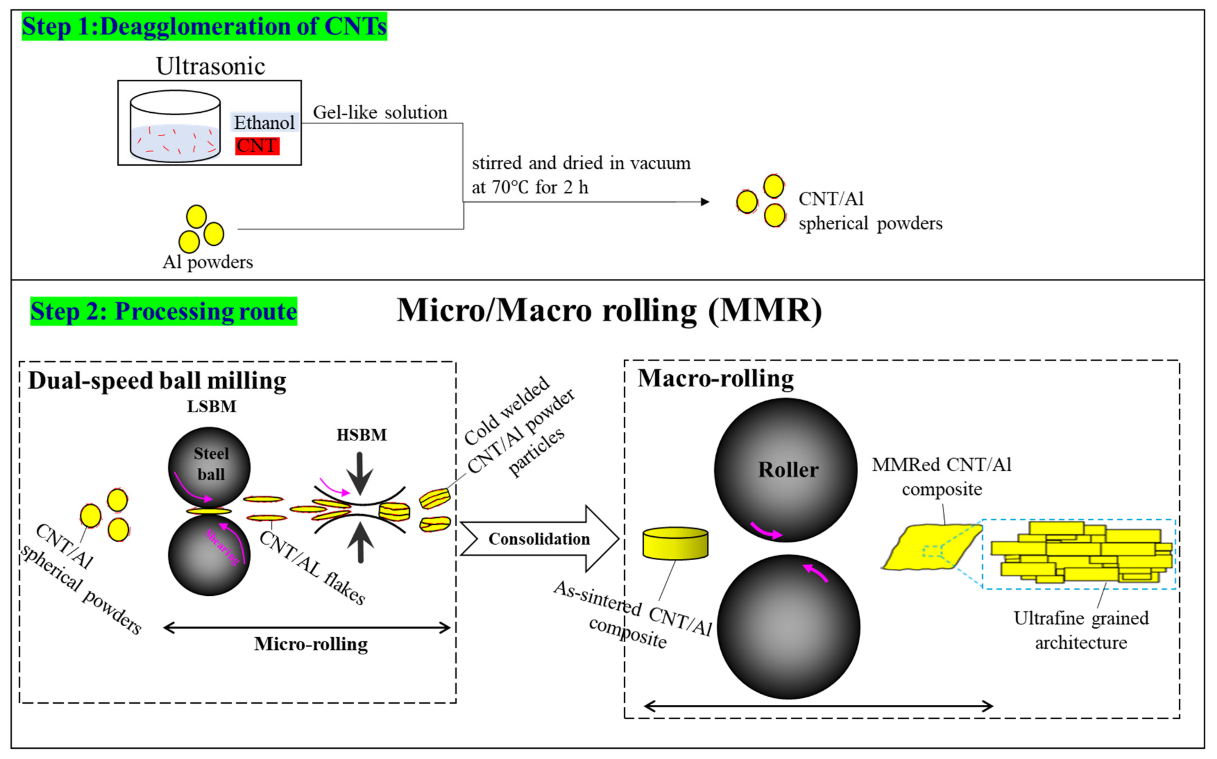
2. Materials and Methods

The as-atomized Al powders with an average diameter of ∼17 µm (d90 = 17 µm), in addition to 1 and 1.5 wt% of CNT (~1–2 μm in length and ~15 nm outer diameter, aspect ratio ~130) reinforcement was used as the raw materials. An ultrasonic shaker with ethanol as a solvent was used to ensure the breaking of CNTs clusters. The Al powder was then added to the solvent and dried in vacuum atmosphere at 70 °C. The powder mixture was then ball milled for 9 h at 120 rpm (low speed ball milling: LSBM) and for 1 h at 360 rpm (high speed ball milling (HSBM)) to achieve a final flake shape of the primary powder, and then, was pressed into cylindrical billets suing a graphite mold using a vacuum pressing machine. The as-pressed billets were hot extruded at 500 °C into bars with an extrusion ratio of 25:1. The produced samples were then rolled at 150 °C to 20, 45, and 90% reduction in thickness. Figure 1 reveals a schematic illustration of the processes used for the fabrication of the final composite; however, more details of the process can be fined elsewhere [6,13].
In order to characterize the morphologies of grains and reinforcements, a high-resolution transmission electron microscope (HR-TEM, FEI Talos F200×, Thermo Fisher Scientific, Waltham, Massachusetts) at a working voltage of 200 kV was applied. EBSD (electron backscattered diffraction) analyses were carried out at a step size of 0.1 mm by means of a JEOL JSM-7001F SEM (Tokyo, Japan) with a field emission gun operating at 15 kV using a program TSL OIM Data Collection ver. 6, where the step size in 0.1 µm depending on the size of structure and scanned area. To characterize the initial microstructures, samples were polished via standard metallographic techniques. Mechanical properties of the produced composites were examined using tensile and hardness tests. The tensile test specimens were cut from the rolled composites according to the ASTM E8M standard, along the rolling direction (RD) at a constant strain rate 0.5 mm/min using Instron 5848 tester. Vickers hardness (HV) test was performed on the produced composites on the rolling direction—normal direction (RD-ND) plane, under 50 g load for 10 s.

3. Results and Discussion

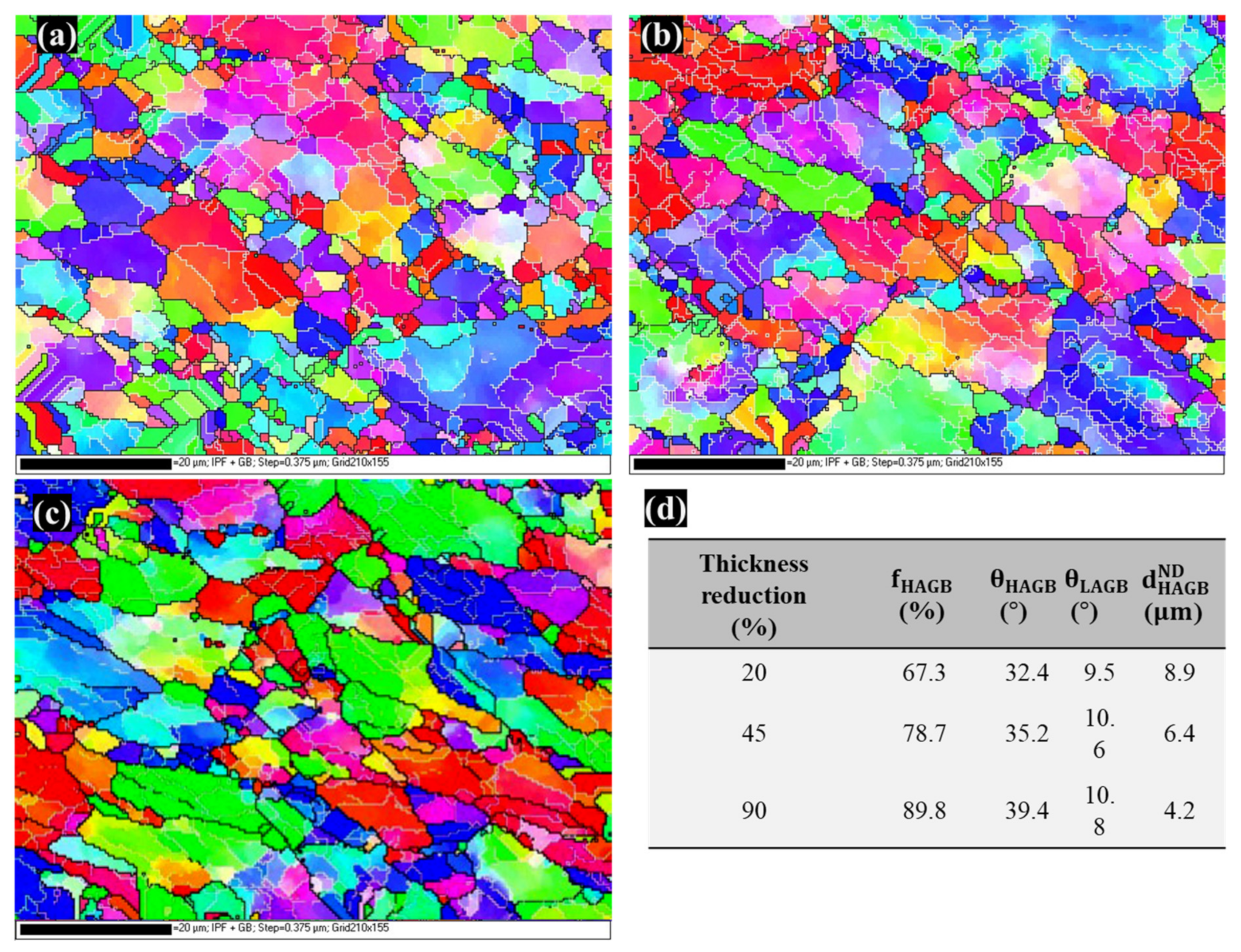
3.1. Microstructure and Mechanical Properties

The inverse pole figure (IPF) maps of the Al/CNT composites in the presence of the 1 wt% of CNT as a function of the thickness reduction during macro-rolling is shown in Figure 2 Microstructure of the 20% rolled sample (Figure 2a) reveals a homogeneous grain distribution in which grains are mostly equiaxed. The effect of increase in the strain amount is obvious after 45% thickness reduction, where the grains elongated along the RD (Figure 2b). Further rolling of the composite to 90% reduction in thickness also results in an elongated microstructure as revealed in Figure 2c. Generally, formation of the elongated microstructure during rolling has been widely reported in different materials [30,31,32]. Formation of elongated grains can increase the volume fraction of the grain boundaries (GBs) and also leads to the more uniform distribution of the reinforcement particles in the composite structure [31,33]. In addition, it has been shown that in elongated microstructure not only the density of dislocations increases due the enhancement of strain during rolling but also the dislocation-dislocation and dislocation-grain boundary interactions increase significantly due to the lamellar structure of the grains [6,13]. These phenomena can strongly affect the hardening behavior and consequently the mechanical properties of the produced composites.
Color variation within the elongated grains implies that minor misorientation has accumulated within the grains. As the strain increased, the misorientations angle of these boundaries also increase, which are more likely to result in the formation of new smaller grains with high angle boundaries. For comparison purposes, Figure 2d is depicted with parameters such as the average GB misorientation angle, the fraction of HAGBs and HAGB spacing in normal direction ( d HAB ND ). Indeed, the d HAGB ND values are considered as the average grain size values of the Al/CNT composite as given in Figure 2d. As the thickness reduction increases, the average grain size, namely d HAGB ND decreases, indicating the grain refining of the Al grains. With the decrease in grain size the ratio of the HAGBs increases and grain boundaries do impede dislocation motion and increase the strength. Precisely, this behavior is rationalized by limited dislocation ability and dislocation-dislocation interactions within refined grain interiors, whereas free dislocations path is restricted mostly by a large surface area of HAGB resulting in enhancing the strength and ductility simultaneously. Obviously, there is a significant difference in the distributions of the misorientation angles and HAGB fraction between samples processed by the different thickness reductions. Both the average misorientation angle and HAGB fraction increases as accumulated strain increases, whereas the HAGB spacing decreases. The former can be attributed to increase dislocation density and developing non-equilibrium GBs such as geometrically necessary boundaries (GNBs) and incidental dislocation boundaries (IDBs), while latter can be related to both triple junction motion during recovery and continuous recrystallization (CDRX) [34,35].
Variation in hardness of the produced composites with 1 and 1.5 wt.% of CNT is plotted in Figure 3 as a function of the thickness reduction. It can be seen that the hardness of both the composites increased sharply with increase in thickness reduction. Additionally, the hardness of the composite with 1.5 wt.% of the CNT was higher at different amount of the strain.
Microstructure of rolled composites revealed the formation of new grain boundaries with higher misorientation and also a complex network of grain boundaries with misorientation less than 15° (see Figure 2). It is well-know that with increase in grain boundary portion in the microstructure, grain boundary strengthening takes place as a result of atomic mismatch, and therefore, the hardness of the composite increases. Additionally, increment of dislocation density during rolling leads to increase in hardness.
In addition, it has been revealed that, CNTs are mostly located at grain boundaries and also distributed in the grain interiors in the composites which can lock the grain boundaries and hindering of dislocations movements [29,36]. Increase in CNTs amount in the composite can intensify this phenomenon, and consequently, higher hardness of the composite. Moreover, an increase in CNTs amount led to decrease in distance between the particles, and therefore higher amount of energy is needed for dislocation movements (which means higher hardness).
Pole figures of the composites at different stages of deformation are presented in Figure 4. First thing to be considered is that the intensity of the texture is low in all of the samples. In addition, it can be seen that texture components such as {100} <110> and {001} <100> intensify with increase in strain amount. It is well known that, <110> is the major direction of shear texture in FCC materials and formation of components along this direction has been widely reported during rolling of Al [37,38,39]. Formation of shear bands during rolling of Al was proposed as the main reason of shear texture components such as {100} <110>. However, high temperature of rolling (150 °C) leads to the formation of reduced number of shear bands, and therefore, the intensity of the shear texture increases in a low rate [37]. Additionally, development of {001} <100> texture component during recrystallization of high stacking fault energy (SFE) materials such as aluminum have been reported [40]. It is now accepted that the origins of the cube grains on recrystallization after high-temperature deformation are the cube-oriented elements of the deformed structure [35].
In the following, tensile properties of the Al/1 wt% CNT composite is only studied, to clarify the evolution of dislocation density as imposed strain caused by rolling process increases. Figure 5 depicts the engineering tensile stress–strain curves and strain hardening rate curves of CNT/Al composites, and the data were listed in Table 1 as insert in Figure 1. Obviously, as thickness reduction increases, tensile properties and the strain hardening capability enhances. The yield strength ( σ YS ), tensile strength ( σ UTS ), uniform elongation ( ε u ) and total elongation ( ε t ) of the composite were 240 MPa, 356 MPa, 4.5 and 13.41 at 20% of thickness reduction, whereas after 90% of thickness reduction thses values increases to 302 MPa, 468 MPa, 5.87, and 15.7, respectively. In other words, as induced strain increases by applying further thickness reduction the σ YS , σ UTS , ε u , and ε t increase about 25%, 32%, 30%, and 17%, respectively. These results are also superior to the published mechanical data with 2.3 to 10 vol% of ceramic particles [3,41,42,43,44,45,46,47]. The Al/CNT composite fabricated by micro/macro rolling process has more pronounced mechanical properties when compared with other MMCs fabricated by the combination of various PM routes with different consolidation techniques. The UTS values of Al/1 wt.% CNT composite after 90% of thickness reduction were about 2.6 time of the UTS of Al/15 vol.% B4C composites fabricated by wet attrition milling and hot extrusion [47], and about 2.15 time of the UTS value of bimodal sized Al/10 vol.% Al2O3 composites fabricated by spark plasma sintering [3,41]. Irrespective of the architecture design tailored by MMR process, it can be reported that the MMR process not only improve the strain hardening thanks to providing more space in elongated Al grains anchored by CNTs to store more dislocations, but also increases both uniform and total elongation (about 2 times with [3], and 0.2 times with [4]).
The strain hardening rate has a close correlation to dislocation density, as it increases as dislocation density increases during inducing severe plastic deformation process. As shown in Figure 5b, the composite processed to 90% thickness reduction represents a larger strain hardening rate than the one processed to 45% and 20% thickness reduction, respectively. This is due to evolution of dislocation density both in grain interior and grain boundary affected zone (GBAZ) regions [7,15,48,49]. As a matter of fact, a high density of GNDs near the Al/CNT interface can be induced due to the significant strain incompatibility [5,7,50,51]. The strengthening mechanism of coarse grain and fine grain composite materials mainly contained the GB strengthening (mostly caused by HAGBs and LAGBs), dislocation strengthening (mostly resulted from individual dislocations inside the Al grain interior), Orowan strengthening (mostly caused by the interaction between mobile dislocations and CNTs), load transfer strengthening (mostly is can be estimated by the shear lag model [7,15], and CNT strengthening (mostly due to accommodating of GNDs by the near-interface strain gradients during deformation, which provide back stress upon mobile dislocation, resulting in higher flow stress [3,29,44]). The experimental results demonstrated that, by applying cumulated strain caused by cold rolling, the strength of Al/CNT composites (both σ YS and σ UTS ) was significantly increased. This more likely attributed to grain refinement, the geometrically necessary dislocations (GNDs) caused by thermal mismatch between the matrix and reinforcement, Orowan strengthening and load transfer mechanism. In what follows, a model based on the correlation between imposed strain and dislocation density is proposed to address the strength contribution from involved mechanisms is evaluated quantitatively.

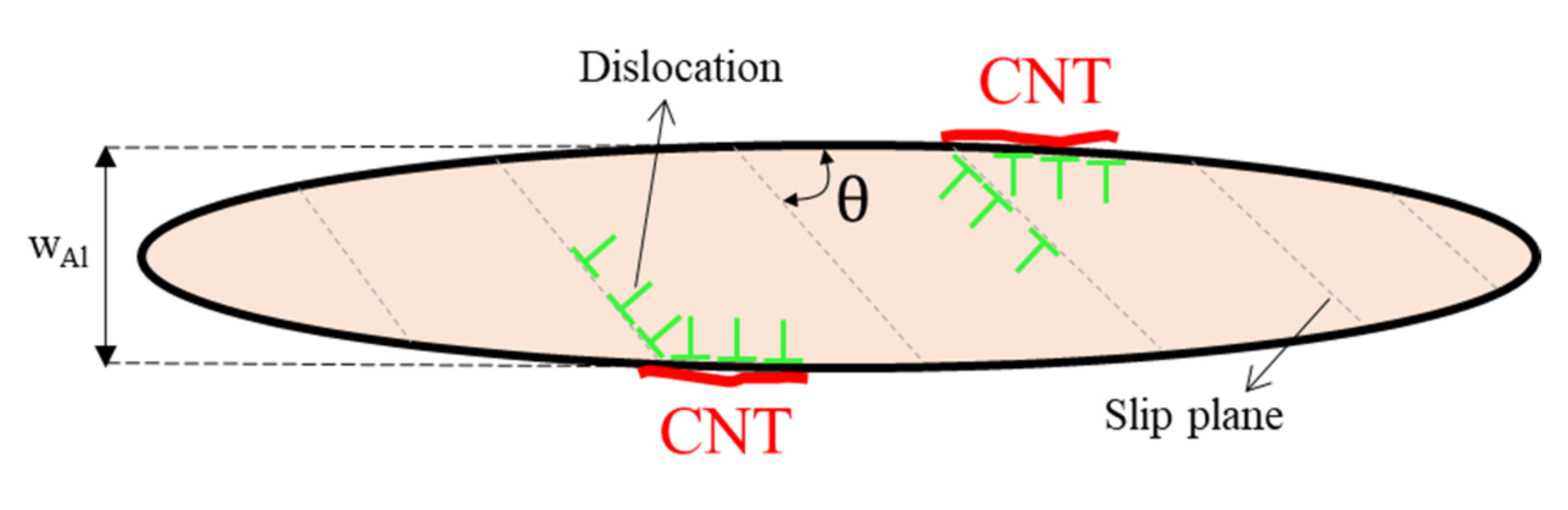
3.2. Deformation Model

Generally, the flow stress of ultrafine-grained pure metals consists of friction stress ( σ 0 ~ 1.6 MPa [52]), grain boundary strengthening ( σ GB ), dislocation strengthening ( σ dis ), dispersion strengthening (Orowan mechanism, σ Ow ), and load transfer ( σ L ).
Due to a large aspect ratio of CNTs (about 150 in our case) load transfer becomes the dominant strengthening mechanism, whereas the Orowan strengthening mechanism plays only a secondary or even minor role in strength contribution [6,53]. Considering shear-lag theory [54], σ L can be calculated as follows [6,27]:
σ L = VS σ m 2 cos 2 θ
where V and S are volume fraction and aspect ratio of CNTs, σ m is matrix strength ( ~ 178 MPa [6]), and θ is the angle between CNTs and extrusion direction of samples and typically is 45 ° .
Assuming the aspect ratio of CNT undergoes no change during the rolling process and using the values given for the involved parameters in load transfer strengthening, σ L value for Al/1 wt% CNT is independent of imposed strain, estimated to be ~ 56 MPa over all imposed thickness reduction values.
The Orowan strengthening mechanism can be resulted from CNTs, and the following equation can be used [55]:
σ Ow = M   0.4 μ Al b π 1 ϑ Al   ( ln d ¯ R b λ R )
where μ Al , ϑ Al , and d ¯ R are the shear modulus (25.4 GPa) and Poisson’s ratio (0.33) of Al and the equivalent diameter of intragranular reinforcement, respectively. λ R is the mean distance between the reinforcements, where
λ R = d ¯ R   ( π 4 V 1 )
d ¯ R as an equivalent diameter for rod-shaped CNTs should be used to calculated by the following equation as express:
d ¯ R = D . 3 S 2 3
where D and S are the diameter and aspect ratio of CNTs.
To estimate the dislocation strengthening, it is indispensable to calculate dislocation density which basically depends on the imposed strain. In the line of our previous paper [13], the overall amount of strain induced to the produced composite can be considered as the sum of the strain during the flake powder metallurgy (micro-rolling, εmicro) and the strain applied during rolling process (macro-rolling, εmacro). Therefore, the total amount of strain (εt) can be defined as follows:
ε t = ε micro + ε macro
A detailed achieving ε micro and ε macro under micro/macro rolling was published previously [13]. For this reason, only equations representing ε micro and ε macro and the total strain are introduced. Generally, five different stages are introduced during powder evolution in ball milling [56]. In the first stage, the repetitive collisions and plastic deformation leads to a particle flattering and the spherical-shape particles changes to flake-shape particles. During milling the required time to deform the particles form a spherical-shape to a flattened flake- shape particles is proportional to the time between different ball collisions. In addition, it is well-known that the hardness of the powders during milling is can strongly affect the applied strain to the powders. It was revealed by Maurice et al. [57] that the hardness of powder during milling ( H p V ) can be calculated by:
H p V = H 0 V + 3 K ε n
where H 0 V is the hardness of the initial powder, K is the strength coefficient, and n is the work-hardening exponent of the powder.
Considering all of the factors affecting the induced strain during micro rolling process, the total strain imposed to powder during this process is as follow:
ε micro   =   ln { 1 ϑ B R B h ρ B H v V 1 / 2 }   ×   1 45 π   (   t   H p V 1 / 2 ρ B 1 / 2 h   ϑ B )   ×   f Al
where ϑ B , R B , ρ B are the balls speed (m/s), R B is the ball radius, the balls density, and H v V is the vital Vickers hardness. h = 2 d p [58] where d p is the mean diameter of the as-received powder. f Al and t are the volume fraction of aluminum particles and the time of the milling, respectively.
The amount of the strain imposed to the samples during the macro-rolling process can be calculated using following equation:
ε macro = h 0 h f h 0   =   { 1 R 1 }
where h 0 and h f are the original thickness and final thickness of the specimens, respectively. R is the ratio of the original transverse length to the final short transverse length.
Eventually, the total amount of strain imposed to the samples during the micro-macro-rolling (MMR) can be calculated using:
ε t = ln { 1 ϑ B R B h ρ B H v V 1 / 2 }   ×   1 45 π   (   t   H p V 1 / 2 ρ B 1 / 2 h   ϑ B )   ×   f Al   + 1 R 1
In order to calculate the dislocation density in this model the main focus will be on the strengthening resulted from the evolution of dislocation during plastic deformation. Then, the effect of the plastic strain imposed during MMR process on the shape, size and crystallography texture parameters of the matrix will be considered based on their effect on dislocation density. The total density of dislocation is considered as the sum of the dislocations generate during the micro-rolling and macro-rolling.
ρ MMR = ρ micro rolling + ρ macro rolling
In order to calculate the density of dislocations formed during the micro-rolling process the generation of the dislocations in grain boundaries and grain interior should be considered. Most of the dislocations stored in grain interior and LAGBs. Based on previous results [59,60,61,62], the LAGBs with misorientation angle below 3° acted as dislocation strengthening and the rest of the GBs were regarded as GB strengthening. Therefore, to probe the contribution of dislocation strengthening, it is necessary to pay attention to both individual dislocations in the GIs, and the dislocations arranged in LAGBs with miorientation angle less than the critical angle ( θ c = 3 ° ). Density of dislocations during the deformation inside the GI (ρGI) in the UFGs of the composite, is governed by following parameters: (1) dislocation-dislocation pinning, (2) dislocations annihilation due to the dynamic recovery, and (3) term -keρSSD, which is related to the dynamic recovery of additional dislocations at GBs due to decrease in grain size [63,64]. Density of dislocations for a given strain during the deformation, can be calculated using following equations which was in line the previous papers [7,13,15].
d ρ GI d ε micro rolling = d ρ + GI d ε micro rolling + d ρ GI d ε micro rolling
The ρ GI is the density of dislocations of the GI which can be expressed:
ρ GI = M ε micro bw Al / cos θ
where wAl is the width of the lamellar Al UFGs, θ is the average angle between the slip direction and the tensile direction, which is assumed to be almost 45° as illustrated in Figure 6.
Dislocation density is significantly affected by the decrease in grain size and the change in the aspect ratio. Therefore, the effective grain size is defined for the HAGBs spacing in normal direction ( d HAGB ND ). Therefore, Equation (12) can be re-written as follow:
ρ GI = M × ε micro × cos θ × S micro rolling bd HAGB ND
In Equation (13), the S micro rolling is aspect ratio of the lamellar Al grains after micro-rolling process. As mentioned previously, during micro-rolling process the imposed plastic deformation resulted in the flattening of powder particles and the kinetic energy of balls is transferred to the powder particles. Additionally, texture evolution is not occurred as the imposed deformation is continuously changing the stress direction and deformation mode for each particle. However, the plastic deformation imposed during the macro-rolling process, can lead to the formation of the crystallographic texture. Moreover, mostly in the FCC materials, crystallographic texture affects the density and distribution of dislocations which depends on the grains with respect to the stress axis [65].
Therefore, the influences crystallographic texture parameter on the density of dislocations during the macro-rolling process should be considered. To this end, the percentage of hkl RD oriented grains along rolling direction, PO hkl , are calculated as follow:
PO hkl = I hkl I hkl × 100
In the Equation (14), I hkl is the sum of the Bragg reflections intensity of each (hkl). Usually, {001} <110> texture forms as the rolling led to shear deformation in the Al. Hence, it seems that the rolling direction is consistent with the direction of <110> which is the major direction of shear texture in FCC materials. Moreover, in this work, (hkl) represents three most intensive Brag reflection crystal faces (111), (200) and (220), respectively. During plastic deformation in macro-rolling process the density of the dislocations can be expressed by:
ρ macro rolling = M ε macro rolling b λ
where M is the Taylor factor ( ~ 3.06) and λ is the average glide distance of the dislocations.
Since the distance between the center and edge of the lamellar UFGs is the minimum distance for gliding of the dislocations, it is hence logical to assume that the short transverse length of matrix grain is equal to the average glide distance of the dislocations. Therefore, it can be expressed by Equation (16).
λ = w Al   cos θ
Consequently, the dislocation density is given as follow:
ρ macro rolling = 1     R 1 × M × cos θ b × w Al × PO hkl
By and large, the overall density of dislocation resulted from plastic deformation imposed during MMR process can be calculated through:
ρ MMR = ρ 0 + 3   f θ < 3 °   θ θ < 3 ° bd HAGB ND + M × ε micro × cos θ × S micro rolling bd HAGB ND + { 1     R 1 × M × cos θ b × w Al × PO hkl }
All parameters used in the proposed model are listed in our previous papers [5,7,13,15]. The total imposed strain and dislocation density calculated by the proposed equations are given in Table 1.
Different orientations in the grains leads to the formation of domains inside the grains and are significantly affected by the strain applied by micro-rolling process. The average of misorientation inside an Al/CNT particle could be between the misorientation of a low angle grain boundary (LAGB) to a high angle grain boundary (HAGB). During the milling process, formation of new dislocations led to increase in the LAGBs in the primary stages, and then, by increase in milling time the LAGBs decreases due to the rearrangement of dislocations as a result of dynamic recovery [29,37,66]. It worth mentioning that, the extension of the LAGBs in the Al alloys remains almost the same at strain larger than 1–2 [67]. There are many HAGBs inside grains that did not continue to form a circle as a new grain, but banded the interior of the grain to form regions of different orientations. Therefore, the density of the LAGBs and HAGBs increases at the same time by increasing the milling time. The former is arisen from the large changes in orientation inside the lamellar grains and latter is originated from the gradual increasing of the misorientation in subgrain boundaries as a result of the dislocations density enhancement.
In addition, since MMR process typically provide an elongated UFG microstructure in longitudinal direction [5,6,13,14,15], therefore, the geometry effect should to be take into account in the calculation. To this end, influences of geometry of deformation on the density of HAGBs is studied by Razavi et al. [68] and a technique is proposed to calculate this effect. This technique can be similarly used to show the effect of the geometry on the density of the LAGBs. Therefore, HKL software is used to measure the average aspect ratio of the grains both with LAGBs (Equation (20)) and HAGBs (Equation (21)).
G HAGB = 1 + S HAGB 2 S HAGB
G LAGB = 1 + S LAGB 2 S LAGB
where S LAGB and S HAGB are the average aspect ratio of the subgrains and grains with LAGBs and HAGBs, respectively. The calculated value of S LAGB and S HAGB based on EBSD images are given in Table 2.
It is well known that the microstructures severely deformed of the metallic materials usually exhibit elongated grains, high density of dislocations and a high fraction of LAGBs [11,12]. The ascending trend of dislocation density as a function of imposed strain can be logical, whereas the descending trend of LAGBs should be justified. Since in the current study, the LAGBs with misorientation angle below 3° acted as dislocation strengthening and the rest of the GBs were regarded as GB strengthening. Therefore, it is logical to express that the portion of LAGBs excluded from the total fraction of LAGBs and considered as individual dislocations. In addition, one can be stated that high-stacking energy materials (herein Al) have high rate of recovery which in turn transforms LAGBs into HAGBs. It is known that most of the dislocations stored in grain interior and LAGBs. What’s more, the elongated grains with higher aspect ratios in Al/CNT composite evidence higher dislocation storage capabilities than the equiaxed ones and thus benefit the tensile properties in according to the results [7,9].
Hence, the role of contribution of GBs and dislocation in strengthening by taking into account the GB character in the increment of the density of dislocations during MMR process, can be expressed using following equation:
σ GB = σ LAB + σ HAB = G LAB K HP f 3 ° < θ < 15 °   / d + G HAGB K HP f θ > 15 °   / d
σ dis   =   Mb α   μ Al ρ 0 + 3   f θ < 3 °   θ θ < 3 ° bd HAGB ND
where d, α and μ Al ( ~ 25.4 GPa [56]) are the GB spacing in normal direction, a constant ( ~ 0.24) and the shear modulus of Al, respectively. f 3 ° < θ < 15 °   and f θ > 15 °   represent the fractions of LAGBs and HAGBs with 3 ° < θ < 15 ° and θ > 15 ° , respectively. K HP LAB can be generally estimated from a coarse grain aluminum where the LAGBs dominated the GB strengthening. The K HP HAB represent the efficiency of HAGBs in UFG materials. K HP   is equal to 40 MPa μ m [6,53].Considering all of the parameters, the contribution of all strengthening mechanisms involved in flow stress of Al/1 wt% CNT are calculated and given in Table 3.
Table 3 shows the contribution of strengthening mechanisms to UTS of Al/1 wt% CNT composite produced by MMR process. The contribution of dislocation in each thickness reduction was the minimum value, whereas the GB strengthening has the maximum value in all of the thickness reduction. It is interestening to note Lload transfer strengthening was almost constant in all process situation. It was in contrast to results reported by Kamikowa et al. {Kamikawa, 2019 #4112} that the dislocation strengthening depicts larger than grain boundary strengthening due to the high density of dislocations stored in LAGBs with misorientation angle below 3°. In our case, the primary strengthening mechanisms of Al/1 wt% CNT composite in order of preference were GBs strengthening, Orowan strengthening, load transfer effect strengthening and dislocation strengthening. In fact, GB strengthening is influential on the enhancement of flow stress due to the refinement of the average grain size of the composite. In addition to the load transfer, enhanced dislocation density and Orowan looping which are supposed to be present concurrently, the significance of the Hall-Petch effect was extended to account for the combination of LAGBs, and HAGBs. The enhanced tensile properties of Al/CNT composites should mainly originate from the finer grains and higher dislocation density, while the higher fraction of HAGBs generally also act as an effective strengthening obstacle according to previous study. Also, the finer grains as a consequence of larger extent of thickness reduction and higher dislocation density as a result of elongated Al grains could also result in the loss of uniform elongation according to previous study [6,7]. The dislocation density is known as the most critical factor in strain hardening capability of the metallic materials. In this line, the increased dislocation density will decrease the activation volume of the composites, leading to increased strain rate sensitivity [5,7,8,13]. In addition, the strain rate sensitivity of Al/CNT composites is increased with the increasing imposed plastic deformation [7], which might also be related to the increased dislocation density with plastic strain. In a word, the improved tensile properties and increased strain hardening in the Al/CNT composites fabricated by MMR process could originate from both of the two mechanisms, namely an increase in dislocation density or retardation of dislocation motion can cause strain hardening.
The calculation and experimental results substantiate that the GBs strengthening increases with the decrease of grain size as a function of thickness reduction and acts as a dominant role in mechanical properties. It can be explained by the fact that the LAGB are substantially less effective barriers when compared to HAGB. Therefore, it is concluded that a high strain hardening capability leads to extended uniform deformation. That is why the total elongation produced by MMR process was higher than that fabricated by other PM routes. The study suggested that the dislocation density and HAGBs fraction played an important role in overcoming strength-ductility, and producing the advanced aluminum matrix composites and is worthy of further investigation.
In this study, a feasible and efficient powder metallurgy route via the combination of dual speed ball milling (as micro rolling) and conventional rolling (as macro-rolling) was designed to fabricate Al/CNT composites, in which CNTs were firstly de-agglomerated using ultrasonic and uniformly coated onto surface of spherical Al powder duel speed ball milling. The subsequent macro rolling effectivelly increase dislocation density in the matrix, the composite is strengthened which becomes one of the main mechanisms for the flow stress improvement. It is attributed to the “prismatic punching” of dislocations at the interface, making a effectve zone so called GB affected zone (GBAZ) {Sadeghi, 2022 #4119;Sadeghi, 2022 #4241;Sadeghi, 2022 #4300;Sadeghi, 2021 #3344;Sadeghi, 2021 #3405;Sadeghi, 2021 #3412;Sadeghi, 2021 #3634} which stimulating the work hardening of the matrix. CNTs introduction also induced severe grain refinement and mismatch dislocations, and they also played important role in strengthening. Compared to other material, the extra strengthening of Al/CNT composites thanks to aligned CNTs in RD, required higher stress to nucleate more mobile dislocations to maintain the plastic flow during tensile tests. These results imply that the MMR process can be an applicable, efficient and trustable approach for other CNT-reinforced MMCs to fabricate high-strength and tough materials.

4. Conclusions

In summary, CNT/Al composites were fabricated by a powder metallurgy route via the combination of micro/macro rolling process. The MMR process was demonstrated to be very effective in the imposed strain during the fabrication process and providing better combination in enhancing synergy of the strength-ductulity. The deformation resistance, namely flow stress, of the Al/CNT composite was effectively enhanced owing to the addition of CNTs. This was mainly associated with the mechanisms of GB strengthening (i.e., significant GB involving the Zener pinning effect of CNTs), and composite strengthening including load transfer, thermal mismatch, and Orowan looping. Both CNT reinforcement and grain refinement effects could significantly increase the strength of the composites; the contribution of GB to strengthening was relatively four magnitudes times larger than dislocation’s contribution to strengthening. The strengthening effect of HAGBs was almost two times of LAGBs, resulting in enhancing total contribution of GBs in flow stress. This improvement in GB strengthening is due to the enhancemet of HAGBs as imposed strain increases.

Author Contributions

All authors contributed in the same way to the preparation of this review paper. All authors have read and agreed to the published version of the manuscript.

Funding

This work was performed during the implementation of the project Building-up Centre for advanced materials application of the Slovak Academy of Sciences, ITMS project code 313021T081, supported by Research & Innovation Operational Programme funded by the ERDF.

Institutional Review Board Statement

Not applicable.

Informed Consent Statement

Not applicable.

Conflicts of Interest

The authors declare no conflict of interest.

References

  1. Liu, X.; Wu, K.; Wu, G.; Gao, Y.; Zhu, L.; Lu, Y.; Lu, J. High strength and high ductility copper obtained by topologically controlled planar heterogeneous structures. Scr. Mater. 2016, 124, 103–107. [Google Scholar] [CrossRef]
  2. Argon, A.S.; Yip, S. The strongest size. Philos. Mag. Lett. 2006, 86, 713–720. [Google Scholar] [CrossRef]
  3. Sadeghi, B.; Cavaliere, P.; Pruncu, C.I.; Balog, M.; de Castro, M.M.; Chahal, R. Architectural design of advanced aluminum matrix composites: A review of recent developments. Crit. Rev. Solid State Mater. Sci. 2022, 1–71. [Google Scholar] [CrossRef]
  4. Chen, X.; Zhang, B.; Zou, Q.; Huang, G.; Liu, S.; Zhang, J.; Tang, A.; Jiang, B.; Pan, F. Design of pure aluminum laminates with heterostructures for extraordinary strength-ductility synergy. J. Mater. Sci. Technol. 2022, 100, 193–205. [Google Scholar] [CrossRef]
  5. Sadeghi, B.; Cavaliere, P. CNTs reinforced Al-based composites produced via modified flake powder metallurgy. J. Mater. Sci. 2022, 57, 2550–2566. [Google Scholar] [CrossRef]
  6. Sadeghi, B.; Cavaliere, P.; Pruncu, C.I. Architecture dependent strengthening mechanisms in graphene/Al heterogeneous lamellar composites. Mater. Charact. 2022, 188, 111913. [Google Scholar] [CrossRef]
  7. Sadeghi, B.; Tan, Z.; Qi, J.; Li, Z.; Min, X.; Yue, Z.; Fan, G. Enhanced mechanical properties of CNT/Al composite through tailoring grain interior/grain boundary affected zones. Compos. Part B Eng. 2021, 223, 109133. [Google Scholar] [CrossRef]
  8. Fan, H.; Wang, Q.; El-Awady, J.A.; Raabe, D.; Zaiser, M. Strain rate dependency of dislocation plasticity. Nat. Commun. 2021, 12, 1845. [Google Scholar] [CrossRef]
  9. Gao, S.; Yoshino, K.; Terada, D.; Kaneko, Y.; Tsuji, N. Significant Bauschinger effect and back stress strengthening in an ultrafine grained pure aluminum fabricated by severe plastic deformation process. Scr. Mater. 2022, 211, 114503. [Google Scholar] [CrossRef]
  10. Balog, M.; Orovcik, L.; Nagy, S.; Krizik, P.; Nosko, M.; Oslanec, P.; Zifcak, P. To what extent does friction-stir welding deteriorate the properties of powder metallurgy Al? J. Mater. Res. Technol. 2020, 9, 6733–6744. [Google Scholar] [CrossRef]
  11. Ruslan, Z.V.; Evgeny, V.P.; Georgy, I.R.; Irina, P.S.; Ludek, D. Bulk nanostructured metals for advanced medical implants and devices. IOP Conf. Ser. Mater. Sci. Eng. 2018, 461, 012089. [Google Scholar]
  12. Valiev, R.Z.; Estrin, Y.; Horita, Z.; Langdon, T.G.; Zehetbauer, M.J.; Zhu, Y.T. Fundamentals of Superior Properties in Bulk NanoSPD Materials. Mater. Res. Lett. 2016, 4, 1–21. [Google Scholar] [CrossRef]
  13. Sadeghi, B.; Cavaliere, P.; Balog, M.; Pruncu, C.I.; Shabani, A. Microstructure dependent dislocation density evolution in micro-macro rolled Al2O3/Al laminated composite. Mater. Sci. Eng. A 2022, 830, 142317. [Google Scholar] [CrossRef]
  14. Sadeghi, B.; Cavaliere, P. Progress of Flake Powder Metallurgy Research. Metals 2021, 11, 931. [Google Scholar] [CrossRef]
  15. Sadeghi, B.; Qi, J.; Min, X.; Cavaliere, P. Modelling of strain rate dependent dislocation behavior of CNT/Al composites based on grain interior/grain boundary affected zone (GI/GBAZ). Mater. Sci. Eng. A 2021, 820, 141547. [Google Scholar] [CrossRef]
  16. Sadeghi, B.; Fan, G.; Tan, Z.; Li, Z.; Kondo, A.; Naito, M. Smart Mechanical Powder Processing for Producing Carbon Nanotube Reinforced Aluminum Matrix Composites. KONA Powder Part. J. 2022, 39, 219–229. [Google Scholar] [CrossRef]
  17. Kwon, H.; Kurita, H.; Leparoux, M.; Kawasaki, A. Carbon nanofiber reinforced aluminum matrix composite fabricated by combined process of spark plasma sintering and hot extrusion. J. Nanosci. Nanotechnol. 2011, 11, 4119–4126. [Google Scholar] [CrossRef]
  18. Zare, H.; Jahedi, M.; Toroghinejad, M.R.; Meratian, M.; Knezevic, M. Microstructure and mechanical properties of carbon nanotubes reinforced aluminum matrix composites synthesized via equal-channel angular pressing. Mater. Sci. Eng. A 2016, 670, 205–216. [Google Scholar] [CrossRef] [Green Version]
  19. Kwon, H.; Estili, M.; Takagi, K.; Miyazaki, T.; Kawasaki, A. Combination of hot extrusion and spark plasma sintering for producing carbon nanotube reinforced aluminum matrix composites. Carbon 2009, 47, 570–577. [Google Scholar] [CrossRef]
  20. Sadeghi, B.; Cavaliere, P.; Roeen, G.A.; Nosko, M.; Shamanian, M.; Trembošová, V.; Nagy, Š.; Ebrahimzadeh, N. Hot rolling of MWCNTs reinforced Al matrix composites produced via spark plasma sintering. Adv. Compos. Hybrid Mater. 2019, 2, 549–570. [Google Scholar] [CrossRef]
  21. Chen, B.; Kondoh, K.; Imai, H.; Umeda, J.; Takahashi, M. Simultaneously enhancing strength and ductility of carbon nanotube/aluminum composites by improving bonding conditions. Scr. Mater. 2016, 113, 158–162. [Google Scholar] [CrossRef]
  22. Resende, T.C.; Bouvier, S.; Abed-Meraim, F.; Balan, T.; Sablin, S.S. Dislocation-based model for the prediction of the behavior of b.c.c. materials—Grain size and strain path effects. Int. J. Plast. 2013, 47, 29–48. [Google Scholar] [CrossRef] [Green Version]
  23. Hughes, D.A.; Hansen, N.; Bammann, D.J. Geometrically necessary boundaries, incidental dislocation boundaries and geometrically necessary dislocations. Scr. Mater. 2003, 48, 147–153. [Google Scholar] [CrossRef]
  24. Toth, L.S.; Gu, C.F.; Beausir, B.; Fundenberger, J.J.; Hoffman, M. Geometrically necessary dislocations favor the Taylor uniform deformation mode in ultra-fine-grained polycrystals. Acta Mater. 2016, 117, 35–42. [Google Scholar] [CrossRef]
  25. Pan, H.; He, Y.; Zhang, X. Interactions between Dislocations and Boundaries during Deformation. Materials 2021, 14, 1012. [Google Scholar] [CrossRef]
  26. Zheng, J.-H.; Pruncu, C.; Zhang, K.; Zheng, K.; Jiang, J. Quantifying geometrically necessary dislocation density during hot deformation in AA6082 Al alloy. Mater. Sci. Eng. A 2021, 814, 141158. [Google Scholar] [CrossRef]
  27. Xu, R.; Tan, Z.; Fan, G.; Ji, G.; Li, Z.; Guo, Q.; Li, Z.; Zhang, D. Microstructure-based modeling on structure-mechanical property relationships in carbon nanotube/aluminum composites. Int. J. Plast. 2019, 120, 278–295. [Google Scholar] [CrossRef]
  28. Dong, S.; Zhou, J.; Hui, D.; Wang, Y.; Zhang, S. Size dependent strengthening mechanisms in carbon nanotube reinforced metal matrix composites. Compos. Part A Appl. Sci. Manuf. 2015, 68, 356–364. [Google Scholar] [CrossRef]
  29. Cavaliere, P.; Sadeghi, B.; Shabani, A. Carbon nanotube reinforced aluminum matrix composites produced by spark plasma sintering. J. Mater. Sci. 2017, 52, 8618–8629. [Google Scholar] [CrossRef]
  30. Bo, W.; Chen, X.-h.; Pan, F.-s.; Mao, J.-j.; Yong, F. Effects of cold rolling and heat treatment on microstructure and mechanical properties of AA 5052 aluminum alloy. Trans. Nonferrous Met. Soc. China 2015, 25, 2481–2489. [Google Scholar]
  31. Shabani, A.; Toroghinejad, M.R.; Shafyei, A.; Cavaliere, P. Effect of cold-rolling on microstructure, texture and mechanical properties of an equiatomic FeCrCuMnNi high entropy alloy. Materialia 2018, 1, 175–184. [Google Scholar] [CrossRef]
  32. Stepanov, N.; Kuznetsov, A.; Salishchev, G.; Raab, G.; Valiev, R. Effect of cold rolling on microstructure and mechanical properties of copper subjected to ECAP with various numbers of passes. Mater. Sci. Eng. A 2012, 554, 105–115. [Google Scholar] [CrossRef]
  33. Shabani, A.; Toroghinejad, M.R.; Shafyei, A. Fabrication of Al/Ni/Cu composite by accumulative roll bonding and electroplating processes and investigation of its microstructure and mechanical properties. Mater. Sci. Eng. A 2012, 558, 386–393. [Google Scholar] [CrossRef]
  34. Yu, T.; Hughes, D.A.; Hansen, N.; Huang, X. In situ observation of triple junction motion during recovery of heavily deformed aluminum. Acta Mater. 2015, 86, 269–278. [Google Scholar] [CrossRef] [Green Version]
  35. Sadeghi, B.; Shabani, A.; Cavaliere, P. Hot rolling of spark-plasma-sintered pure aluminium. Powder Metall. 2018, 61, 285–292. [Google Scholar] [CrossRef]
  36. Cavaliere, P.; Jahantigh, F.; Shabani, A.; Sadeghi, B. Influence of SiO2 nanoparticles on the microstructure and mechanical properties of Al matrix nanocomposites fabricated by spark plasma sintering. Compos. Part B Eng. 2018, 146, 60–68. [Google Scholar] [CrossRef]
  37. Shabani, A.; Toroghinejad, M.R. Study on texture evolution and shear behavior of an Al/Ni/Cu composite. J. Mater. Eng. Perform. 2018, 27, 6004–6015. [Google Scholar] [CrossRef]
  38. Hosseiny, N.; Shabani, A.; Toroghinejad, M.R. Effect of bimodal microstructure on texture evolution and mechanical properties of 1050 Al alloy processed through severe plastic deformation and subsequent annealing. Mater. Sci. Eng. A 2021, 820, 141580. [Google Scholar] [CrossRef]
  39. Raei, M.; Toroghinejad, M.R.; Jamaati, R.; Szpunar, J.A. Effect of ARB process on textural evolution of AA1100 aluminum alloy. Mater. Sci. Eng. A 2010, 527, 7068–7073. [Google Scholar] [CrossRef]
  40. Shabani, A.; Toroghinejad, M.R.; Aminaei, M. Effect of prior cold deformation on recrystallization behavior of a multi-phase FeCrCuMnNi high entropy alloy. Mater. Chem. Phys. 2021, 272, 124991. [Google Scholar] [CrossRef]
  41. Sadeghi, B.; Cavaliere, P.; Nosko, M.; TremboŠovÁ, V.; Nagy, Š. Hot deformation behaviour of bimodal sized Al2O3/Al nanocomposites fabricated by spark plasma sintering. J. Microsc. 2021, 281, 28–45. [Google Scholar] [CrossRef] [PubMed]
  42. Sadeghi, B.; Shamanian, M.; Ashrafizadeh, F.; Cavaliere, P.; Sanayei, M.; Szpunar, J.A. Microstructural behaviour of spark plasma sintered composites containing bimodal micro- and nano-sized Al2O3 particles. Powder Metall. 2018, 61, 50–63. [Google Scholar] [CrossRef]
  43. Sadeghi, B.; Shamanian, M.; Ashrafizadeh, F.; Cavaliere, P. Effect of processing parameters on microstructural and mechanical properties of aluminum–SiO2 nanocomposites produced by spark plasma sintering. Int. J. Mater. Res. 2018, 109, 422–430. [Google Scholar] [CrossRef]
  44. Sadeghi, B.; Cavaliere, P.; Perrone, A. Effect of Al2O3, SiO2 and carbon nanotubes on the microstructural and mechanical behavior of spark plasma sintered aluminum based nanocomposites. Part. Sci. Technol. 2018, 38, 7–14. [Google Scholar] [CrossRef]
  45. Kang, Y.-C.; Chan, S.L.-I. Tensile properties of nanometric Al2O3 particulate-reinforced aluminum matrix composites. Mater. Chem. Phys. 2004, 85, 438–443. [Google Scholar] [CrossRef]
  46. Ovid’ko, I.A.; Valiev, R.Z.; Zhu, Y.T. Review on superior strength and enhanced ductility of metallic nanomaterials. Prog. Mater. Sci. 2018, 94, 462–540. [Google Scholar] [CrossRef]
  47. Alizadeh, M.; Alizadeh, M.; Amini, R. Structural and Mechanical Properties of Al/B4C Composites Fabricated by Wet Attrition Milling and Hot Extrusion. J. Mater. Sci. Technol. 2013, 29, 725–730. [Google Scholar] [CrossRef]
  48. Sadeghi, B.; Cavaliere, P. Effect of Bimodal Grain Structure on the Microstructural and Mechanical Evolution of Al-Mg/CNTs Composite. Metals 2021, 11, 1524. [Google Scholar] [CrossRef]
  49. Sadeghi, G.F.B.; Tan, Z.; Li, Z.; Zhang, D. Strain rate dependent deformation mechanisms of CNT/Al laminated composite based on grain interior/grain boundary affected zone (GI/GBAZ) model. Compos. Struct. Rev. 2020. [Google Scholar]
  50. Ogawa, F.; Masuda, C. Fabrication and the mechanical and physical properties of nanocarbon-reinforced light metal matrix composites: A review and future directions. Mater. Sci. Eng. A 2021, 820, 141542. [Google Scholar] [CrossRef]
  51. Yuan, C.; Zhang, Z.; Tan, Z.; Xu, L.; Zhang, S.; Fan, G.; Zhang, P.; Li, Z. Enhanced ductility by Mg addition in the CNT/Al-Cu composites via flake powder metallurgy. Mater. Today Commun. 2021, 26, 101854. [Google Scholar] [CrossRef]
  52. Maung, K.; Earthman, J.C.; Mohamed, F.A. Inverse Hall–Petch behavior in diamantane stabilized bulk nanocrystalline aluminum. Acta Mater. 2012, 60, 5850–5857. [Google Scholar] [CrossRef]
  53. Chen, B.; Shen, J.; Ye, X.; Jia, L.; Li, S.; Umeda, J.; Takahashi, M.; Kondoh, K. Length effect of carbon nanotubes on the strengthening mechanisms in metal matrix composites. Acta Mater. 2017, 140, 317–325. [Google Scholar] [CrossRef]
  54. Kelly, A.; Tyson, A.W. Tensile properties of fibre-reinforced metals: Copper/tungsten and copper/molybdenum. J. Mech. Phys. Solids 1965, 13, 329–350. [Google Scholar] [CrossRef]
  55. Ma, K.K.; Wen, H.M.; Hu, T.; Topping, T.D.; Isheim, D.; Seidman, D.N.; Lavernia, E.J.; Schoenung, J.M. Mechanical behavior and strengthening mechanisms in ultrafine grain precipitation-strengthened aluminum alloy. Acta Mater. 2014, 62, 141–155. [Google Scholar] [CrossRef]
  56. Maurice, D.; Courtney, T. Modeling of mechanical alloying: Part III. Applications of computational programs. Metall. Mater. Trans. A 1995, 26, 2437–2444. [Google Scholar] [CrossRef]
  57. Maurice, D.; Courtney, T. Modeling of mechanical alloying: Part I. deformation, coalescence, bdand fragmentation mechanisms. Metall. Mater. Trans. A 1994, 25, 147–158. [Google Scholar] [CrossRef]
  58. Razavi-Tousi, S.S.; Szpunar, J.A. Effect of ball size on steady state of aluminum powder and efficiency of impacts during milling. Powder Technol. 2015, 284, 149–158. [Google Scholar] [CrossRef]
  59. Kamikawa, N.; Huang, X.X.; Tsuji, N.; Hansen, N. Strengthening mechanisms in nanostructured high-purity aluminium deformed to high strain and annealed. Acta Mater. 2009, 57, 4198–4208. [Google Scholar] [CrossRef]
  60. Hansen, N. Boundary strengthening in undeformed and deformed polycrystals. Mater. Sci. Eng. A 2005, 409, 39–45. [Google Scholar] [CrossRef]
  61. Liu, Q.; Huang, X.; Lloyd, D.J.; Hansen, N. Microstructure and strength of commercial purity aluminium (AA 1200) cold-rolled to large strains. Acta Mater. 2002, 50, 3789–3802. [Google Scholar] [CrossRef]
  62. Huang, X.; Hansen, N. Grain orientation dependence of microstructure in aluminium deformed in tension. Scr. Mater. 1997, 37, 1–7. [Google Scholar] [CrossRef]
  63. Bakshi, S.R.; Agarwal, A. An analysis of the factors affecting strengthening in carbon nanotube reinforced aluminum composites. Carbon 2011, 49, 533–544. [Google Scholar] [CrossRef]
  64. Kocks, U.; Mecking, H. Physics and phenomenology of strain hardening: The FCC case. Prog. Mater. Sci. 2003, 48, 171–273. [Google Scholar] [CrossRef]
  65. Feaugas, X.; Haddou, H. Effects of grain size on dislocation organization and internal stresses developed under tensile loading in fcc metals. Philos. Mag. 2007, 87, 989–1018. [Google Scholar] [CrossRef] [Green Version]
  66. Yazdani, N.; Toroghinejad, M.R.; Shabani, A.; Cavaliere, P. Effects of Process Control Agent Amount, Milling Time, and Annealing Heat Treatment on the Microstructure of AlCrCuFeNi High-Entropy Alloy Synthesized through Mechanical Alloying. Metals 2021, 11, 1493. [Google Scholar] [CrossRef]
  67. Jazaeri, H.; Humphreys, F. The transition from discontinuous to continuous recrystallization in some aluminium alloys: I–the deformed state. Acta Mater. 2004, 52, 3239–3250. [Google Scholar] [CrossRef]
  68. Razavi-Tousi, S.; Szpunar, J. Microstructural evolution and grain subdivision mechanisms during severe plastic deformation of aluminum particles by ball milling. Philos. Mag. 2015, 95, 1425–1447. [Google Scholar] [CrossRef]
Figure 1. A schematic illustration of CNTs/Al composite production through dual-speed ball milling and conventional rolling.
Jcs 06 00199 g001
Figure 2. IPF maps of the Al/1 wt% CNT composites after (a) 20%, (b) 45%, and (c) 90% of thickness reduction, (d) HAGBs (high angle grain boundary-s) fraction ( f HAGB ), LAGB (low angle grain boundary) and HAGB average misorientation angle ( θ LAGB , θ HAGB ) and HAGB spacing in normal direction ( d HAGB ND ) in rolled Al/1 wt% CNT composites.
Jcs 06 00199 g002
Figure 3. Hardness variation as a function of the CNT percentage and of the thickness reduction.
Jcs 06 00199 g003
Figure 4. {100} and {110} pole figures of the Al/1 wt% CNT composites after (a) 20%, (b) 45%, and (c) 90% of thickness reduction.
Jcs 06 00199 g004
Figure 5. Mechanical properties of Al/1 wt% CNT: (a) engineering stress- strain curves; (b) the corresponding strain hardening rate vs. true strain.
Jcs 06 00199 g005
Figure 6. Illustration of the dislocations behavior.
Jcs 06 00199 g006
Table 1. Texture parameter, total imposed strain, and dislocation density.
Thickness Reduction, %POhklεMMR ρ M M R   × 10 + 14 ,   m 2
111002220
201.391.031.121.561.46
451.431.091.192.125.32
902.321.171.653.898.79
Table 2. The average aspect ratio of LAGBs and HAGBs, and theirs corresponding shape effect (G).
Thickness Reduction, % S L A G B S H A G B   G L A G B G H A G B f θ < 3 °   θ θ < 3 ° f 3 ° < θ < 15 °  
20 ~   1.21 ~   1.63 ~ 1.001 ~ 1.011.32.231.4
45 ~   1.43 ~   1.96 ~ 1.016 ~ 1.021.892.719.41
90 ~   1.89 ~   2.41 ~ 1.051 ~ 1.042.212.97.99
Table 3. The contribution of different strengthening mechanisms.
Thickness Reduction, % σ d i s ,
M P a
σ G B ,
M P a
σ L ,
M P a
σ O W ,
M P a
σ f l o w ,
Experimental, MPa
20 ~   37 ~   187 ~ 56 ~ 72356
45 ~   59 ~   217 ~ 56 ~ 73407
90 ~   74 ~   258 ~ 56 ~ 75468
Publisher’s Note: MDPI stays neutral with regard to jurisdictional claims in published maps and institutional affiliations.

