
Load-Bearing Capacities and Pseudo-Ductility of Carbon Fiber-Reinforced New Zealand Pine Timber Beams


Renewable Architecture Lab (REAL), Singapore University of Technology and Design (SUTD), Architecture and Sustainable Development Pillar (ASD), Singapore 487372, Singapore
*
Authors to whom correspondence should be addressed.
J. Compos. Sci. 2022, 6(8), 239; https://doi.org/10.3390/jcs6080239
Submission received: 30 June 2022
/
Revised: 7 August 2022
/
Accepted: 8 August 2022
/
Published: 15 August 2022
(This article belongs to the Special Issue Large-Scale Composite Structures – Challenges and Opportunities)
Abstract
:Building construction contributes a significant portion to the global consumption of energy and greenhouse gas (GHG) emissions, and decarbonization has become one of the main targets. This has turned much attention to renewable materials, particularly timber construction. Wood is a natural composite, and it causes challenges in its natural state due to its mechanical properties and functionality, which has constrained its use in construction. Laminating wood sections into glue-laminated (glulam) and cross-laminated timber (CLT) components overcomes limitations in dimensions and inconsistencies in its properties. We went beyond these technologies and explored the potential of combining timber of the radiata pine species with synthetic fibers, aiming for hybrid natural–synthetic composite beams. This research illustrated various reinforcement mechanisms and analyzed their structural properties. The results from the experiments showed that carbon fiber-reinforced timber composites have up to 49% additional increase in load-bearing capacity compared to unreinforced beams. An identical amount of strain required less stress, and the composite portrayed a metal-like ductility property, a characteristic referred to as pseudo-ductility. It reduces the material consumption in beams through a more efficient use of materials, particularly around compression areas before tensile rupture. The resulting composites are sustainable yet structurally capable, contributing to the reduction in CO2 emissions in timber construction systems.
1. Introduction
Various types of timber composite structures have been explored for a few decades, such as using different kinds of mechanical fasteners. Their behavior has been investigated thoroughly since the 1950s [1]. More recently, efforts in sustainability have shifted on how to reduce the embodied carbon and have hence caused more interest in timber structures, along with increased research on their environmental impact and potential for further development. Timber buildings are usually complex constructions due to high requirements for their functionality in terms of occupant safety and comfort. The main engineering issues include building stabilization, fire safety, vibration, buildability, and aesthetics. Various researchers have been working continuously to produce sustainable and economically optimized timber building solutions.
Various new concepts and features of timber composite structures have been introduced to the construction sector in the past years [2]. The most applied timber composite structures use structural glue or mechanical fasteners. Even though modern glues enable the creation of reliable and robust shear connections for timber composite systems, mechanical fasteners are still used in situations where glueing is not possible due to cost or practical constraints, such as prefabrication, and ease of assembly, on-site assembly, or renovations. Shear connectors are frequently employed in composite construction systems, such as timber–steel composites, to transfer shear forces between the various parts. For example, floor structures will bend less vertically under transverse pressure if the shear connection is stiffer [3].
Researchers have also investigated emerging structural engineered wood products, such as the two most widely applied types, cross-laminated timber (CLT) [4,5,6] and glue-laminated timber (glulam), strong, stable, and corrosion-proof types of structurally mass-engineered timber (MET), with various proven advantages over structural steel and concrete [3,7]. These products have considerably impacted the construction industries and have provided researchers with a new space for exploration. One of the more frequently explored areas in engineered timber has been the reinforcement of glulam beams in their tension zone with synthetic fiber sheets, bands, strips, or lamellas [3,8,9,10,11,12,13]. However, the manufacturing process, availability, and reduced costs in engineered timber structures have opened new avenues for timber reinforcements. Our research aimed to design new reinforcement mechanisms for natural timber beams using carbon fibers, experiment with different patterns, and analyze the results. We expected that a suitable reinforcement mechanism for fiber-reinforced timber would result in beams with several combined advantages and a reduction in some disadvantages.
This research based its significance on the fact that construction contributes to a considerable amount of carbon dioxide emission on Earth. Therefore, many researchers have recently worked on sustainable construction processes [14,15,16,17]. In our research, we assessed that fiber-reinforced timber beams can be highly sustainable compared to concrete beams. Furthermore, the rising cost of manufacturing and resource scarcity in steel-reinforced concrete (RC), the most widely used composite material, is greatly widening the field of research on renewable materials. This can increase the affordability of structures with a significantly lower embodied carbon (EC). Fiber-reinforced timber beams offer various advantages: they are easy to construct and have a wide range of applications, making them ideal for both repairing old structures and developing new ones.
Our research aimed to create a better, sustainable construction method by targeting the use of fiber-reinforced timber beams in the construction of residential buildings. In its natural state, timber has massive limitations in its applications. Even as MET, it needs to have significantly larger cross sections and material volumes than concrete or steel when subjected to a typical floor load. We were able to demonstrate, though, that timber beams of a smaller size can be more or as nearly effective as concrete beams with appropriate reinforcement mechanisms, particularly with carbon fibers such as in our case. This creates an opportunity for a more sustainable construction process. Our investigations were directed at designing, testing, investigating, and analyzing various reinforcement mechanisms and recommending the most promising mechanism to be adapted for construction. Moreover, our research aimed to explore the relationship between wood fiber arrangement and its mechanical properties, including its effects on the structural behavior of the beam.
2. Materials and Methods
2.1. Materials
New Zealand pine “Pinus radiata”, or radiata pine, is the type of softwood that was chosen to investigate the behavior of reinforced composites. The species’ properties are close to the pine woods commonly used for construction, particularly for the production of glulam and CLT. The plain, sawn timber blocks, of approximately 450 kg/m3 density, were to be reinforced by UMATEXTM UMT49-12K-EP (12,000 strands per tow) carbon fibers of 4.9 GPa tensile strength, 260 GPa tensile modulus, and 760 tex linear density. West System’s epoxy resin was used to laminate carbon fibers onto the timber beams. The (206-A) slow hardener and the (105-A) resin were mixed by a 1 to 5 ratio, respectively. It should be noted that although this research implemented experiments on small-scaled samples, the end objective and goal was to apply these methods to larger-scaled beams (3 to 10 meters) and other architectural and structural elements. For this reason, we added a larger-scale experiment to understand the implications of fabrication at the end of this paper.
In terms of high strength, carbon fibers are a trending material. Carbon fiber-reinforced polymers, carbon fiber-reinforced materials, carbon–carbon composites, and carbon fiber-reinforced cement are the most common applications for carbon fiber reinforcement in construction. Other common fibers are inferior to carbon fibers in terms of specific modulus and strength [13,18], making them a suitable choice for reinforcing timber beams. In addition to the elevated mechanical properties, carbon fibers have high fatigue resistance, making them able to withstand high stress (for a given number of cycles) without breaking. They are also non-flammable and possess a low coefficient of thermal expansion.
Although natural fibers seem to be a better choice in sustainability due to their low carbon footprint, natural fibers possess a considerably lower specific strength compared to carbon fibers [18]. This creates a trade-off between the possibility of enhancing the composite’s strength and the possibility of reducing the composite’s GHG emissions. For this research, carbon fibers were selected over natural fibers based on the potential increase in the composite’s mechanical properties; however, the effects on the global warming potential (GWP) could be offset if recycled carbon fibers are used instead of virgin carbon fibers.
2.2. Methodology
To achieve the stated objectives, the research required a thorough prior literature review, physical experimentation, and profound analysis of fiber-reinforced timber beams’ mechanical behavior. First and foremost, a literature review was performed to recognize and understand recent developments related to this research. Further thought was given to the structural behavior of timber beams, as well as the various reinforcement mechanisms and patterns that could be used. Moreover, the structural performance analysis was performed through digital simulation and physical (down-scaled) models. The fiber-reinforced timber beams were subjected to continuous loading until failure to monitor the load-bearing capacities, modulus, and time taken to break. The behavior of the tested fiber-reinforced timber blocks was analyzed and compared to the results of the unreinforced timber beam.
2.3. Reinforcement Mechanism Designs
Flexural bending causes longitudinal tension and compression forces to be spread across the cross section’s depth. The tension stress causes the wood fibers to rupture, resulting in brittle failure [19,20]. The so-called kink bands are caused by compression stress in the longitudinal direction, which causes both plastic and elastic changes that can be characterized as ductile. When comparing tension strength to compression strength, natural defects, such as knots, can reduce tensile strength. As a result, wood beams’ brittle failure in the tension zone is the most common cause of bending failure. Bending failure is critical because it can result in the failure of a single member or the entire structure. This study aimed to design new reinforcement mechanisms that could tackle this type of failure, among others.
Loads are usually transferred from the slabs to the beams in a uniformly distributed manner. These stresses cause two main forces: tensile forces at the bottom of the beam, which cause tensile fracture, and compression forces at the top, which cause crushing. Therefore, reinforcement patterns were considered to reinforce both the tension and compression zone, preventing or delaying these types of failures. Five reinforcement mechanisms were designed, totaling six cases including the benchmark (unreinforced) case.
Each reinforcement case (see Figure 1) was derived from the understanding of failure patterns in timber beams. Case number 2 focused on doubling reinforcement on the tensile zone and providing a single enhancement on the compression zone to investigate the implications of using as few carbon fibers as possible. Case number 3 was an iteration of Case 2, where the number of fibers was broken down to two and evenly spread on the cross section to check if there would be a difference between having a large number of fibers on one area and having the fibers spread out. Case number 4 investigated the full wrapping of the beam with carbon fiber for maximum coverage. This was to investigate if it was necessary to have that number of carbon fibers to obtain the ultimate bearing capacity. Case 5, on the other hand, focused on preventing crack propagation from the bottom of the beam by crossing two fiber strands at the point where cracks usually start to propagate from: the bottom center of the beams. Finally, Case 6 was a combination of Case number 5 and Case 2 (tensile zone) to investigate if the reinforcement meant for crack propagation would be sufficient for all bending stresses or if more support was needed along the beam.
The unique mechanism used was wrapping the fibers continuously around the beam, through the grooves, in order to create internal tension in the fibers during failure, which would in turn boost the load-bearing capacity of the fibers and, hence, the reinforced composites. All the grooves were of 3 mm depth and 6 mm width and spun along the beam length, except for the bottom grooves of Case 3, which were of 3 mm width. In Case number 2, the top groove was at the center of the beam. The bottom grooves of case 2 and the top grooves of Cases 3, 5, and 6 were placed 14 mm apart and 7 mm each from the edge of the beam. The grammage of carbon fibers used for each case is indicated in Table 1.
2.4. Sampling and Experiment Setup
To analyze the behaviour of varying rigidities and carbon ratio, two cross-sectional areas were chosen: 40 × 40 and 40 × 80 (mm × mm), all samples being 350 mm long. The length of the sample was limited to 350 mm due to machine constraints. For each case, three sample pieces were tested. One of the samples from each case was selected from pieces with natural defects, such as knots, to investigate the capacity at which the fibers could supplement natural defects in wood. The radiata pine samples were cut from the same trunk (with wood fibers parallel to beam length) and were kept in a special chamber of constant temperature (29 ± 1 °C) to limit dissimilarities that could affect the comparison of the results. Since the experiment mainly focused the analysis on the load-bearing capacities’ increment in comparison to the unreinforced case, less attention was focused on manipulating the moisture content of the samples.
After resizing, the samples were grooved in the designed reinforcement patterns to create a path for laying fibers onto the timber beams, as seen in Figure 2. The carbon fibers were laminated onto the beams using a mixture of epoxy resin and left to dry for 24 hours.
Three-point bending tests were conducted on all samples (Figure 3). Reaction-bearing plates were used at the points of contact between the sample and the reaction supports to ensure equal transfer of loads throughout the beam and prevent damage to the test sample before its ultimate capacity. The static test performed was a three-point bending test using an Instron 5982 machine of 100 kN capacity. A three-point bending test was chosen over the four-point bending test since the modulus of rupture (MOR) is always higher when a three-point bending test is used compared to a four-point test. MOR is one of the significant mechanical properties when differentiating the capacity of different wood samples. The clear span between lower supports was 300 mm, and the top/central loading point was fixed in the center. Cuboid reaction-bearing plates of 40 × 40 × 10 mm3 were used for the samples with a 40 × 40 mm cross section, and 80 × 40 × 10 mm3 for samples with a 40 × 80 cross section (see Figure 3b). This is in accordance with the ISO 13061-3 standard set for the determination of ultimate strength in the static bending of small wood samples. The samples were tested at a loading rate of 0.08 mm/s.
3. Results
3.1. Results on Mechanical Performance
As seen in the experiment results in Table 2, as the cross-sectional area increased, the modulus of the composite decreased. For the 40 × 80 pieces, the modulus of the composite decreased with increasing reinforcement. The lower the modulus, the lesser stress was needed to create the same amount of strain, portraying a pseudo-ductile behaviour of the reinforced composite. The composite developed metal-like ductility properties.
For the 40 × 80 samples, Case 4 was seen to be the most effective, providing up to 49% additional increase in its bearing capacity compared to its unreinforced state (see Table 2). For almost the same amount of carbon fiber reinforcement in the 40 × 40 samples (see Table 2), the modulus was seen to increase, indicating that the amount of carbon fiber relative to the volume of timber affects the pseudo-ductility of the composite.
According to the experiments conducted in [21], by selectively placing reinforcing material in the more severely strained tensile areas of the beam, pseudo-yielding of the fibers at the top of the beam can be produced by slow compressional deformation (see Figure 4). Since this failure occurred before a knot or clear wood at the bottom of a structural member ruptures under tension, it was beneficial to use the composites’ compression laminations.
The cracks from the samples differed in all reinforcement cases (See Figure 5, Figure 6 and Figure 7). With reference to ASTM 243-94 Standard Test Methods for Small Clear, the most common types of cracks seen are simple tension, cross-grain tension, and splintering tension [7,20]. Traces of crashing at the top of the beam due to compression were vividly visible, especially in cases with high pseudo-ductility, portrayed by slow deformation.
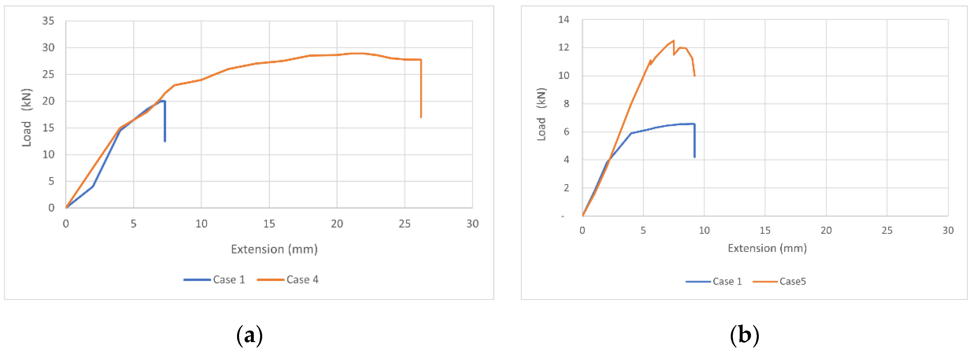
Figure 8 clearly portrays a significant increase in the load-bearing capacities of the carbon fiber-reinforced composites compared to the benchmark cases. Moreover, in Figure 8a, it is seen that the extension of the 40 × 80 beam was highly improved after reinforcement, indicating pseudo-ductility. The more the 40 × 80 beams were reinforced, the more they leaned on the ductile side of the curve. However, on the contrary, Figure 8b shows that there was little to no change in the extension value of the 40 × 40 beams, which shows that the more the 40 × 40 beams were reinforced, the more they diverted back to the brittle side of the curve.
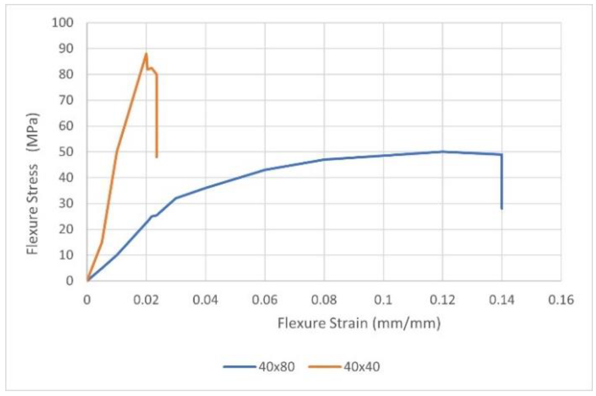
Pseudo-ductility can be further explained through the changes in E-modulus or modulus of elasticity (MOE) and time at break, as seen in Table 2. The MOE of the unreinforced cases in both sets of samples (Case 1) resembled the MOE of radiata pine species, which ranged between 2200–4700 MPa [22]. However, in the reinforced cases we saw changes in the MOE and time at break that differed with each set. For the set of 40 × 80 samples, the MOE decreased, which indicated the shift to ductility. This set’s time at break also drastically increased, implying a slower deformation. However, as the carbon ratio increased with the small cross-section (40 × 40), the MOE increased, hence shifting back to brittleness even slightly more than the benchmark case 1. The time at break for this set was almost similar to the benchmark case. Figure 9 compares the flexure stress and flexure strain graphs of the most promising cases of the 40 × 80 and 40 × 40 pieces, side by side, where the pseudo-ductility property is graphically observed.
With a higher modulus of toughness (usually calculated as the area under the curve in stress–strain graphs, see Figure 9), the 40 × 80 sample designs can also be used to make building structures and components that could be exposed to sudden impact loads such as earthquake loads.
To further increase the ductility of the reinforced section, it would be recommended that the wood pieces are free from any natural defects. Strain profile data revealed that the fiber reinforcement in the member’s tension zone maximized the effective material utilization in the member’s compression zone. The wood and the reinforcement material did not slide or creep at all.
3.2. Coefficient of Variation (CV)
Since three samples were tested for each reinforcement case, the coefficient of variation among the samples within each case was also calculated. The results demonstrated that the CV was as low as 1% for the most promising cases (Case 4 and Case 5) but as high as 13.2% for the unreinforced case (Case 1). Moreover, for the CV for the other cases (Cases 2, 3, and 4), the CV ranged between 1.9–17.1%. Considering that in each case one sample had natural defects (knots), the results from CV calculations portrayed that the carbon fiber reinforcement mechanisms also supplemented or offset the deficiencies caused by these natural defects.
3.3. GWP Comparison to Concrete of Similar Dimension
The GWP for each case was calculated and compared to the approximate GWP value of concrete of similar dimensions. For these calculations, concrete of grade C40 (40 MPa) was selected because it is the most common grade used for the construction of beam elements. The GWP of the case 4 composite was seen to be about 80% less than that of concrete, even with 24% more flexural strength (see Table 3).
4. Discussion
4.1. Opportunities
The overall insight here is that the larger the cross-sectional area, the easier the material can extend when the correct proportional number of carbon fibers is used for reinforcement. In the pseudo-ductile phase, the composite took time to break and the slow deformation was visible, acting as a warning when the beam was about to fail (See Figure 6). The 40 × 40 samples underwent a sudden and brittle failure despite the ability to withstand more extensive amounts of load even when the composite was out of the pseudo-ductile phase. For these samples (40 × 40), Case 5 was more effective by portraying up to an 80% increase in its bearing capacity compared to its unreinforced state.
Previous researchers noted concerns about the bonding quality and integrity of glulam and cross-laminated timber, the most frequently used MET so far [4]. On the contrary, the reinforcement mechanisms employed in this research showed promising performance in terms of delamination and creep prevention, a problem that was also observed in other reinforcement mechanisms in past experiments, especially those using fiber sheets on only the bottom of the beam [3,7,8,9,12,23]. These reinforcement mechanisms, especially case 5, were also proven to be effective in crack propagation prevention, similar to the study by Corradi et al. where carbon fiber patches were used instead [24].
4.2. Sample Application on a Slightly Larger Scale
Carbon fiber-reinforced timber beams have advantages, since they lend themselves to applications that are simple to construct and extremely versatile, both for recovering existing structures and designing new structures.
Timber has become a serious and attractive alternative in construction and has been used as a supplement to concrete structures in composite and hybrid concrete–timber construction systems. If such proper reinforcement mechanisms are used to strengthen the timber elements, beams can become more effective and further supplement concrete structures, hence creating a more sustainable construction process.
This mechanism could be applied to enhance the mechanical properties of various timber structures, from beams and columns in buildings to small interior and exterior designs, such as benches and pergolas, by strategically reinforcing them with carbon fibers using the designed mechanisms and patterns. Due to the combined advantages that the new reinforced composite possesses, topology optimization can also be performed to reduce the amount of material used in a structure without compromising the structural integrity of frames. The results from this experiment portrayed promising results of load-bearing capacities and pseudo-ductility, which inspired an application of the reinforcement mechanism on a slightly larger-scale bench.
The case study of this bench (3000 × 600 × 100 mm3) involved the application of strategically placed fiber reinforcement: longitudinal fibers for structural support and lateral fibers for holding the planks together (see Figure 10). Even though the bench had a distinctly curvilinear geometry to provide good ergonomics for different sitting and leaning positions, it resembled a simple, supported beam on two ends. It represents an investigation into the implications and limitations of a large-scale application as a full-size building component would. The bench was computer numerical control (CNC) milled with a robotic arm, carving the shape into a block of glued and reclaimed wood planks from a commercial building in Singapore. Grooves were carved into the shape during the machining process and accommodated the application of 12 K carbon fiber tows. The fibers bonded well with the timber block through the filling of the grooves with resin, sanding, and a final layer of matte coating. The bench has been outdoors and in use since December 2018 and shows wear and tear only on the finishing, but not from a structural perspective. One current limitation is the easy yet entirely manual fiber laying; a specific machine process could be developed with fiber laying robotic arms, as previous research has demonstrated [25], particularly on less complex geometries such as simple beams.
4.3. Challenges
The challenge of using this method includes the potential difficulty in obtaining precision for mass production of such elements without the wearing of the carbon fibers in the process. Another challenge is the end-of-life emissions involved in the recycling of such composites. It is questionable if it is feasible to effectively separate the carbon fiber from the timber during recycling or upcycling [16,26].
Due to testing the machine constraints and the ease to create grooves for the fibers in the small-scaled beams, the slenderness ratio selected did not meet the minimum ratio required by ISO standards. Further research is therefore needed to investigate how these mechanisms would perform in the correct slenderness of the beams.
5. Conclusions
Timber has become a serious and attractive alternative in construction and has been used to supplement or even replace concrete structures in composite and hybrid concrete–timber construction systems. This research has proven that if reinforcement mechanisms with synthetic fibers are used to strengthen New Zealand pine (radiata pine) wood elements, beams can become more effective structurally and further supplement concrete structures, creating a more sustainable construction process. Carbon fiber-reinforced timber beams are easy to construct and adaptable enough to be utilized for both repairing existing structures and building new ones. Aside from their exceptional mechanical characteristics, carbon fibers offer a high stress-tolerance capacity and a low thermal-expansion coefficient. Some of the results showed that, even though some of the designs underwent a massive failure, they were still capable of bearing large load capacities, and for a long time, before their failure.
Case number 4 and Case number 5 were proven to be the most promising cases due to their coverage and targeted reinforcement for prevention of crack propagation, respectively. However, with respect to pseudo-ductility, the carbon ratio of the 40 × 80 pieces was shown to be the most optimal in obtaining the maximum ductility with an optimum load-bearing capacity. Using the variations of these designs and their outcomes from the experiments, guidelines are being created to be adapted and implemented by other researchers with varying scales and cross-sectional areas to obtain the optimum mechanical properties’ enhancement without jeopardizing the GWP of the composite created. This research contributes a way to reinforce timber beams to enhance load-bearing capacities and pseudo-ductility without creep or delamination. Timber beams could now withstand larger amounts and varying types of loads for much smaller amount of timber used, hence significantly reducing the amount of GHG emissions contributed by construction processes.
Author Contributions
Conceptualization, D.S.M. and M.B.; methodology, D.S.M.; validation, D.S.M. and M.B.; formal analysis, D.S.M.; investigation, D.S.M.; resources, D.S.M.; data curation, D.S.M.; writing—original draft preparation, D.S.M.; writing—review and editing, D.S.M. and M.B.; visualization, D.S.M.; supervision, D.S.M. and M.B.; project administration, D.S.M. and M.B. All authors have read and agreed to the published version of the manuscript.
Funding
This research received no external funding.
Data Availability Statement
Not applicable.
Acknowledgments
Although this research received no external funding, we acknowledge the use of resources such as machinery, simulation software, labs, and storage facilities at the Singapore University of Technology and Design (SUTD). The bench design that illustrates a potential large-scale application was designed in collaboration with Kenneth Tracy (Dynamic Assembly Lab at SUTD) and supported by students in an undergraduate research opportunity (UROP) project at SUTD. The bench was generously funded by Mapletree Investment Pte Ltd. and supported with reclaimed wood planks from Vivocity.
Conflicts of Interest
The authors declare no conflict of interest on any of the data or results obtained from this experiment/research. Although an example given at the end of this manuscript (the bench) was funded by a third party, we declare that this third party did not partake in any activity regarding the research, or the experiments’ analyses written herein. The funders had no role in the design of the study; in the collection, analyses, or interpretation of data; in the writing of the manuscript; or in the decision to publish the results.
References
- Jacquier, N. Development and Evaluation of Mechanical Joints for Composite Floor Elements with Cross Laminated Timber. Ph.D. Thesis, Luleå Tekniska Universitet, Luleå, Sweden, 2015. [Google Scholar]
- Jeska, S.; Pascha, K.S. Emergent Timber Technologies: Materials, Structures, Engineering, Projects; Birkhäuser: Basel, Switzerland, 2014; p. 176. [Google Scholar] [CrossRef]
- Borri, A.; Corradi, M.; Speranzini, E. Reinforcement of wood with natural fibers. Compos. Part B Eng. 2013, 53, 1–8. [Google Scholar] [CrossRef]
- Knorz, M.; Torno, S.; van de Kuilen, J.W. Bonding quality of industrially produced cross-laminated timber (CLT) as determined in delamination tests. Constr. Build. Mater. 2017, 133, 219–225. [Google Scholar] [CrossRef]
- Okuda, S.; Corpataux, L.; Muthukrishnan, S.; Wei, K.H. Cross-Laminated Timber with Renewable and Fast Growing Tropical Species in South East Asia. In Proceedings of the WCTE 2018—World Conference on Timber Engineering, Seoul, Korea, 20–23 August 2018. [Google Scholar]
- O’Ceallaigh, C.; Sikora, K.; Harte, A.M. The influence of panel lay-up on the characteristic bending and rolling shear strength of CLT. Buildings 2018, 8, 114. [Google Scholar] [CrossRef]
- Globa, A.; Subhani, M.; Moloney, J.; Al-Ameri, R. Carbon fiber and structural timber composites for engineering and construction. J. Archit. Eng. 2018, 24, 04018018. [Google Scholar] [CrossRef]
- Rescalvo, F.J.; Valverde-Palacios, I.; Suarez, E.; Gallego, A. Experimental comparison of different carbon fiber composites in reinforcement layouts for wooden beams of historical buildings. Materials 2017, 10, 1113. [Google Scholar] [CrossRef] [PubMed]
- Bhat, J.A. Effect of CFRP-Reinforcement variation on the strength parameters of different timber beams. Mater. Today Proc. 2021, 44, 2785–2791. [Google Scholar] [CrossRef]
- Khelifa, M.; Lahouar, M.A.; Celzard, A. Flexural strengthening of finger-jointed Spruce timber beams with CFRP. J. Adhes. Sci. Technol. 2015, 29, 2104–2116. [Google Scholar] [CrossRef]
- Blaß, H.J.; Romani, M. Reinforcement of Glulam Beams with FRP Reinforcement; Karlsruhe Institute of Technology Library: Karlsruhe, Germany, 1998; pp. 1–7. Available online: https://holz.vaka.kit.edu/public/23.pdf (accessed on 21 June 2022).
- Neubauerová, P. Timber beams strengthened by carbon—Fiber reinforced lamellas. Procedia Eng. 2012, 40, 292–297. [Google Scholar] [CrossRef]
- Gómez, E.; González, M.; Hosokawa, K.; Cobo, A. Experimental study of the flexural behavior of timber beams reinforced with different kinds of FRP and metallic fibers. Compos. Struct. 2019, 213, 208–316. [Google Scholar] [CrossRef]
- Gustavsson, L.; Pingoud, K.; Sathre, R. Carbon dioxide balance of wood substitution: Comparing concrete- and wood-framed buildings. Mitig. Adapt. Strateg. Glob. Change 2006, 11, 667–691. [Google Scholar] [CrossRef]
- Sev, A. How can the construction industry contribute to sustainable development? A conceptual framework. Sustain. Dev. 2009, 17, 161–173. [Google Scholar] [CrossRef]
- Meng, F.; Olivetti, E.A.; Zhao, Y.; Chang, J.C.; Pickering, S.J.; McKechnie, J. Comparing life cycle energy and global warming potential of carbon fiber composite recycling technologies and waste management options. ACS Sustain. Chem. Eng. 2018, 6, 9854–9865. [Google Scholar] [CrossRef]
- Robertson, A.B.; Lam, F.C.F.; Cole, R.J. A comparative cradle-to-gate life cycle assessment of mid-rise office building construction alternatives: Laminated timber or reinforced concrete. Buildings 2012, 2, 245–270. [Google Scholar] [CrossRef]
- Chand, S. Review carbon fibers for composites. J. Mater. Sci. 2000, 35, 1303–1313. [Google Scholar] [CrossRef]
- Harte, A.M.; Dietsch, P. Reinforcement of Timber Structures: A State-of-the-Art Report; Shaker: Düren, Germany, 2015. [Google Scholar]
- García, P.D.; Escamilla, A.C.; García, M.N.G. Bending reinforcement of timber beams with composite carbon fiber and basalt fiber materials. Compos. Part B Eng. 2013, 55, 528–536. [Google Scholar] [CrossRef]
- Raftery, G.M.; Harte, A.M. Low-grade glued laminated timber reinforced with FRP plate. Compos. Part B Eng. 2011, 42, 724–735. [Google Scholar] [CrossRef]
- Lindström, H.; Harris, P.; Sorensson, C.; Evans, R. Stiffness and wood variation of 3-year old Pinus radiata clones. Wood Sci. Technol. 2004, 38, 579–597. [Google Scholar] [CrossRef]
- Micelli, F.; Scialpi, V.; la Tegola, A. Flexural reinforcement of glulam timber beams and joints with carbon fiber-reinforced polymer rods. J. Compos. Constr. 2005, 9, 337–347. [Google Scholar] [CrossRef]
- Corradi, M.; Vemury, C.M.; Edmondson, V.; Poologanathan, K.; Nagaratnam, B. Local FRP reinforcement of existing timber beams. Compos. Struct. 2021, 258, 113363. [Google Scholar] [CrossRef]
- Venkatesan, C.; Velu, R.; Vaheed, N.; Raspall, F.; Tay, T.-E.; Silva, A. Effect of process parameters on polyamide-6 carbon fibre prepreg laminated by IR-assisted automated fibre placement. Int. J. Adv. Manuf. Technol. 2020, 108, 1275–1284. [Google Scholar] [CrossRef]
- Xu, Y.; Liu, Y.; Chen, S.; Ni, Y. Current overview of carbon fiber: Toward green sustainable raw materials. BioResources 2020, 15, 7234–7259. [Google Scholar] [CrossRef]
Figure 1.
Different reinforcement mechanisms (Cases 2, 3, 4, 5, 6) compared to the benchmark/unreinforced case (Case 1).
Figure 1.
Different reinforcement mechanisms (Cases 2, 3, 4, 5, 6) compared to the benchmark/unreinforced case (Case 1).

Figure 2.
(a) A milling machine grooving design patterns for fibers’ lamination; (b) Case 2 and Case 3 samples (bottom side up) after grooving, next to benchmark case 1.
Figure 2.
(a) A milling machine grooving design patterns for fibers’ lamination; (b) Case 2 and Case 3 samples (bottom side up) after grooving, next to benchmark case 1.

Figure 3.
(a) Some of the radiata pine sample pieces ready for testing. (b) Experiment setup showing reaction-bearing plates used at supports and between the loading anvil and the sample.
Figure 3.
(a) Some of the radiata pine sample pieces ready for testing. (b) Experiment setup showing reaction-bearing plates used at supports and between the loading anvil and the sample.

Figure 4.
A slow deformation is seen at the compression (top) zone of the 40 × 80 beam sample.

Figure 5.
A 40 × 80 sample piece from benchmark case 1 (left) compared to the most promising reinforced 40 × 80 sample Case 4 (right) after loading.
Figure 5.
A 40 × 80 sample piece from benchmark case 1 (left) compared to the most promising reinforced 40 × 80 sample Case 4 (right) after loading.

Figure 6.
A 40 × 40 sample piece from benchmark case 1 (left) compared to the most promising reinforced 40 × 40 sample Case 5 (right) after loading.
Figure 6.
A 40 × 40 sample piece from benchmark case 1 (left) compared to the most promising reinforced 40 × 40 sample Case 5 (right) after loading.
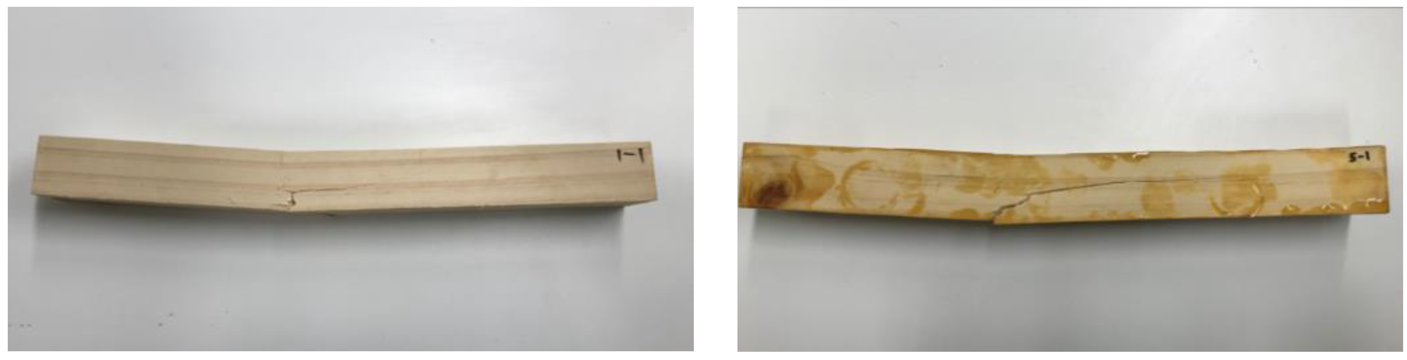
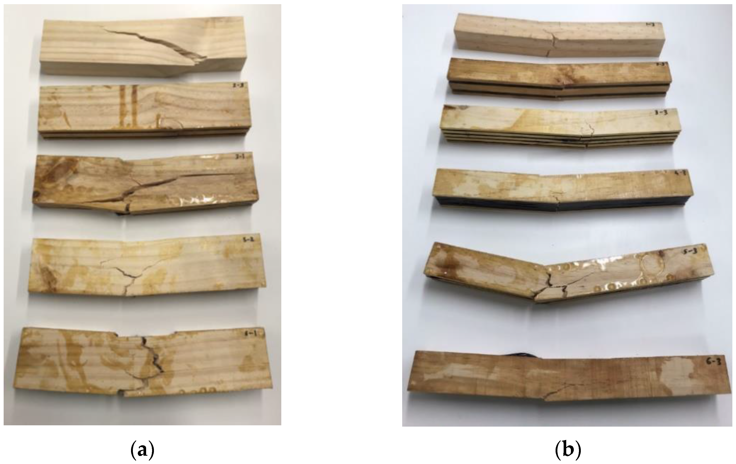
Figure 7.
Some pieces from each design case after testing: (a) 40 × 80 mm cross-sectional samples, (b) 40 × 40 mm cross-sectional samples.
Figure 7.
Some pieces from each design case after testing: (a) 40 × 80 mm cross-sectional samples, (b) 40 × 40 mm cross-sectional samples.

Figure 8.
Load vs. extension graph of (a) Case 1, 40 × 80 sample pieces, vs. Case 4, 40 × 80 sample pieces; and (b) Case 1, 40 × 40 sample pieces, vs. Case 5, 40 × 40 sample pieces.
Figure 8.
Load vs. extension graph of (a) Case 1, 40 × 80 sample pieces, vs. Case 4, 40 × 80 sample pieces; and (b) Case 1, 40 × 40 sample pieces, vs. Case 5, 40 × 40 sample pieces.

Figure 9.
Flexure stress vs. flexure strain graph of case 4, 40 × 80 sample pieces, compared to case 5, 40 × 40 sample pieces.
Figure 9.
Flexure stress vs. flexure strain graph of case 4, 40 × 80 sample pieces, compared to case 5, 40 × 40 sample pieces.

Figure 10.
Application of the reinforcement mechanism onto a carbon fiber-reinforced timber bench.


Table 1.
Summary of the number of carbon fibers used to reinforce each case.
| Case No. | Total Number of Rounds at the Top * | Total Number of Rounds at the Bottom * | Total Fiber Length Used per 40 × 80 Piece (m) * | Total Fiber Length Used per 40 × 40 Piece (m) * | Carbon Fiber Grams Used per 40 × 80 Piece (g) | Carbon Fiber Grams Used per 40 × 40 Piece (g) |
|---|---|---|---|---|---|---|
| 1 | 0 | 0 | 0 | 0 | 0 | 0 |
| 2 | 7 | 6 | 4.87 | 4.71 | 3.70 | 3.58 |
| 3 | 5 | 4 | 3.47 | 3.31 | 2.64 | 2.52 |
| 4 | 7 | 7 | 5.22 | 5.06 | 3.97 | 3.85 |
| 5 | 6 | 6 | 4.52 | 4.36 | 3.44 | 3.31 |
| 6 | 8 | 8 | 5.92 | 5.76 | 4.50 | 4.38 |
* Each indicating a 12 K carbon fiber tow (each tow contains 12,000 strands of fibers).
Table 2.
Summary of results from the experiments.
| Maximum Load [N] | Flexure Stress at Maximum Load [MPa] | Energy at Maximum Load [J] | Flexure Extension at Maximum Load [mm] | Modulus (E-Modulus) [MPa] | Time at Break [s] | ||
|---|---|---|---|---|---|---|---|
| 40 × 80 Pine samples | Case 1 | 18,948 | 33.31 | 45.70 | 4.16 | 2362 | 52 |
| Case 2 | 25,945 | 45.61 | 196.99 | 12.20 | 1998 | 152 | |
| Case 3 | 26,295 | 46.22 | 347.67 | 18.34 | 1567 | 229 | |
| Case 4 1 | 28,295 | 49.74 | 488.21 | 22.82 | 1199 | 325 | |
| Case 5 | 26,706 | 46.94 | 317.39 | 17.03 | 1685 | 234 | |
| Case 6 | 26,427 | 46.46 | 410.84 | 21.64 | 1327 | 270 | |
| 40 × 40 Pine samples | Case 1 | 7020 | 49.36 | 45.36 | 8.89 | 4468 | 113 |
| Case 2 | 9407 | 66.15 | 43.92 | 8.14 | 4715 | 101 | |
| Case 3 | 9962 | 70.05 | 53.12 | 8.53 | 5900 | 106 | |
| Case 4 | 10,743 | 75.54 | 106.38 | 13.76 | 5264 | 172 | |
| Case 5 2 | 12,654 | 88.98 | 50.63 | 7.49 | 6213 | 112 | |
| Case 6 | 10,449 | 73.47 | 93.41 | 12.74 | 4604 | 159 | |
1 Most promising case for the 40 × 80 samples. 2 Most promising case for the 40 × 40 samples.
Table 3.
GWP of case number 4 compared to concrete of similar dimensions.
| Case #4 | Cross Section | Volume (m3) | GWP (kg CO2 -e) | Flexural Strength (MPa) |
|---|---|---|---|---|
| Timber | 40 × 80 | 0.00056 | 0.1191 (−80%) | 49.74 (+24%) |
| Concrete | 40 × 80 | 0.00112 | 0.55664 | 40 |
Publisher’s Note: MDPI stays neutral with regard to jurisdictional claims in published maps and institutional affiliations. |
© 2022 by the authors. Licensee MDPI, Basel, Switzerland. This article is an open access article distributed under the terms and conditions of the Creative Commons Attribution (CC BY) license (https://creativecommons.org/licenses/by/4.0/).
Share and Cite
MDPI and ACS Style
Mlote, D.S.; Budig, M. Load-Bearing Capacities and Pseudo-Ductility of Carbon Fiber-Reinforced New Zealand Pine Timber Beams. J. Compos. Sci. 2022, 6, 239. https://doi.org/10.3390/jcs6080239
AMA Style
Mlote DS, Budig M. Load-Bearing Capacities and Pseudo-Ductility of Carbon Fiber-Reinforced New Zealand Pine Timber Beams. Journal of Composites Science. 2022; 6(8):239. https://doi.org/10.3390/jcs6080239
Chicago/Turabian StyleMlote, Doreen Steven, and Michael Budig. 2022. "Load-Bearing Capacities and Pseudo-Ductility of Carbon Fiber-Reinforced New Zealand Pine Timber Beams" Journal of Composites Science 6, no. 8: 239. https://doi.org/10.3390/jcs6080239