Article

The Effect of Pulse Current on Electrolytically Plating Nickel as a Catalyst for Grafting Carbon Nanotubes onto Carbon Fibers via the Chemical Vapor Deposition Method

Department of Biomedical Engineering, Doshisha University, Kyotanabe 610-03948580, Japan
*
Author to whom correspondence should be addressed.
J. Compos. Sci. 2023, 7(2), 88; https://doi.org/10.3390/jcs7020088
Submission received: 9 December 2022 / Revised: 21 January 2023 / Accepted: 13 February 2023 / Published: 19 February 2023
(This article belongs to the Special Issue Carbon Fiber Composites, Volume II)

Abstract

:
Carbon nanotubes (CNTs) can be directly grafted onto the surface of carbon fibers using the chemical vapor deposition method, in which nanometer-order nickel (Ni) particles, serving as catalysts, are plated onto the surface of carbon fibers via electrolytic plating. In our previous studies, in which a direct current (DC) was used to electrolytically plate Ni onto carbon fibers as a catalyst, the site densities and diameters of Ni particles increased simultaneously with the plating time, making it difficult to independently control the site densities and diameters of the particles. On the other hand, pulse current (PC) plating is attracting attention as a plating technique that can control the deposition morphology of nuclei. In this study, we clarify the effect of the parameters of the PC on the particle number per unit area (site density) and the particle diameters of Ni particles plated onto the surface of carbon fibers, using the PC to electrolytically plate Ni. Electrolytically plating Ni onto carbon fibers (via PC) after the removal of the sizing agent enable Ni particles with sparser site densities and larger diameters to be plated than those plated via DC. Using Ni particles with sparse site densities, it is shown that CNTs with sparse site densities can be grafted.

1. Introduction

Carbon nanotubes (CNTs) are cylinders with diameters in the order of nanometers wound with graphene, which is a sheet-like structure consisting of single carbon atoms interconnected in a hexagonal lattice structure. CNTs can be generated via several methods, such as the arc discharge method, the laser ablation method and the chemical vapor deposition (CVD) method. The arc discharge method, in which carbon electrodes containing metal catalysts are evaporated by arc discharge, and the laser ablation method, in which graphite mixed with metal catalysts is evaporated by YAG laser irradiation, require temperatures above 1000 °C and produce only a few CNTs [1]. On the other hand, the CVD method, in which CNTs are generated on a metal catalyst by supplying gas containing carbon atoms in an inert atmosphere, can produce CNTs at relatively low temperatures and in large amounts [1]. CNTs have attracted attention as additives for fiber-reinforced plastics (FRPs) because of their advantages derived from graphene, such as nanoscale, high strength, high stiffness, and excellent electrical conductivity. Recently, one method of adding CNTs to carbon-fiber-reinforced plastics (CFRPs), a technique of grafting CNTs onto the surface of carbon fibers, has been developed to improve various properties of CFRPs [2,3,4,5,6,7,8]. This method has the advantage that agglomeration of CNTs is less likely to occur compared to the method in which CNTs are dispersed in the matrix. There are various metal catalysts that can be used in CNT grafting via the CVD method. Particularly, nickel (Ni) can be attached to the surface of carbon fibers more easily than iron (Fe) and cobalt (Co) via electrolytic plating; thus, CNTs can be selectively grafted onto the surface of carbon fibers in the CVD method. Sputtering is sometimes used to attach metal catalysts on substrates, but its drawbacks include the difficulty of attaching the catalyst on the inner surface of the carbon fibers in the fiber bundle and the high cost of the equipment. The disadvantage of Fe plating and Co plating is that the plating bath is easily oxidized and unstable. For the CVD method using ferrocene (Fe(C5H5)2), which contains Fe as a metal catalyst element, it is difficult to control the location of CNT grafting, and this method requires a relatively high temperature of 750–1000 °C [9,10]. Ethanol is a carbon source used in CNT grafting via the CVD method because it is easier to handle than using methane and acetylene, and the grafting temperature can be lowered. Due to the lower processing temperature when using ethanol as a carbon source, the thermal degradation of carbon fibers can be reduced. In previous studies, CNTs were grafted onto carbon fibers at over 700 °C and the tensile strength of CNT-grafted carbon fibers was decreased due to degradation by oxidation [11,12]. We have developed a method to directly graft CNTs onto the surface of carbon fibers at a relatively lower temperature of 600 °C via the CVD method using ethanol (C2H5OH) as a carbon source, in which Ni particles from a nanometer order to a sub-micrometer order, serving as catalysts, are plated onto the surface of carbon fibers via electrolytic plating [13,14,15]. In studies regarding the grafting of CNTs onto carbon fibers via the CVD method using various catalysts, not only Ni, it has been reported that grafting CNTs onto the surface of carbon fibers can provide not only high fiber/matrix interfacial shear strength (IFSS) [16,17,18,19,20] due to the anchoring effect, but also a high level of resin impregnation into the fiber bundle [21,22] due to the capillary force of CNTs. In other words, it is expected that carbon-fiber-reinforced thermoplastics (CFRTPs) with superior mechanical properties can be obtained using CNT-grafted carbon fibers as they can improve both the fiber/resin IFSS and resin impregnation properties. On the other hand, excessive grafting of CNTs may cause agglomerated CNTs to be the crack initiation of a fracture [23] and inhibit resin impregnation into the fiber bundle [22], meaning the CNT grafting conditions need to be optimized.
Zhang et al. proposed two conditions regarding CNT grafting to provide CFRPs with superior mechanical properties with CNT-grafted carbon fibers as follows: a sparser site density of CNTs to reduce the number of stress concentrations at the ends of CNTs; and a longer length of CNTs to strengthen the resin layer [24]. However, a method to reduce the site density of CNTs on carbon fibers has not been yet developed. Using finite element analyses, Jia et al. suggested that there is a correlation between the diameter of CNTs grafted onto carbon fibers and interfacial shear strength [25]. This showed that it is necessary to develop a method to graft CNTs with a sparse site density and a large diameter onto carbon fibers. Meanwhile, past studies, in which silicon was used as a substrate, have shown that CNTs were grafted using catalyst particles with controlled numbers and diameters. It has been reported that the site densities and diameters of catalyst particles and the site densities and diameters of CNTs have correlations [26,27,28,29].
In our previous studies, in which a direct current (DC) was used for to electrolytically plate Ni onto carbon fibers as a catalyst, the site densities and diameters of Ni particles increased simultaneously with the plating time [30], making it difficult to independently control the site densities and diameters of these particles, i.e., the site densities and diameters of CNTs. In other words, if the plating time is shortened in order to reduce the site densities of particles to graft CNTs at a sparse site density, the particles’ diameters also decrease. On the other hand, pulse current (PC) plating is attracting attention as a plating technique that can control the deposition morphology of nuclei. PC plating is generally used to obtain a plating film with a higher site density and a smaller diameter of nuclei by applying a larger current compared to DC plating [31,32]. Conversely, PC plating with a smaller current can promote nuclei growth while suppressing nucleation [33]. This can be applied to control the site density and diameter of Ni particles on carbon fibers. Pulse plating includes parameters such as current value (current, I), current density (J), plating time per pulse cycle (ON-time, tON), off time per pulse cycle (OFF-time, tOFF) and the sum of the ON-time (actual total plating time, t), and it is necessary to clarify the effect of each of these parameters on the deposition morphology of Ni particles.
In this study, we clarify the effects of the parameters of the PC on the particle number per unit area (site density) and the particle diameter of Ni particles plated onto the surface of carbon fibers, using the PC to electrolytically plate Ni. Moreover, CNTs grafted onto carbon fibers via Ni particles with sparse site densities were observed using FE-SEM.

2. Materials and Methods

2.1. Materials and Sizing Agent Removal Method

Spread PAN-based carbon fibers (24 K, 23 mm width, 100 mm length, Nippon Tokushu Fabric, Japan) were used in this study. Generally, the sizing agent applied to the surface of carbon fibers serves as an insulating material for electrolytic plating. In our previous study, we reported that for carbon fibers with a sizing agent, Ni particles were less likely to be plated in areas where the sizing agent adhered, and Ni particles were concentrated in areas where the sizing agent did not adhere, resulting in an uneven distribution of Ni particles. Meanwhile, for unsized carbon fiber, Ni particles were plated evenly in all areas [16]. In this study, in order to reduce the effect of the sizing agent on Ni deposition, the sizing agent was removed. The sizing agent on the surface of the carbon fiber was removed via heat treatment at a temperature of 350 °C and at a holding time of 20 min in an argon (Ar) atmosphere using a chemical vapor deposition system (CVD system, MPCVD-70, Microphase, Japan). When removing sizing agents by heat treatment, it is important to not cause unnecessary chemical reactions. In a conventional oven, air oxidation of the fiber surface and sizing agent is a concern during heating. Therefore, heat treatment was performed in a CVD system in which the atmosphere can be replaced by Ar. In our previous study, the sizing agent on the surface of the carbon fiber was removed by the same methodology used in this study. We reported that the surface of the treated carbon fiber had stripe patterns, although the surface of the untreated carbon fiber had less stripes. The surface of the carbon fiber was also analyzed by an X-ray photoelectron spectrometer (ESCA, KRATOS ULTRA2, Shimadzu Corp. Japan). Graphite was not observed on the untreated carbon fibers, whereas it was detected in the treated carbon fibers [34]. The unsized carbon fibers are referred to as “Unsized CF”.

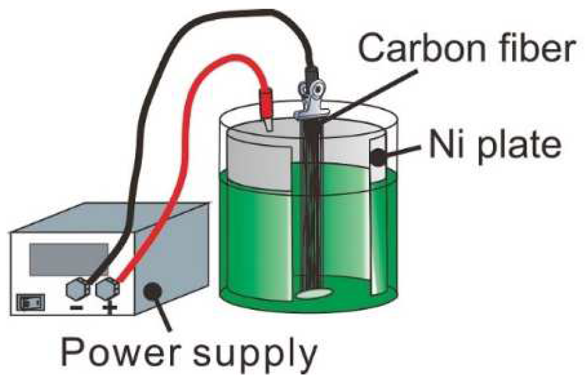
2.2. Electrolytic Ni Plating onto Carbon Fibers

Ni particles, as a catalyst for CNT grafting via the chemical vapor deposition (CVD) method, were plated onto the carbon fiber surface using an electrolytic Ni plating method. The components of the plating bath, namely a “Watts bath”, consisted of nickel sulfate hexahydrate (NiSO4·6H2O, 240 g/L), nickel chloride hexahydrate (NiCl2·6H2O, 45 g/L) and boric acid (H3BO3, 30 g/L). The temperature of the plating bath was 21 °C. The anode was connected to a Ni plate, and the cathode was connected to an Unsized CF, as shown in Figure 1. Two types of currents were used for electrolytic Ni plating, namely a direct current (DC) and a pulse current (PC). A schematic drawing of a PC wave is shown in Figure 2. For the DC, I = 200 Ma and t = 5 s were used as the standard conditions and for the PC, I = 200 Ma, tON = 10 ms, tOFF = 100 ms and t = 5 s were used as the standard conditions. Electrolytic Ni plating was performed under various conditions as shown in Table 1. When assigning one parameter to the various sets of numerical values, other parameters remained constant at the standard condition shown in bold in Table 1. Carbon fibers plated via DC are referred to as “D-Ni-CF”, and carbon fibers plated via the PC are referred to as “P-Ni-CF”. They are collectively referred to as “Ni-CF”. Ni particles on the surface of the carbon fiber were observed using a field-emission scanning electron microscope (FE-SEM, SU8020, Hitachi High-Technologies, Tokyo, Japan).

2.3. CNT Grafting onto Ni-CF via the CVD Method

CNTs were grafted onto the surface of Ni-CF via the CVD method using the CVD system, which is the same system used to remove the sizing agent. The grafting conditions of the CNTs were a grafting temperature of 600 °C, a grafting time of 10 min and 30 min, under a vacuum of −0.08 MPa and in an Ar atmosphere, and ethanol (C2H5OH) was supplied as a carbon source at 2 mL/min. CNT-grafted D-Ni-CF are referred to as “D-CNT10-CF” and “D-CNT30-CF”, and CNT-grafted P-Ni-CF are referred to as “P-CNT10-CF” and “P-CNT30-CF”. They are collectively referred to as “CNT-CF”. CNT-CFs were observed using FE-SEM. The outer diameters of CNT-CFs were measured via image-processing program ImageJ.

3. Results and Discussion

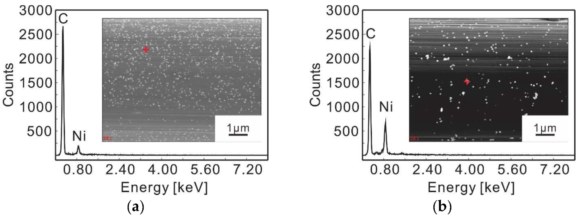
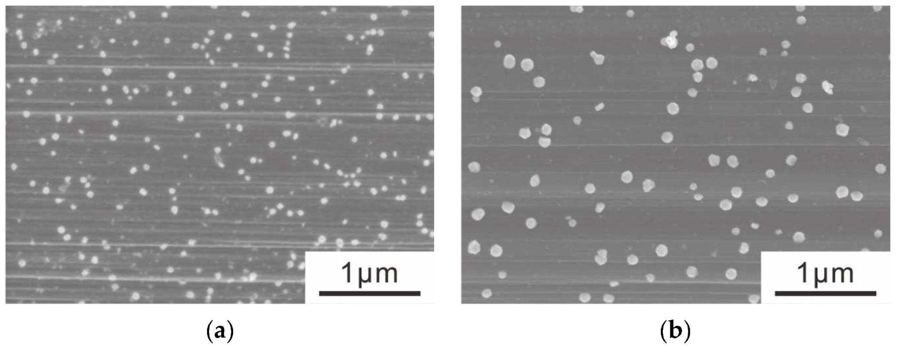
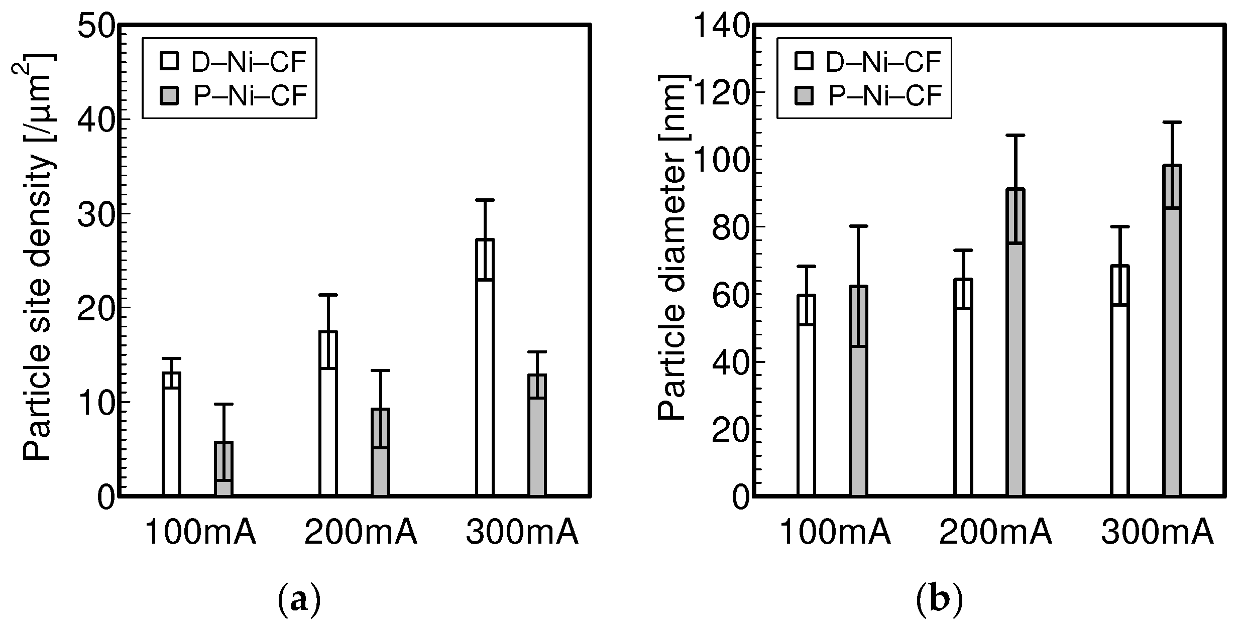
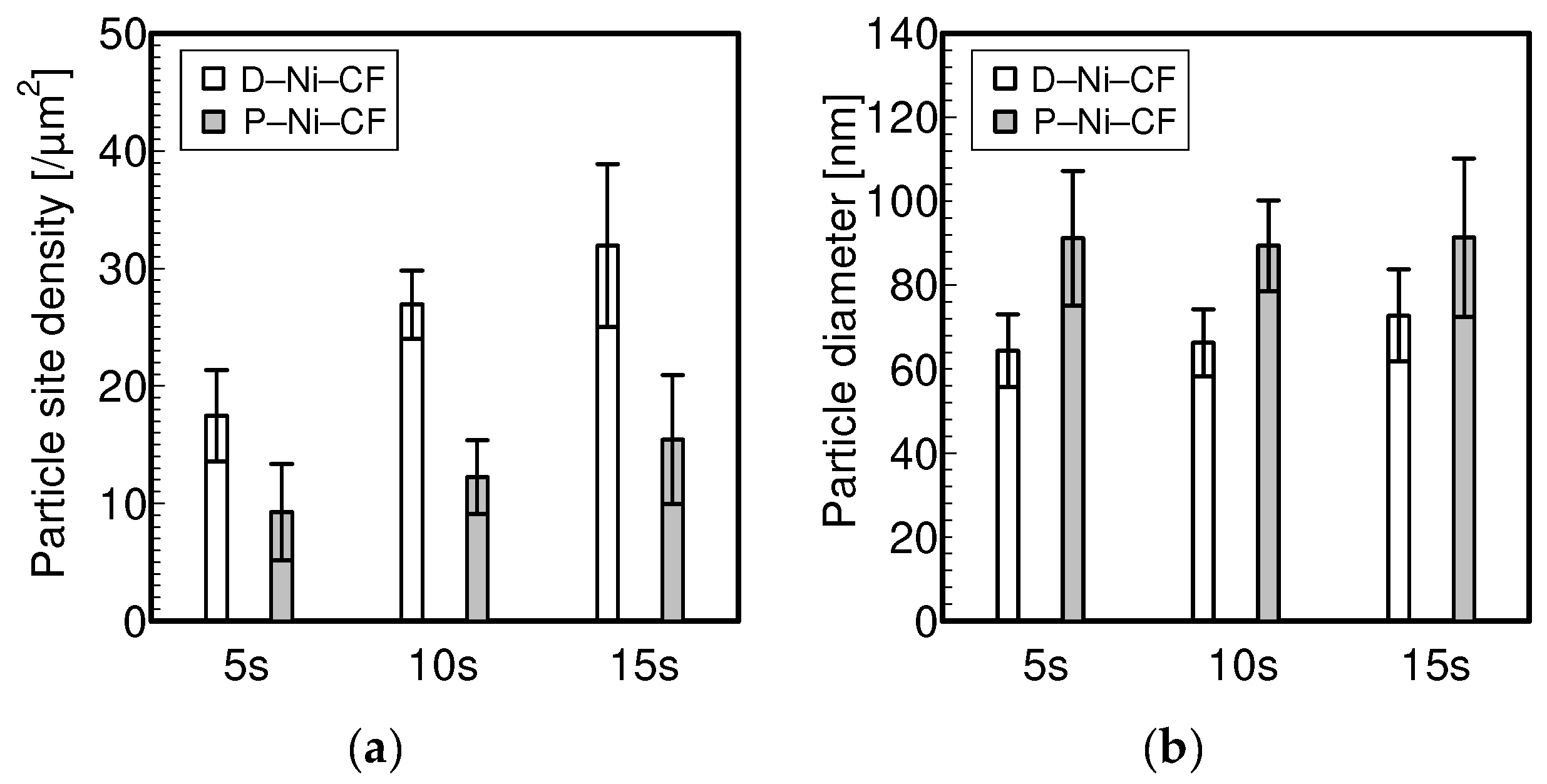
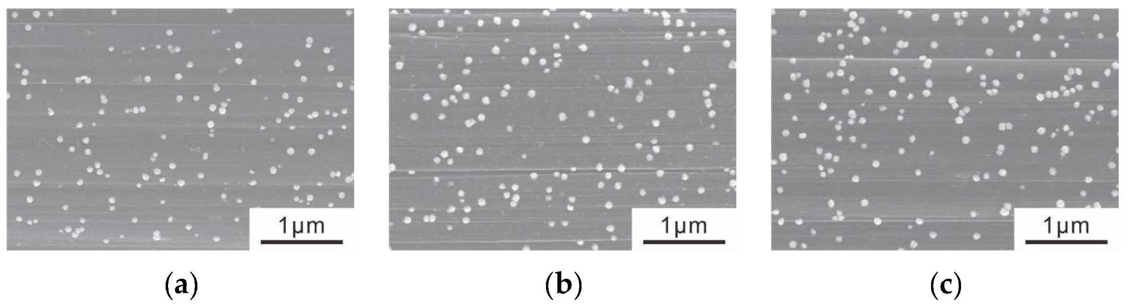
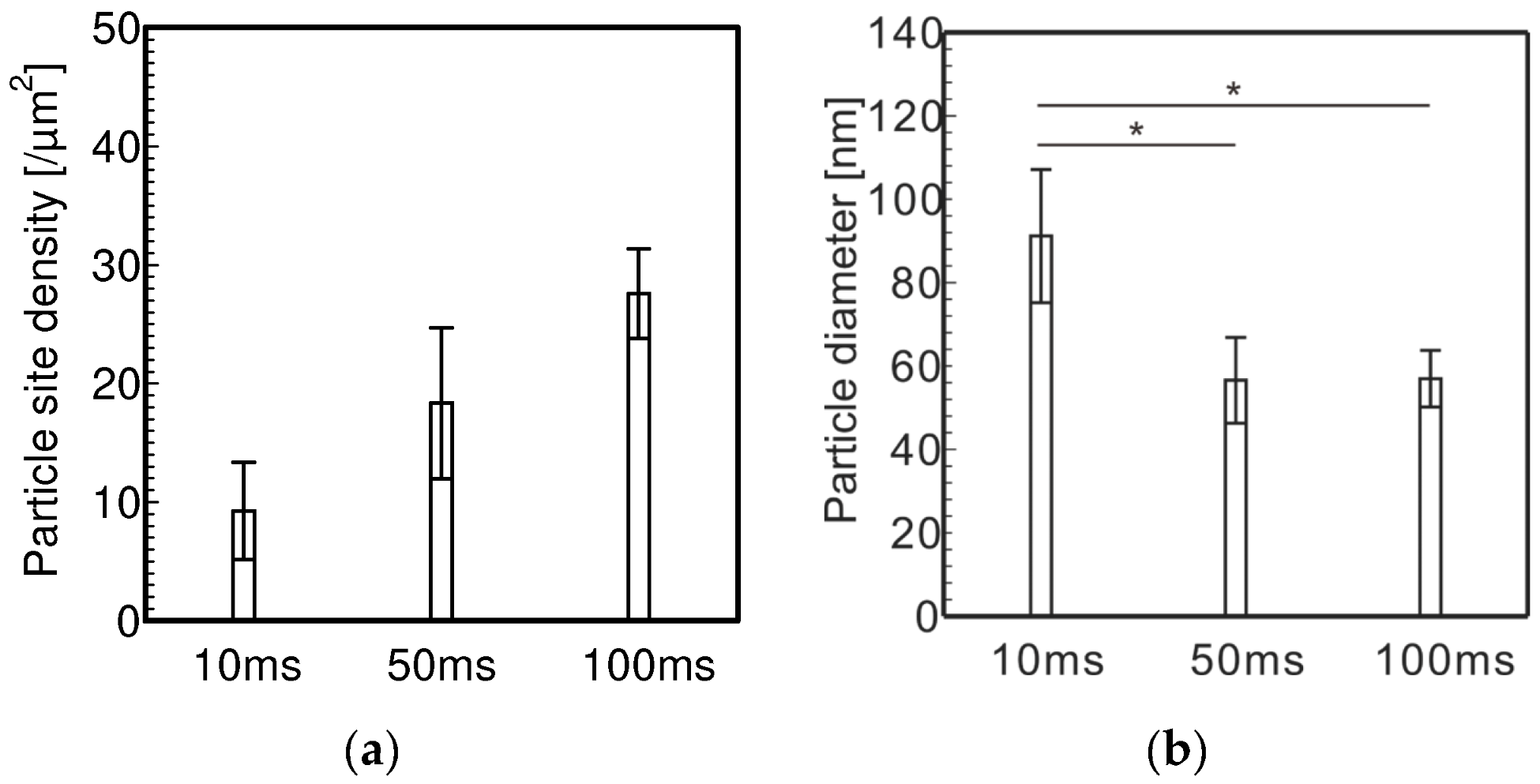
3.1. Electrolytic Ni Plating onto Carbon Fibers

Figure 3 shows the FE-SEM observations of the Ni-CF and the elemental analyses performed by the EDS of the FE-SEM. The results show that Ni particles were successfully plated onto the carbon fibers. The number of Ni particles on the center of a carbon fiber was counted in a 5 μm × 5 μm square of FE-SEM images (Figure 4) via image-processing program, ImageJ. The counted number was divided by 25 and converted to the particle number per 1 μm2 to obtain the site density. Figure 5 shows the enlarged FE-SEM images of Ni-CF. The diameters of the Ni particles were measured via ImageJ using these FE-SEM images. Figure 6 shows the particle site density and particle diameter of Ni-CF. It was found that P-Ni-CF had a sparser site density and a larger particle diameter than D-Ni-CF, although the same amounts of electrical current were supplied. It has been reported that when plating using pulse currents, most or part of the current is consumed to charge the electrical double-layer capacitance, resulting in less metal deposition [35]. However, in DC plating, the electrical double-layer capacitance is only charged once at the beginning of plating, while charging occurs during every pulse cycle in PC plating. In this study, the particle site density of Ni particles in P-Ni-CF is considered to be sparser than that in D-Ni-CF due to the same mechanism.
The equations of ionic reaction on the cathode side are shown in Equations (1) and (2).
Ni2+ + 2e = Ni
2H+ + 2e = H2
The cations involved in the reaction during plating are H+ and Ni2+. Figure 7 shows the possible mechanisms of (a) PC plating and (b) DC plating after the generation of Ni nuclei. The difference in hydrogen overvoltage [36] between nickel and carbon may have caused the following phenomena. Specifically, in the case of PC plating, when plating begins, H+, which has a higher mobility than metal ions [37], first attaches to the cathode surface (i); H+ on the surface of the Ni particle, which has a smaller hydrogen overvoltage than carbon, is hydrogenated (ii); and the hydrogen (H2) leaves the surface of the Ni particle (iii). Secondly, when Ni2+ fills the space vacated by the release of H2 (iv), Ni2+ is reduced and the diameter of the Ni particle increases (v), which is considered to be a cycle that results in the plating of Ni particles with a sparse particle site density and a large particle diameter. Meanwhile, in the case of DC plating, although H+ initially adheres to the cathode surface (i), it is considered that, due to the long plating time, all H+ on the cathode surface is hydrogenated regardless of the difference in hydrogen overvoltage (ii), and H2 leaves the surface of the cathode (iii). Next, Ni2+ is reduced on the cathode surface (iv, v), and then, not only do the nuclei grow, but also, new nuclei are generated. As a result, Ni particles with thick site densities and small diameters are considered to be plated.
Figure 8 shows the particle site density and the particle diameter of Ni-CF plated using different currents. The particle site densities and particle diameters of both D-Ni-CF and P-Ni-CF tend to increase with the current.
Figure 9 shows the particle site density and the particle diameter of Ni-CF plated using different actual total plating times. The particle site density increases with the actual total plating time in both D-Ni-CF and P-Ni-CF. The particle diameter is proportional to the increase in the actual total plating time for DC, while for PC, the particle size is independent of the actual total plating time within the range of 5 s to 15 s. This result is confirmed in the FE-SEM images shown in Figure 10.
Figure 11 shows the particle site density and the particle diameter of P-Ni-CF plated using different ON-times. The particle site density tends to increase with the ON-time. However, the particle diameter is large at 10 ms, but small at 50 ms and above. Particularly, in order to increase the particle diameter, the ON-time should be set to a value as small as 10 ms.
Figure 12 shows the particle site density and the particle diameter of the P-Ni-CF plate using different OFF-times. There is no difference in the particle site density and the particle diameter between OFF-times of 100 ms and 1000 ms. On the other hand, the particle site density is thicker and the particle diameters are smaller at an OFF-time of 10 ms. This behavior can be explained by the difference between the charging and discharging of the electrical double layer as shown in Figure 13. When the OFF-time of the PC is sufficiently longer, the charged electrical double layer is completely discharged and returns to its original uncharged state. Additionally, more current is consumed to charge the electrical double layer from the original uncharged state in the next ON-time. On the other hand, when the OFF-time is shorter, the next ON-time occurs before the electrical double layer is completely discharged and the electrical double layer is charged. In this case, the current consumed to charge the electrical double layer is considered to be smaller than the condition when the electrical double layer is charged from the original uncharged state. As shown in Figure 14, when the current is cut off at the OFF-time, the cations attracted near the cathode during the ON-time diffuse, and if the OFF-time is shorter, the cation diffusion distance is shorter and Ni2+ remains near the cathode until the next ON-time. H+ diffuses faster than metal ions, and its direction is considered to be random, meaning the location of H+ adsorption is considered to change each time during each pulse cycle. Therefore, Ni2+ near the cathode is considered to be adsorbed and reduced on the surface of the carbon fibers where H+ is not adsorbed. As a result of this mechanism, when the OFF-time is relatively longer (above 100 ms), Ni particles with sparse site densities and large diameters are plated. In order to use PC to plate Ni particles with sparse site densities and large diameters, the OFF-time should be set to a value as large as 100 ms.

3.2. CNT Grafting onto Ni-CF via the CVD Method

Figure 15 and Figure 16 show the FE-SEM images of CNT-CF. They show that P-Ni-CF, which has a sparser site density of Ni particles, obtained CNTs at a sparser site density than D-Ni-CF. Figure 17 shows the magnified FE-SEM images of CNTs. The white particles are the Ni particles. Thick CNTs tend to be grafted from larger Ni particles. Figure 18 shows the outer diameter of the CNT-CF, indicating that the longer the CNT grafting time is, the larger the outer diameters of the CNTs that are grafted onto the carbon fibers. This result indicates that longer CNTs are grafted within longer grafting times.

4. Conclusions

In this study, we have clarified the effects of the parameters of the pulse current (PC), such as the current, plating time per pulse cycle, off time per pulse cycle and sum of the plating time per pulse cycle, on the particle number per unit area (site density) and the particle diameters of nickel (Ni) particles plated onto the surface of carbon fibers using the PC to electrolytically plate Ni. Moreover, CNTs grafted via the chemical vapor deposition method (CVD method) were observed using FE-SEM. The investigation yielded the following conclusions:
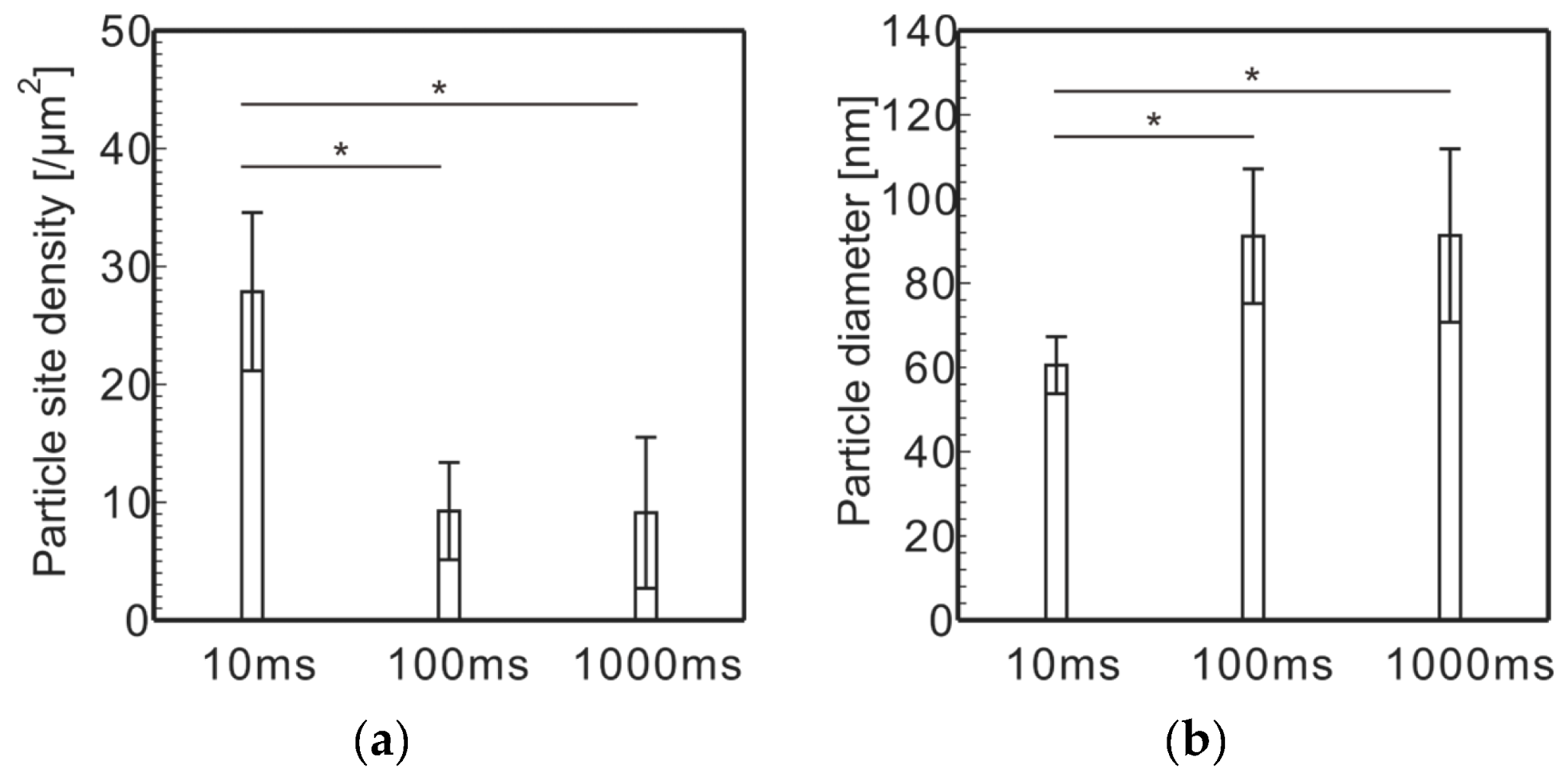
  • Electrolytically plating Ni onto carbon fibers via the PC after the removal of the sizing agent attached to the surface of carbon fiber enabled Ni particles with sparser site densities and larger diameters to be plated rather than those plated via a direct current.
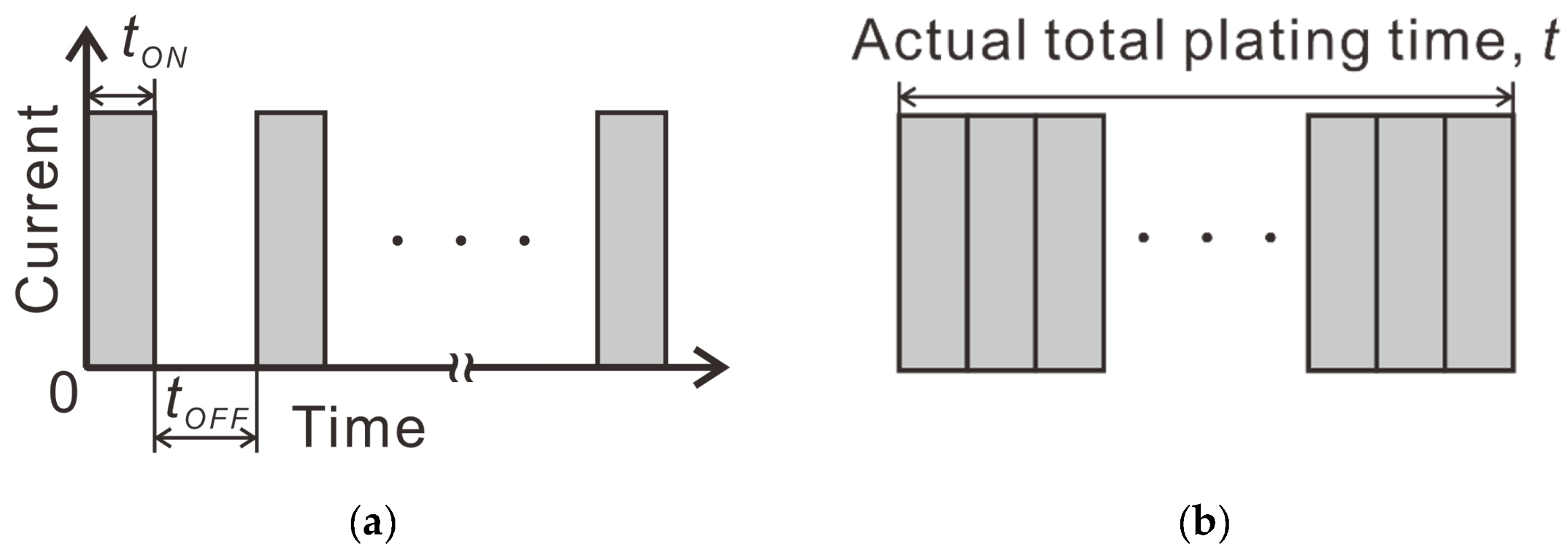
  • To electrolytically plate Ni with PC, it is necessary to shorten the plating time per pulse cycle to about 10 ms and lengthen the off time per pulse cycle to about 100 ms in order to plate Ni particles with sparse site densities and large diameters.
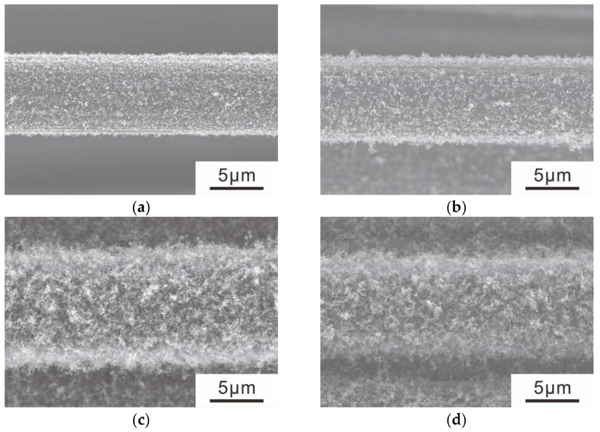
  • Using Ni particles with sparse site densities, CNTs with sparse site densities can be grafted.

Author Contributions

Conceptualization, K.T.; Data curation, S.K.; Funding acquisition, K.T.; Investigation, S.K.; Methodology, K.T.; Project administration, K.T.; Resources, K.T.; Supervision, K.T.; Validation, K.T. and S.K.; Visualization, S.K.; Writing—original draft, S.K.; Writing—review and editing, K.T. All authors have read and agreed to the published version of the manuscript.

Funding

This research was partially supported by JSPS KAKENHI (Japan Society for the Promotion of Science, Grant-in-Aid for Scientific Research (B), Grant Number JP19H02031).

Data Availability Statement

Not applicable.

Conflicts of Interest

The authors declare no conflict of interest.

References

  1. Das, R.; Shahnavaz, Z.; Ali, M.E.; Islam, M.M.; Abd Hamid, S.B. Can We Optimize Arc Discharge and Laser Ablation for Well-Controlled Carbon Nanotube Synthesis? Nanoscale Res. Lett. 2016, 11, 510. [Google Scholar] [CrossRef] [Green Version]
  2. Termine, S.; Trompeta, A.-F.A.; Dragatogiannis, D.A.; Charitidis, C.A. Novel CNTs grafting on carbon fibres through CVD: Investigation of epoxy matrix/fibre interface via nanoindentation. MATEC Web Conf. 2019, 304, 8. [Google Scholar] [CrossRef]
  3. Pozegic, T.R.; Jayawardena, K.D.G.I.; Chen, J.-S.; Anguita, J.V.; Ballocchi, P.; Stolojan, V.; Silva, S.R.P.; Hamerton, I. Development of sizing-free multi-functional carbon fiber nanocomposites. Compos. Part A Appl. Sci. Manuf. 2016, 90, 306–319. [Google Scholar] [CrossRef] [Green Version]
  4. Chen, J.; Xu, H.; Liu, C.; Mi, L.; Shen, C. The effect of double grafted interface layer on the properties of carbon fiber reinforced polyamide 66 composites. Compos. Sci. Technol. 2018, 168, 20–27. [Google Scholar] [CrossRef]
  5. Naito, K. Development of high-performance and multi-functional carbon fibers. JSPP 2012, 24, 127–134. [Google Scholar] [CrossRef]
  6. Wang, C.; Wang, Y.; Su, S. Optimization of Process Conditions for Continuous Growth of CNTs on the Surface of Carbon Fibers. J. Compos. Sci. 2021, 5, 111. [Google Scholar] [CrossRef]
  7. Badakhsh, A.; An, K.-H.; Kim, B.-J. Enhanced Surface Energetics of CNT-Grafted Carbon Fibers for Superior Electrical and Mechanical Properties in CFRPs. Polymers 2020, 12, 1432. [Google Scholar] [CrossRef]
  8. Lee, G.; Ko, K.D.; Yu, Y.C.; Lee, J.; Yu, W.-R.; Youk, J.H. A facile method for preparing CNT-grafted carbon fibers and improved tensile strength of their composites. Compos. Part A Appl. Sci. Manuf. 2015, 69, 132–1389. [Google Scholar] [CrossRef]
  9. Naito, K.; Nagai, C. Effect of carbon nanotube surface modification on tensile properties of carbon fiber epoxy impregnated bundle composites. Polym. Polym. Compos. 2022, 10, 1176–1179. [Google Scholar] [CrossRef]
  10. Komissarov, I.; Shaman, Y.; Fedotova, J.; Shulitski, B.; Zavadsky, S.; Kasiuk, J.; Karoza, A.; Pyatlitski, A.; Zhigulin, D.; Aleshkevych, P.; et al. Structural and magnetic investigation of single wall carbon nanotube films with iron based nanoparticles inclusions synthesized by CVD technique from ferrocene/ethanol solution. Phys. Status Solidi C 2013, 10, 1176–1179. [Google Scholar] [CrossRef]
  11. Li, W.Z.; Wang, D.Z.; Yang, S.X.; Wen, J.G.; Ren, Z.F. Controlled growth of carbon nanotubes on graphite foil by chemical vapor deposition. Chem. Phys. Lett. 2001, 335, 141–149. [Google Scholar] [CrossRef]
  12. Zhu, S.; Su, C.-H.; Lehoczky, S.L.; Muntele, I.; Ila, D. Carbon nanotube growth on carbon fibers. Diam. Relat. Mater. 2003, 12, 1825–1828. [Google Scholar] [CrossRef]
  13. Tanaka, K.; Okuda, S.; Hinoue, Y.; Katayama, T. Effects of Water Absorption on Fiber Matrix Interfacial Shear Strength of Carbon Nanotube Grafted Carbon Fiber Reinforced Polyamide Resin. J. Compos. Sci. 2019, 3, 4. [Google Scholar] [CrossRef] [Green Version]
  14. Tanaka, K.; Nishikawa, T.; Aoto, K.; Katayama, T. Effect of Carbon Nanotube Deposition Time to the Surface of Carbon Fibres on Flexural Strength of Resistance Welded Carbon Fibre Reinforced Thermoplastics Using Carbon Nanotube Grafted Carbon Fibre as Heating Element. J. Compos. Sci. 2019, 3, 9. [Google Scholar] [CrossRef] [Green Version]
  15. Tanaka, K.; Habe, R.; Tanaka, M.; Katayama, T. Carbon Fiber Reinforced Thermoplastics Molding by Using Direct Resistance Heating to Carbon Nanofilaments Grafted Carbon Fiber. J. Compos. Sci. 2019, 3, 14. [Google Scholar] [CrossRef] [Green Version]
  16. Tanaka, K.; Yamada, K.; Hinoue, Y.; Katayama, T. Influence of unsizing and carbon nanotube grafting of carbon fibre on fibre matrix interfacial shear strength of carbon fibre and polyamide 6. Key Eng. Mater. 2020, 827, 178–183. [Google Scholar] [CrossRef]
  17. Lee, G.; Sung, M.; Youk, J.H.; Lee, J.; Yu, W.R. Improved tensile strength of carbon nanotube-grafted carbon fiber reinforced composites. Compos. Struct. 2019, 220, 580–591. [Google Scholar] [CrossRef]
  18. Xiao, C.; Tan, Y.; Wang, X.; Gao, L.; Wang, L.; Qi, Z. Study on interfacial and mechanical improvement of carbon fiber/epoxy composites by depositing multi-walled carbon nanotubes on fibers. Chem. Phys. Lett. 2018, 703, 8–16. [Google Scholar] [CrossRef]
  19. Qian, H.; Bismarck, A.; Greenhalgh, E.S.; Kalinka, G.; Shaffer, M.S.P. Hierarchical composites reinforced with carbon nanotube grafted fibers: The potential assessed at the single fiber level. Chem. Mater. 2008, 20, 1862–1869. [Google Scholar] [CrossRef]
  20. Yao, Z.; Wang, C.; Qin, J.; Su, S.; Wang, Y.; Wang, Q.; Yu, M. Interfacial improvement of carbon fiber/epoxy composites using one-step method for grafting carbon nanotubes on the fibers at ultra-low temperatures. Carbon 2020, 164, 133–142. [Google Scholar] [CrossRef]
  21. Lv, P.; Feng, Y.; Zhang, P.; Chen, H.; Zhao, N.; Feng, W. Increasing the interfacial strength in carbon fiber/epoxy composites by controlling the orientation and length of carbon nanotubes grown on the fibers. Carbon 2011, 49, 4665–4673. [Google Scholar] [CrossRef]
  22. Tanaka, K.; Takenaka, T.; Katayama, T. Effect of grafted CNT on carbon fibers on impregnation properties of carbon fiber reinforced polyamide 6. J. Soc. Mater. Sci. 2020, 70, 670–677. [Google Scholar] [CrossRef]
  23. Romanov, V.S.; Lomov, S.V.; Verpoest, I.; Gorbatikh, L. Modelling evidence of stress concentration mitigation at the micro-scale in polymer composites by the addition of carbon nanotubes. Carbon 2015, 82, 184–194. [Google Scholar] [CrossRef]
  24. Zhang, L.; Greef, N.D.; Kalinka, G.; Bilzen, B.V.; Locquet, J.-P.; Verpoest, I.; Seo, J.W. Carbon nanotube-grafted carbon fiber polymer composites: Damage characterization on the micro-scale. Compos. Part B-Eng. 2017, 126, 202–210. [Google Scholar] [CrossRef]
  25. Jia, Y.; Chen, Z.; Yan, W. A numerical study on carbon nanotube–hybridized carbon fibre pullout. Compos. Sci. Technol. 2014, 91, 38–44. [Google Scholar] [CrossRef]
  26. Tu, Y.; Huang, Z.P.; Wang, D.Z.; Wen, J.G.; Ren, Z.F. Growth of aligned carbon nanotubes with controlled site density. Appl. Phys. Lett. 2002, 80, 4018–4020. [Google Scholar] [CrossRef]
  27. Cheung, C.L.; Kurtz, A.; Park, H.; Lieber, C.M. Diameter-controlled synthesis of carbon nanotubes. J. Phys. Chem. B 2002, 106, 2429–2433. [Google Scholar] [CrossRef]
  28. Gakis, G.P.; Termine, S.; Trompeta, A.-F.A.; Aviziotis, I.G.; Charitidis, C.A. Unraveling the mechanisms of carbon nanotube growth by chemical vapor deposition. J. Chem. Eng. 2022, 445, 1. [Google Scholar] [CrossRef]
  29. Kato, T.; Hatakeyama, R. Growth of Single-Walled Carbon Nanotubes by Plasma CVD. J. Nanotechnol. 2010, 2010, 256906. [Google Scholar] [CrossRef] [Green Version]
  30. Tanaka, K.; Okumura, Y.; Katayama, T. Effect of carbon nanotubes deposition form on carbon fiber and polyamide resin interfacial strength. J. Soc. Mater. Sci. 2016, 65, 586–591. [Google Scholar] [CrossRef] [Green Version]
  31. Natter, H.; Hempelmann, R. Nanocrystalline copper by pulsed electrodeposition: The effects of organic additives, bath temperature, and pH. J. Phys. Chem. 1996, 100, 19525–19532. [Google Scholar] [CrossRef]
  32. Puippe, J.-C.; SA, S.G. Qualitative Approach to Pulse Plating. NASF Surf. Technol. White Pap. 2021, 85, 6–14. [Google Scholar]
  33. Lan, L.T.; Ohno, I.I.; Haruyama, S. Parusu mekki ni okeru kakuhassei oyobi seichou. (Generation and growth of nuclei in pulse current plating). Denki Kagaku Oyobi Kogyo Butsuri Kagaku 1983, 51, 167–168. (In Japanese) [Google Scholar] [CrossRef]
  34. Tanaka, K.; Okuda, S.; Katayama, T. Effect of Air Oxidation of Carbon Fiber on Interfacial Shear Strength of Carbon Fiber Reinforced Thermoplastics. J. Soc. Mater. Sci. 2020, 69, 358–364. [Google Scholar] [CrossRef]
  35. Ogata, M. Some problems in pulsed electrodeposition. J. Met. Finish. Soc. Jpn. 1988, 39, 180–184. [Google Scholar] [CrossRef]
  36. En’yo, M. Recent research on hydrogen overvoltage. Catalysis 1956, 13, 155–177. [Google Scholar]
  37. Shimao, K. Basic principles of electrophoresis. Seibutsu Butsuri Kagaku 1997, 41, 1–11. [Google Scholar] [CrossRef]
Figure 1. Schematic drawing of electrolytically plating Ni method.
Jcs 07 00088 g001
Figure 2. (a) Schematic drawing of a pulse current wave and (b) the definition of actual total plating time, sum of ON-time for PC plating.
Jcs 07 00088 g002
Figure 3. Elemental analyses of (a) D-Ni-CF (I = 200 mA, J = 3.79 A/m2, t = 5 s) and (b) P-Ni-CF (I = 200 mA, J = 3.79 A/m2, tON = 10 ms, tOFF = 100 ms, t = 5 s) performed by EDS.
Jcs 07 00088 g003
Figure 4. FE-SEM images of (a) D-Ni-CF (I = 200 mA, J = 3.79 A/m2, t = 5 s) and (b) P-Ni-CF (I = 200 mA, J = 3.79 A/m2, tON = 10 ms, tOFF = 100 ms, t = 5 s).
Jcs 07 00088 g004
Figure 5. Enlarged FE-SEM images of (a) D-Ni-CF (I = 200 mA, J = 3.79 A/m2, t = 5 s) and (b) P-Ni-CF (I = 200 mA, J = 3.79 A/m2, tON = 10 ms, tOFF = 100 ms, t = 5 s).
Jcs 07 00088 g005
Figure 6. Measurement results of (a) particle site density (n = 27, mean ± S.D., * p < 0.05, Welch’s t test) and (b) particle diameter (n = 45, mean ± S.D., * p < 0.05, Welch’s t test) (I = 200 mA, J = 3.79 A/m2, tON = 10 ms, tOFF = 100 ms, t = 5 s).
Jcs 07 00088 g006
Figure 7. Schematic drawings of mechanisms of (a) PC plating and (b) DC plating.
Jcs 07 00088 g007
Figure 8. Measurement results of (a) particle site density (n = 27, mean ± S.D.) and (b) particle diameter (n = 45, mean ± S.D.) of Ni-CF plated using different currents (tON = 10 ms, tOFF = 100 ms, t = 5 s).
Jcs 07 00088 g008
Figure 9. Measurement results of (a) particle site density (n = 27, mean ± S.D.) and (b) particle diameter (n = 45, mean ± S.D.) of Ni-CF plated using different actual total plating times (I = 200 mA, J = 3.79 A/m2, tON = 10 ms, tOFF = 100 ms).
Jcs 07 00088 g009
Figure 10. FE-SEM images of actual total plating time: (a) 5 s, (b) 10 s and (c) 15 s of P-Ni-CF (I = 200 mA, J = 3.79 A/m2, tON = 10 ms, tOFF = 100 ms, t = 5 s).
Jcs 07 00088 g010
Figure 11. Measurement results of (a) particle site density (n = 27, mean ± S.D.) and (b) particle diameter (n = 45, mean ± S.D., * p < 0.05, Welch’s t test with Bonferroni correction) of P-Ni-CF plated using different ON-times (I = 200 mA, J = 3.79 A/m2, tOFF = 100 ms, t = 5 s).
Jcs 07 00088 g011
Figure 12. Measurement results of (a) particle site density (n = 27, mean ± S.D., * p < 0.05, Welch’s t test with Bonferroni correction) and (b) particle diameter (n = 45, mean ± S.D., * p < 0.05, Welch’s t test with Bonferroni correction) of P-Ni-CF plated using different OFF-times (I = 200 mA, J = 3.79 A/m2, tON = 10 ms, t = 5 s).
Jcs 07 00088 g012
Figure 13. Schematic drawings of charge and discharge in (a) sufficiently longer OFF-time and (b) shorter OFF-time.
Jcs 07 00088 g013
Figure 14. Schematic drawings of diffusion distance of cations in (a) sufficiently longer OFF-time and (b) shorter OFF-time.
Jcs 07 00088 g014
Figure 15. FE-SEM images of (a) D-CNT10-CF, (b) P-CNT10-CF, (c) D-CNT30-CF and (d) P-CNT30-CF.
Jcs 07 00088 g015
Figure 16. Enlarged FE-SEM images of (a) D-CNT10-CF and (b) P-CNT10-CF.
Jcs 07 00088 g016
Figure 17. Magnified FE-SEM images of (a) thin CNT grafted from thin Ni particle and (b) thick CNT grafted from thick Ni particle.
Jcs 07 00088 g017
Figure 18. Outer diameter of CNT-grafted carbon fibers (n = 3, mean ± S.D.).
Jcs 07 00088 g018
Table 1. Parameters of plating condition.
Current (mA)ON-Time (ms)OFF-Time (ms)Actual Total Plating Time (s)
10010105
2005010010
300100100015
Disclaimer/Publisher’s Note: The statements, opinions and data contained in all publications are solely those of the individual author(s) and contributor(s) and not of MDPI and/or the editor(s). MDPI and/or the editor(s) disclaim responsibility for any injury to people or property resulting from any ideas, methods, instructions or products referred to in the content.

