Article

TiO2-CoFe2O4 and TiO2-CuFe2O4 Composite Films: A New Approach to Synthesis, Characterization, and Optical and Photocatalytic Properties

by
Denis Balatskiy
1,2,
Yulia Budnikova
1,2,
Svetlana Bratskaya
1,* and
Marina Vasilyeva
1,2
1
Institute of Chemistry, Far Eastern Branch of Russian Academy of Sciences, 159, Prosp. 100-Letiya Vladivostoka, Vladivostok 690022, Russia
2
Department of Chemistry and Materials, Institute of High Technologies and Advanced Materials, Far Eastern Federal University, 10 Ajax Bay, Russky Island, Vladivostok 690922, Russia
*
Author to whom correspondence should be addressed.
J. Compos. Sci. 2023, 7(7), 295; https://doi.org/10.3390/jcs7070295
Submission received: 15 May 2023 / Revised: 12 July 2023 / Accepted: 14 July 2023 / Published: 16 July 2023
(This article belongs to the Section Composites Manufacturing and Processing)

Abstract

:
Here, we report a new simple and fast method of cobalt and copper ferrites film fabrication on the Ti/TiO2 surface. The approach is based on the deposition of gelatin gel containing copper and cobalt nitrates on the surface of porous oxide-silicon coatings on titanium obtained by plasma electrolytic oxidation (PEO) followed by two-stage annealing at 300 °C and 800 °C to yield ferrite films with good adhesion to PEO layer. The presence of Co/Cu ferrite phases was confirmed by EDX analysis, XRD, and Mössbauer spectroscopy. TiO2-CoFe2O4 and TiO2-CuFe2O4 composite films have excellent performance in the photocatalytic degradation of indigo carmine as a model dye at pH 3 under UV and visible irradiation. The suggested approach to obtain ferrite/TiO2 composite films is promising for the development of magnetic materials, sensors, catalysts, and photocatalysts for various applications.

1. Introduction

Materials based on transition metal ferrites are increasingly being used in various fields of science and technology due to their excellent magnetic, catalytic, and photo- and electrocatalytic properties, among others [1,2,3]. Application of nanoparticles of transition metal ferrites for magnetic resonance imaging, cancer diagnosis at the primary stage, magnetothermal, anticancer and antimicrobial therapies, hyperthermia, and drug delivery have been recently reviewed [4,5].
Recent advances in the synthesis of cobalt ferrite nanoparticles for environmental applications, including treatment of water/wastewater, environmental remediation, and photocatalytic degradation of dyes, have been reported in [5].
Copper and cobalt ferrite nanowires and nanoparticles have been successfully used for the decomposition of ciprofloxacin [6,7]. These particles have demonstrated high efficiency when used repeatedly, highlighting their potential in the fabrication of materials to combat antibiotic pollution.
Many researchers have reported the application of ferrite nanoparticles as efficient catalysts and photocatalysts for dye degradation. The dyes degradation depends on many factors, such as unique charge separation, morphology, and crystalline nature of the materials. The influence of the annealing temperature during the synthesis of cobalt ferrite on the efficiency of methylene blue degradation was shown in [8]. The authors found that at the optimal CoFe2O4 annealing temperature of 400 °C efficiency of photocatalytic performance reached 74%.
The authors of [9] reported the efficient use of copper ferrite nanoparticles for the photocatalytic degradation of malachite green. It has been demonstrated that the photocatalytic activity depends on the degree of incorporation of copper ions into the magnetite host structure. The sample with the lowest degree of incorporation of copper ions showed the highest photocatalytic activity.
There are a number of problems with the application of catalysts as individual particles in the powdered form. Namely, the difficulty of nanoparticle separation at the end of the technological cycle makes it impossible to scale up the process of wastewater decontamination from organic pollutants and reuse catalysts. In order to solve this problem, in recent years, many research efforts have focused on developing composites by combining powders with large surface areas with different solid substrates, such as nanoparticle carriers [10,11,12]. Additionally, the combination of semiconductors with different electronic structures can lead to a decrease in the rate of electron-hole recombination and thereby enhance the interaction of electrons and holes with organic pollutants to achieve high photocatalytic activity.
As a substrate for the deposition of active materials nanoparticles, in particular transition metal ferrites, it is promising to use oxide layers with a rough developed surface and a porous structure, which can be generated by plasma electrolytic oxidation (PEO) on a valve metal in aqueous electrolytes containing alkali metal metasilicates, for example, Na2SiO3 [13,14,15,16]. The PEO method is based on the electrochemical formation of oxide layers on valve metals under the action of spark or microarc electric discharges at the metal/electrolyte interface.
The formation of iron-containing oxide PEO coatings on metals can yield magnetic materials, such as “metal/magnetic film” systems with ferromagnetic properties. These materials can be utilized for various purposes, such as constructing electromagnetic screens or structures that absorb electromagnetic radiation [17].
For example, Fe2O3 nanoparticles have successfully immobilized on a titanium substrate using the PEO process [18]. Enhancement of photocatalytic performance can be achieved through the immobilization of compounds with strong visible light absorption. This approach has been proven effective for the acceleration of methylene blue degradation rates when exposed to UV radiation, as reported by the authors [18].
Authors of [19] successfully fabricated TiO2 film containing Fe2O3 on titanium subjected to the PEO process and demonstrated the high efficiency of the composite for the decomposition of methylene blue in visible light.
Here, we suggest a new approach to fabricate composite photocatalysts via the deposition of cobalt and copper ferrite stabilized by gelatin on Ti/TiO2 PEO-coatings and demonstrate the application of these composites for the degradation of indigo carmine dye. In comparison with earlier reported methods of transition metals ferrites films fabrication using such eco-unfriendly reagents as 2-methoxyethanol [20,21], ethanolamine [20], ethylene glycol monomethyl ether [22], we have used gelatin as a green stabilizer in aqueous solutions without any other additives.

2. Materials and Methods

2.1. Materials

All reagents were of analytical grade.

2.2. Synthesis of the Ferrites

Cobalt and copper ferrites powders were synthesized using Co(NO3)2·6H2O, Cu(NO3)2·3H2O, Fe(NO3)3·9H2O, and pure edible gelatin powder as stabilizing agent. First, 0.4 g of gelatin was dispersed in 10 mL of distilled water at room temperature. Then, 0.4947 g (1.7 mmol) of cobalt nitrate or 0.4107 g (1.7 mmol) of copper nitrate and 1.3736 g (3.4 mmol) of iron nitrate were added to the gelatin solution [23]. The resulting gelatin-based gels to fabricate powders and films of cobalt and copper ferrites were obtained by keeping these dispersions under stirring at 100 °C for 1 h. In order to obtain powders, the resulting gels were annealed in a SNOL 7.2/1100 muffle furnace (Lithuania) with a ceramic chamber in the air in 2 stages: (1) annealing at 300 °C for 2 h, (2) crushing materials obtained at stage 1, and further annealing at 800 °C for 30 min.

2.3. Fabrication of the PEO-Coatings

PEO coatings were formed on VT1-0 titanium plates (wt. %: 0.7 Al, 0.25 Fe, 0.10 Si, 0.07 C, 0.04 N, 0.2 O, 0.01 N; other impurities—0.30 and Ti-the rest) with a size of 20 × 20 × 0.5 mm3. Before PEO-treatment, the surfaces of the samples were subjected to mechanical grinding and chemical polishing at 60–80 °C in a mixture of concentrated HF:HNO3 acids (at a volume ratio of 1:3) for 3 s, then washed with distilled water and dried in the air [24].
An electrolyte based on distilled water and Na2SiO3·5H2O was used to form PEO coatings on titanium. The silicate–alkaline electrolyte was chosen because it was earlier demonstrated as efficient media to form coatings with a developed surface and high moisture absorption [25]
The PEO processing was carried out in a 1000 mL polypropylene beaker. The electrolyte was magnetically stirred and cooled by cold water, which was pumped through a spiral-shaped nickel coil, keeping the electrolyte temperature below 35 °C. A computer-controlled TER4-100/460N (ZAO Converter, Saransk, Russia) unipolar thyristor unit was used as a power source. The nickel coil and the processed samples were connected to the negative and positive poles of the power source, respectively.
The oxide films were formed for t = 10 min in DC mode at current density i = 0.1 A/cm2. After PEO treatment, the samples were washed with distilled water and dried in the air at ~70 °C.

2.4. Ferrite Films Fabrication on the PEO-Coatings

Cobalt and copper ferrites containing composites were fabricated by distributing 200 µL of the gelatin-based gels on 4 cm2 of the surface area of the PEO coatings. Then, the samples were dried at 80 °C for 1 h and annealed in a muffle furnace to form ferrites phases on the PEO coatings. Annealing in a muffle furnace was carried out under the same conditions as described in Section 2.2 for the synthesis of powder cobalt and copper ferrites.

2.5. Characterization of the Powders and Coatings

The thickness of the coatings was measured on a thickness gauge VT-201 (Control. Measurement. Diagnostics. LLC, Moscow, Russia).
Morphology and elemental analysis were performed using Hitachi TM3000 (Hitachi High-Technologies Corporation, Tokyo, Japan) scanning electron microscope (SEM) equipped with Bruker Quantax 70 (Bruker AXS GmbH, Karlsruhe, Germany) energy dispersive X-ray (EDX) spectrometer at an accelerating voltage of 15 kV.
X-ray powder diffraction analysis (XRD) of ferrites powders and films on the PEO-coatings was carried out using a D8 ADVANCE X-ray Bruker diffractometer (Bruker AXS GmbH, Karlsruhe, Germany) in CuKα-radiation. The identification of the compounds in their composition was carried out using the EVA search program with a PDF-2 database.
The Mössbauer spectra were obtained at room temperature using a Wissel (Wissenschaftliche Elektronik GmbH, Ortenberg, Germany) spectrometer in transmission geometry with a 512-multichannel analyzer. 57Co in a rhodium matrix with an activity of 35 mCi was used as a radiation source. The Mössbauer spectra were fitted using the WinNormos program in order to obtain the values of isomer shift (δ), quadrupole splitting (Δ), hyperfine field (H), linewidth (Γ), and relative sub-spectrum area. The velocity scale was calibrated using the spectrum of metallic iron (α-Fe). The value of isomer shifts was determined relative to the center of gravity of the α-Fe spectrum.
The acid–base properties of the composite surface were studied using a SevenCompact pH meter (Mettler-Toledo GmbH, Greifensee, Switzerland). Therefore, 40 mL of distilled water was introduced into the potentiometer. After stabilization of the potential of the glass electrode, the sample was placed in water, and the dependence of pH on time was recorded for 15 min.
Diffuse reflectance spectra were recorded in the wavelength range from 300 to 800 nm on an SF-2000 spectrophotometer (OKB Spectr LLC, St. Petersburg, Russia) with a diffuse reflectance attachment with a spectral resolution of 1 nm (or Shimadzu). Halogen and deuterium lamps were used as radiation sources, and the standard was BaSO4. The optical band gap (BG) was determined from the position of the fundamental absorption edge according to the Tauc Equation (1):
α · h v 1 n = A h v E g ,
where Eg is the energy of the optical band gap, h is Planck’s constant, ν is the oscillation frequency of electromagnetic waves, α is optical absorption, A is a constant, and n depends on the type of interband electronic transition (n = 1/2 for a direct allowed transition). The band gap was determined by approximating the linear part of the decay of the Tauc curve along the abscissa axis, along which the incident photon energy hν was plotted.

2.6. Photocatalytic Tests

The photocatalytic properties of TiO2-Co(Cu)Fe2O4 film composites were studied in the reaction of indigo carmine (IC) degradation under UV irradiation. The photocatalytic tests were carried out in a quartz beaker filled with 50 mL of IC solution (10 mg/L, pH 4.6 and 2.9). The initial pH of the IC dye aqueous solution was 4.6, while 2.9 was the pH of IC solution acidified with sulfuric acid (0.5 mol/L).
When the photocatalytic tests were performed under UV irradiation, the composites were placed vertically near the wall of a quartz beaker filled with IC solution. When the tests were carried out under visible light irradiation, the sample was placed horizontally on a special plastic perforated holder 1 cm below the solution surface. A 100 W SB-100P irradiator (maximum radiation with a wavelength of 365 nm) and a 35 W Xenon lamp (wavelength range of 510–680 nm) were used as sources of UV and visible light, respectively. The distance between the light source and the sample surface was precisely fixed at 5 cm in both cases.
Before irradiation, the IC solution with the sample was kept in the darkness under stirring for 30 min to ensure the adsorption-desorption equilibrium. Then the initial absorbance of the IC solution was measured as the reference, and the composite was exposed to UV or visible light for 3 h under constant stirring. The photocatalytic activity of the samples was evaluated by monitoring the decrease in the absorbance of IC dye at a wavelength of 610 nm using a UV-2600PC scanning UV–Vis spectrophotometer (Shimadzu, Kyoto, Japan) in a quartz cuvette with an optical length of 1 cm. The dependence of absorbance on concentration obeyed the Bouguer–Lambert–Beer law that allowed the determination of the IC degradation as follows:
χ = A 0 A A 0 · 100 % ,
where A0 and A are the absorbances of the IC solution before and after reaction.

3. Results and Discussion

3.1. Films Fabrication Method

Figure 1 shows the sequence of steps to obtain Ti/TiO2-CoFe2O4 and Ti/TiO2-CuFe2O4 film composites.
Gelatin-based solutions containing cobalt/copper and iron nitrates, which were used for the film’s fabrication, were homogeneous and transparent, without signs of opalescence. After the distribution of the resulting gelatin-based gels over the PEO-coating and drying at 80 °C, the thick gel layer was formed on Ti/TiO2 surface. Subsequent two-stage annealing resulted in the formation of a ferrite phase on the PEO-coating, which displays high adherence to the titanium substrate. Almost the same values of the thicknesses of ferrite coatings were measured in different areas for the CoFe2O4-PEO and CuFe2O4-PEO composites; they were equal to 18 ± 2 and 23 ± 2 μm, respectively, indicating the uniformity of the deposited coatings.

3.2. Morphology

Figure 2 shows the morphology and EDX maps of the cobalt and copper ferrites powders and films on the Ti/TiO2 PEO coatings.
Although SEM images (Figure 2a,b) do not give information on the size of primary ferrite particles due to their agglomeration to the large flakes after combustion of the gelatin matrix, EDX analysis confirmed uniform distribution of Co/Cu and Fe over the surface of the sample. Figure 2c,d demonstrate the difference between the morphology of powdered ferrites and ferrite films deposited on Ti/TiO2 PEO coatings formed in a silicate electrolyte. After annealing the gel-like layer, the composite surface repeated the morphology of the initial PEO-coating, which has a coral-like structure [25].
The atomic ratios between Fe and Co/Cu in the samples (Table 1) were close to the theoretical value of 2:1, hence indicating the successful synthesis of cobalt and copper ferrite phases in both powder and film forms. To elucidate the structure of Co- and Cu- ferrites powders and films in detail, the obtained materials were investigated using X-ray diffraction and Mössbauer spectroscopy. The optoelectronic properties were also analyzed for ferrites films on the PEO coatings.

3.3. X-ray Diffraction

Figure 3 shows the X-ray diffraction patterns of the cobalt and copper ferrites powders and films on the Ti/TiO2 PEO-coatings, which are in accordance with the literature data for crystalline cobalt and copper ferrites [26,27,28,29], which confirms the phase composition of the obtained samples.
XRD patterns of ferrite films on the Ti/TiO2 PEO-coatings contain, in addition to ferrite phases, phases of Ti and rutile modification of TiO2 and SiO2, which are in agreement with XRD data in [30,31,32].
In addition to XRD analysis, Mössbauer spectra were obtained to confirm the phase composition of the materials.

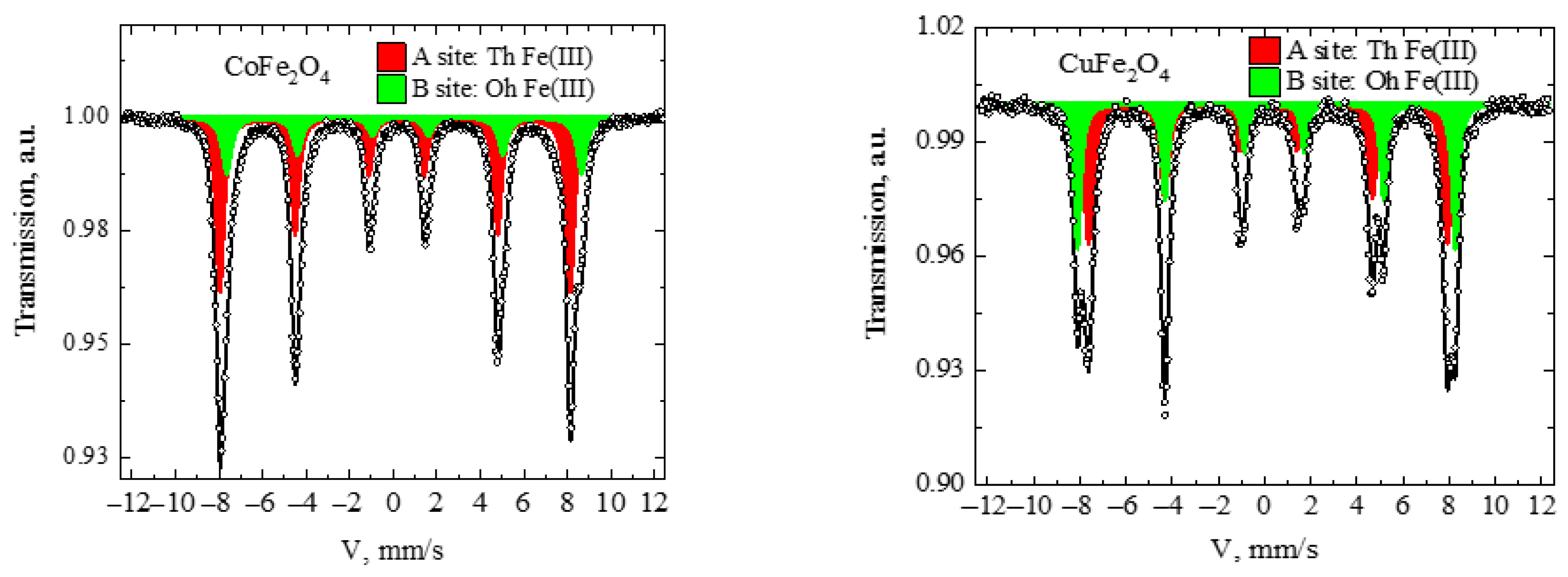
3.4. Mössbauer Spectroscopy

Mössbauer spectra of the cobalt and copper ferrites powders were typical for ferrite compounds (Figure 4 and Table 2). In agreement with the literature data [23,33,34], the spectrum of cobalt ferrite powder was fitted with two components: the first sextet had an isomer shift of 0.23 mm/s, quadrupole splitting of −0.05 mm/s, and hyperfine field of 498.8 kOe, corresponding to the high-spin Fe(III) in tetrahedral (Th) A site of spinel structure; the second sextet had an isomeric shift 0.52 mm/s, quadrupole splitting of 0.17 mm/s, and hyperfine field of 505.1 kOe, corresponding to the high-spin Fe(III) in octahedral (Oh) B site of spinel structure.
The spectrum of copper ferrite powder was fitted with two components: the first sextet had an isomer shift of 0.26 mm/s, quadrupole splitting of −0.02 mm/s, and hyperfine field of 481.7 kOe, corresponding to high-spin Fe(III) in tetrahedral A site of the spinel structure; the second sextet had an isomeric shift 0.36 mm/s, quadrupole splitting of −0.33 mm/s and hyperfine field of 507.6 kOe, corresponding to high-spin Fe(III) in octahedral B site of spinel structure.
For spinel ferrites, the general formula is (M2+1−xFe3+x)[M2+xFe3+2−x]O4 (cations in parentheses correspond to tetrahedral A sites, in square brackets to octahedral B sites), and x is the inversion parameter quantifying the distribution of M2+ and Fe3+ cations among these sites [35]. The relative area values of each component of the Mössbauer spectra general formula was calculated as (Co0.32Fe0.68)[Co0.68Fe1.32]O4 and (Cu0.38Fe0.62)[Cu0.62Fe1.38]O4 for cobalt and copper ferrites, respectively.

3.5. Indigo Carmine Degradation

Preliminary tests have shown that irradiation of indigo carmine (IC) solutions with natural pH = 4.6 does not lead to a noticeable dye decolorization in both UV and visible light. However, the decrease in IC solution pH to 2.9 facilitated dye decolorization in the presence of composite films. The absorption spectra of IC at pH 2.9 obtained before and after UV and visible irradiation are shown in Figure 5a. In the absence of catalyst (blank experiment), the IC degradation degree was insignificant and did not exceed 2, 5, and 13% after 3 h in darkness and exposure to visible and UV irradiation, respectively.
When the CuFe2O4-containing composites were used as photocatalysts, the IC degradation degree reached 74% and 45% under UV and visible irradiation, respectively. Composites containing CoFe2O4 showed a lower efficiency of IC degradation, which was ~59% under UV and 44% under visible light, respectively (Figure 5b). Thus, we concluded that the efficiency of IC photodegradation depended on both the pH of the solution and the type of ferrite.
A decrease in the IC solution pH affects both the surface charge of the coatings and the acid-base equilibrium of the IC in the aqueous solution. IC is an anionic dye, which exacts in the anionic form in the pH range of 3–11. The point of zero charge of CuFe2O4 and CoFe2O4 is 5.4 and 7.2, accordingly [36,37], while the surface of TiO2 is negatively charged at pH > 3 [38].
The acid-base properties of the surface coatings were studied by recording pH versus time curves in the absence and presence of samples after stabilization of the pH of distilled water. It can be seen from Figure 6 that the pH of water in the absence of samples does not change over time. In the presence of both samples, a gradual increase in water pH over time is observed. One can determine the pH value corresponding to the isoionic state of the surface from the equilibrium pH value. pH of the isoionic state was 5.58 and 5.6 for the CoFe2O4-PEO and CuFe2O4-PEO composites, respectively. An increase in water pH in the presence of composites over time indicates the predominance of basic Lewis sites on the surface, which form Bronsted acid sites after hydration. This process is accompanied by the release of the hydroxy groups into the water and, thus, an increase in pH. It can be assumed that the predominance of basic Lewis centers on the surface of the ferrite films prevents the attraction of negatively charged IC anions. Obviously, when the pH of the solution decreases, protonization of the basic Lewis centers increases, which promotes the interaction of the film surface with IC anions.
Therefore, at the pH of the solution below, three composite surfaces are positively charged due to protonation, indicating favorable conditions for interactions with anionic dye.
Since indigo carmine has pKa = 12.2, its amino groups are expected to be in the protonated form in acid media and the unprotonated form in highly alkaline media [39]. The negative charge of IC in an acidic medium comes from the S O 3 group. At pH < 3, sufficiently strong electrostatic interactions arise between the positively charged surface of TiO2-ferrite composites and IC anions, which leads to their strong adsorption on the surface. A noticeable decolorization of IC at a low pH results from the direct interaction of the dye molecule with the photocatalyst, which is necessary for the photocatalytic reaction to occur. A similar effect of the pH on the IC degradation was reported in [40,41,42].
The first-order kinetic equation was used o describe the degradation kinetics of IC under the action of UV and visible radiation for 180 min. The kinetic equation is expressed as:
L n C 0 C = k t ,
where C0 and C (mg/L) are the initial and final concentrations of IC in the solution, respectively; k is the IC degradation rate constant; and t is the reaction time (min). The Bouguer Lambert–Beer law establishes a relationship between the concentration of a solution and its optical density, expressed in the equation A = ε × b × C, where A, ε, b, and C are the absorbance of the solution, molar absorptivity, path length, and solution concentration, respectively. Therefore, the rate constant (k) can be determined graphically from the equation:
L n A 0 A = k t .
It is clearly seen that in all cases, ln(A0/A) linearly depends on time with the correlation coefficient (R2) > 0.99 (Figure 7 and Table 3). The calculated IC degradation rate constants are given in Table 3. In the absence of catalysts, the degradation rate of IC in both visible and UV light is much lower than in their presence. It can be seen from Table 3 that the CuFe2O4-PEO sample provides a higher rate of IC degradation than the CoFe2O4-PEO sample under the action of UV and visible radiation.
In order to give more insight into the photocatalytic activity of the samples, their optoelectronic properties were studied.

3.6. Optoelectronic Properties

The absorption spectrum fitting method with the Tauc model was utilized to estimate the optical band gap in PEO coatings containing cobalt and copper ferrites. To determine the optoelectronic properties of the synthesized samples, diffuse reflectance spectra (DRS) were taken in the range of 300–800 nm (Figure 8a). It is noticeable that the Ti/TiO2 (PEO) sample exhibits a unique spectrum for titanium dioxide and does not absorb within the λ = 400–800 nm region, which distinguishes it from the modified surface samples [43]. CuFe2O4-PEO and CoFe2O4-PEO samples exhibit a broad absorption peak within the λ = 400–800 nm range, indicating superior light absorption in the UV to visible range compared to Ti/TiO2. Therefore, these materials show high potential as photocatalysts with a wide range of applications.
Extrapolation of the linear part of the (αhν)2 curve to the (hν) axis showed that the energy of the direct allowed transition for the Ti/TiO2, CoFe2O4-PEO, and CuFe2O4-PEO sample is 3.11, 1.68, and 1.89 eV, respectively (Figure 8b). The value obtained for Ti/TiO2 corresponds to the literature data for titanium dioxide (~3.0 eV) [44]. According to [45,46,47], the value of the band gap for CoFe2O4 is ~1.4–1.76 eV, which correlates well with our results. For CuFe2O4, according to the literature data [48,49,50], the values range between 1.2 and 2.1 eV. Some discrepancies between the data obtained and the results of other authors may be associated with the complex compositional structure of the samples, leading to a shift in the edges of the valence and conduction bands.

3.7. Charge Carrier Mechanism

For a better understanding of the mechanism of charge carrier separation in titanium dioxide-based CoFe2O4 or CuFe2O4 composites, the potentials of the conduction (CB) and valence (VB) bands at the point of zero charge were calculated using Equations (5) and (6) [51]:
E V B = X E e + 1 2 E g ,
E C B = E V B E g ,
where Eg is the band gap; ECB is the conduction band potential; EVB is the valence band potential; X is the absolute electronegativity of the semiconductor, calculated as the geometric mean of the absolute electronegativity of the constituent atoms; and Ee is the energy of free electrons on the hydrogen scale (~4.5 eV) [52].
To calculate the parameters and plot the energy diagrams, the values of Eg for pure phases were taken from [53,54,55]. The calculated X, Eg, ECB, and EVB values for TiO2 and CoFe2O4/CuFe2O4 are presented in Table 4.
For a better understanding of the charge transfer process, an energy level diagram was plotted for individual semiconductors and formed heterostructures.
Figure 9a presents an energy diagram for a CoFe2O4-PEO sample. Before coupling, the Fermi level (Ef) of the TiO2 (n-type) semiconductor is closer to the edge of the conduction band (CB), and for CoFe2O4 (p-type) is closer to the valence band potential (VB) [56]. The CB potential of CoFe2O4 (−0.45 eV) is less negative than that of TiO2 (−0.25 eV), while the VB potential of TiO2 (+2.87 eV) is more positive than that of CoFe2O4 (+2.17 eV). After joining two semiconductors, Ef CoFe2O4 moves up, while Ef TiO2 moves down until Ef TiO2 and CoFe2O4 are aligned. Thus, a p-n heterojunction is formed at the interface between CoFe2O4 and TiO2. Because of the formation of the p-n heterojunction, the region close to the p–n interface is charged, creating an internal electric field. In this process, the TiO2 and CoFe2O4 bands bend, the overall energy level of CoFe2O4 increases, and the TiO2 level decreases [57]. For the CuFe2O4-PEO composite, the energy diagram has a similar form. Figure 9b shows that the VB CuFe2O4 edge (+2.37 eV) is much more positive than the VB TiO2 (+2.87 eV), while the CB CuFe2O4 potential (+0.33 eV) is positive and the CB TiO2 is negative (−0.25 eV). Under UV light irradiation, both TiO2 and CoFe2O4/CuFe2O4 can absorb photons giving rise to electrons and holes, whereas, under the action of visible light, the formation of photogenerated charges occurs only in CoFe2O4/CuFe2O4. However, we assume that the IC degradation mechanism was similar in both cases.
Because the position of CB CoFe2O4/CuFe2O4 is higher than that of TiO2, electrons can easily move from CB CoFe2O4/CuFe2O4 to CB TiO2. In turn, photogenerated holes can easily move from the higher VB TiO2 (+2.87 eV) to the lower VB CoFe2O4 (+2.17 eV). Therefore, the photogenerated holes and electrons can be separated effectively, which significantly enhances photocatalytic activity. Because the CB of both ferrites is more negative than O2/•O2 potential (−0.33 eV vs. NHE), photogenerated electrons can react with O2 to generate •O2 radicals, which are active species with strong oxidizing ability and can react with IC. Before the connection of two semiconductors, the valence band positions of CoFe2O4 (2.17 eV) and CuFe2O4 (2.37 eV) are more positive than the potential OH•/OH-(1.99 eV), indicating that •OH can be generated via the oxidation reaction of h+. Moreover, only ECB (CuFe2O4) is more positive than OH•/H2O (2.27 eV). This suggests that the formation of hydroxyl radicals in the composites with copper ferrite occurs more efficiently than in the composites based on cobalt ferrite. Therefore, IC can be degraded via the /•O2−, h+, or OH• oxidation pathway.
Therefore, based on the data given in the diagrams, it is impossible to give an unambiguous answer to the question of why copper ferrite is more active than cobalt ferrite. However, according to the literature, which describes other methods to determine the potentials of the valence band and the conduction band, CuFe2O4 has a more negative character of the conduction band (−1.1 eV), while cobalt ferrite is more positive (0.65 eV). According to [58], copper ferrite has a strong reduction ability, and cobalt ferrite has a moderate redox ability, which determines the higher photocatalytic activity of the first compared to the second. In [59], the authors also explained the higher photocatalytic activity of copper ferrite compared to nickel ferrite by the more negative nature of its conduction band.

4. Conclusions

In this paper, we reported a new method for the fabrication of cobalt and copper ferrite films on PEO coatings. The Fe:Cu/Co atomic ratios obtained by EDX analysis resulted in being close to 2:1. XRD patterns indicate the presence of cobalt and copper ferrite phases both in crystalline powders and in films on PEO-coatings. The Mössbauer spectra confirmed the structure of the obtained copper and cobalt ferrites: the presence of two sextet subspectra related to the tetrahedral Fe(III) A site and octahedral Fe(III) B site was determined. The photocatalytic properties of the obtained materials were demonstrated by the decomposition of indigo carmine (IC) as a model dye. It was shown that in the presence of CuFe2O4 -containing composite, the IC degradation degree reached 74% and 45% under UV and visible irradiation, respectively. While CoFe2O4 -containing composite provided IC degradation degrees of 59% and 44% under the same conditions, respectively. The high photocatalytic activity of the formed film composites is explained by the formation of p-n heterojunctions between TiO2 and CoFe2O4 (CuFe2O4), and pH dependence of IC degradation is determined by acid-base properties of the coatings promoting IC attraction in acidic medium.
In view of the simplicity, rapidity, and feasibility of scaling up, the proposed method of ferrite film composite fabrication is promising for the development of magnetic materials, sensors, catalysts, and photocatalysts.

Author Contributions

Conceptualization—D.B. and M.V.; investigation, D.B. and Y.B.; visualization, D.B. and Y.B.; writing—original draft preparation, D.B., Y.B. and M.V.; writing—review and editing, S.B.; resources, S.B. All authors have read and agreed to the published version of the manuscript.

Funding

This research was funded by the State Order of the Institute of Chemistry FEB RAS No. FWFN-2022-0002.

Data Availability Statement

Raw experimental data are available from the authors upon request.

Acknowledgments

XRD patterns were determined using equipment of the Far East Center of Structural Studies (Institute of Chemistry, FEB RAS, Vladivostok, Russia). The authors are thankful to A.V. Gerasimenko and D.H. Shlyk for the XRD analysis.

Conflicts of Interest

The authors declare no conflict of interest.

References

  1. Hazra, S.; Ghosh, N.N. Preparation of Nanoferrites and Their Applications. J. Nanosci. Nanotechnol. 2014, 14, 1983–2000. [Google Scholar] [CrossRef] [PubMed]
  2. Yanagihara, H.; Sharmin, S.; Niizeki, T.; Kita, E. Magnetic Properties of Spinel Ferrite Thin Films Grown by Reactive Sputtering. Mater. Trans. 2016, 57, 777–780. [Google Scholar] [CrossRef] [Green Version]
  3. Khairy, M.; Bayoumy, W.A.; Selima, S.S.; Mousa, M.A. Studies on Characterization, Magnetic and Electrochemical Properties of Nano-Size Pure and Mixed Ternary Transition Metal Ferrites Prepared by the Auto-Combustion Method. J. Mater. Res. 2020, 35, 2652–2663. [Google Scholar] [CrossRef]
  4. Du, H.; Akakuru, O.U.; Yao, C.; Yang, F.; Wu, A. Transition Metal Ion-Doped Ferrites Nanoparticles for Bioimaging and Cancer Therapy. Transl. Oncol. 2022, 15, 101264. [Google Scholar] [CrossRef]
  5. Tamboli, Q.Y.; Patange, S.M.; Mohanta, Y.K.; Sharma, R.; Zakde, K.R. Green Synthesis of Cobalt Ferrite Nanoparticles: An Emerging Material for Environmental and Biomedical Applications. J. Nanomater. 2023, 2023, 9770212. [Google Scholar] [CrossRef]
  6. Chen, H.D.; Xu, J.K.; Wei, J.Q.; Wang, P.F.; Han, Y.B.; Xu, J.C.; Hong, B.; Jin, H.X.; Jin, D.F.; Peng, X.L.; et al. Mesoporous CoFe2O4 Nanowires: Nanocasting Synthesis, Magnetic Separation and Enhanced Catalytic Degradation for Ciprofloxacin. J. Phys. Chem. Solids 2019, 132, 138–144. [Google Scholar] [CrossRef]
  7. Najwa, N.; Jani, M.; Rahmah, A.; Ahmad, D.; Adnan, R. CuFe2O4 as a Heterogeneous Fenton Catalyst for the Removal of Ciprofloxacin from Aqueous Solution at Natural PH. Malays. J. Catal. 2021, 5, 31–37. [Google Scholar]
  8. Swathi, S.; Yuvakkumar, R.; Kumar, P.S.; Ravi, G.; Velauthapillai, D. Annealing Temperature Effect on Cobalt Ferrite Nanoparticles for Photocatalytic Degradation. Chemosphere 2021, 281, 130903. [Google Scholar] [CrossRef]
  9. Zaharieva, K.; Rives, V.; Tsvetkov, M.; Cherkezova-Zheleva, Z.; Kunev, B.; Trujillano, R.; Mitov, I.; Milanova, M. Preparation, Characterization and Application of Nanosized Copper Ferrite Photocatalysts for Dye Degradation under UV Irradiation. Mater. Chem. Phys. 2015, 160, 271–278. [Google Scholar] [CrossRef]
  10. Motora, K.G.; Wu, C.M.; Naseem, S. Magnetic Recyclable Self-Floating Solar Light-Driven WO2.72/Fe3O4 Nanocomposites Immobilized by Janus Membrane for Photocatalysis of Inorganic and Organic Pollutants. J. Ind. Eng. Chem. 2021, 102, 25–34. [Google Scholar] [CrossRef]
  11. Li, K.; Zhong, Y.; Luo, S.; Deng, W. Fabrication of Powder and Modular H3PW12O40/Ag3PO4 Composites: Novel Visible-Light Photocatalysts for Ultra-Fast Degradation of Organic Pollutants in Water. Appl. Catal. B Environ. 2020, 278, 119313. [Google Scholar] [CrossRef]
  12. Tao, W.; Wang, M.; Ali, R.; Nie, S.; Zeng, Q.; Yang, R.; Lau, W.M.; He, L.; Tang, H.; Jian, X. Multi-Layered Porous Hierarchical TiO2/g-C3N4 Hybrid Coating for Enhanced Visible Light Photocatalysis. Appl. Surf. Sci. 2019, 495, 143435. [Google Scholar] [CrossRef]
  13. Li, X.; Wu, X.; Xue, W.; Cheng, G.; Zheng, R.; Cheng, Y. Structures and Properties of Ceramic Films on TiAl Intermetallic Compound Fabricated by Microarc Oxidation. Surf. Coat. Technol. 2007, 201, 5556–5559. [Google Scholar] [CrossRef]
  14. Terleeva, O.P.; Belevantsev, V.I.; Slonova, A.I.; Boguta, D.L.; Rudnev, V.S. Comparison Analysis of Formation and Some Characteristics of Microplasma Coatings on Aluminum and Titanium Alloys. Prot. Met. 2006, 42, 272–278. [Google Scholar] [CrossRef]
  15. Wang, Y.; Jiang, B.; Lei, T.; Guo, L. Dependence of Growth Features of Microarc Oxidation Coatings of Titanium Alloy on Control Modes of Alternate Pulse. Mater. Lett. 2004, 58, 1907–1911. [Google Scholar] [CrossRef]
  16. Zhang, W.; Du, K.; Yan, C.; Wang, F. Preparation and Characterization of a Novel Si-Incorporated Ceramic Film on Pure Titanium by Plasma Electrolytic Oxidation. Appl. Surf. Sci. 2008, 254, 5216–5223. [Google Scholar] [CrossRef]
  17. Rudnev, V.S.; Yu Ustinov, A.; Lukiyanchuk, I.V.; Kharitonskii, P.V.; Frolov, A.M.; Morozova, V.P.; Tkachenko, I.A.; Sergienko, A.V.I. Magnetic Properties of Plasma Electrolytic Iron-Containing Oxide Coatings on Aluminum. Dokl. Phys. Chem. 2009, 428, 189–192. [Google Scholar] [CrossRef]
  18. Hoseini, A.; Yarmand, B. Immobilization of Fe2O3/TiO2 Photocatalyst on the Metallic Substrate via Plasma Electrolytic Oxidation Process: Degradation Efficiency. J. Nanopart. Res. 2020, 22, 312. [Google Scholar] [CrossRef]
  19. Kim, Y.S.; Shin, K.R.; Kim, G.W.; Ko, Y.G.; Shin, D.H. Photocatalytic Activity of TiO2 Film Containing Fe2O3 via Plasma Electrolytic Oxidation. Surf. Eng. 2016, 32, 443–447. [Google Scholar] [CrossRef]
  20. Tang, X.; Jin, L.; Wei, R.; Zhu, X.; Yang, J.; Dai, J.; Song, W.; Zhu, X.; Sun, Y. High-Coercivity CoFe2O4 Thin Films on Si Substrates by Sol-Gel. J. Magn. Magn. Mater. 2017, 422, 255–261. [Google Scholar] [CrossRef]
  21. Wang, X.W.; Zhang, Y.Q.; Meng, H.; Wang, Z.J.; Zhang, Z.D. Perpendicular Magnetic Anisotropy in 70 nm CoFe2O4 Thin Films Fabricated on SiO2/Si(100) by the Sol–Gel Method. J. Alloys Compd. 2011, 509, 7803–7807. [Google Scholar] [CrossRef]
  22. Shi, M.; Zuo, R.; Xu, Y.; Jiang, Y.; Yu, G.; Su, H.; Zhong, J. Preparation and Characterization of CoFe2O4 Powders and Films via the Sol–Gel Method. J. Alloys Compd. 2012, 512, 165–170. [Google Scholar] [CrossRef]
  23. Ferreira, L.S.; Silva, T.R.; Santos, J.R.D.; Silva, V.D.; Raimundo, R.A.; Morales, M.A.; Macedo, D.A. Structure, Magnetic Behavior and OER Activity of CoFe2O4 Powders Obtained Using Agar-Agar from Red Seaweed (Rhodophyta). Mater. Chem. Phys. 2019, 237, 121847. [Google Scholar] [CrossRef]
  24. Grilikhes, S.Y. Metal Degreasing, Etching and Polishing; Mashinostroenie: Leningrad, Russia, 1977. [Google Scholar]
  25. Vasil’eva, M.S.; Rudnev, V.S.; Sklyarenko, O.E.; Tyrina, L.M.; Kondrikov, N.B. Titanium-Supported Nickel-Copper Oxide Catalysts for Oxidation of Carbon(II) Oxide. Russ. J. Gen. Chem. 2010, 80, 1557–1562. [Google Scholar] [CrossRef]
  26. Zi, Z.; Sun, Y.; Zhu, X.; Yang, Z.; Dai, J.; Song, W. Synthesis and Magnetic Properties of CoFe2O4 Ferrite Nanoparticles. J. Magn. Magn. Mater. 2009, 321, 1251–1255. [Google Scholar] [CrossRef]
  27. Wang, W.H.; Ren, X. Flux Growth of High-Quality CoFe2O4 Single Crystals and Their Characterization. J. Cryst. Growth 2006, 289, 605–608. [Google Scholar] [CrossRef]
  28. Jiang, J.Z.; Goya, G.F.; Rechenberg, H.R. Magnetic Properties of Nanostructured CuFe2O4. J. Phys. Condens. Matter 1999, 11, 4063–4078. [Google Scholar] [CrossRef] [Green Version]
  29. Sun, Z.; Liu, L.; Jia, D.Z.; Pan, W. Simple Synthesis of CuFe2O4 Nanoparticles as Gas-Sensing Materials. Sens. Actuators B Chem. 2007, 125, 144–148. [Google Scholar] [CrossRef]
  30. Lukiyanchuk, I.V.; Vasilyeva, M.S.; Sergeev, A.A.; Nepomnyashchii, A.V.; Serov, M.M.; Krit, B.L. Features of Coalescence of Gold on the Surface of Different Supports during Catalytic Oxidation of CO. Prot. Met. Phys. Chem. Surf. 2021, 57, 1172–1179. [Google Scholar] [CrossRef]
  31. Joni, I.M.; Nulhakim, L.; Vanitha, M.; Panatarani, C. Characteristics of Crystalline Silica (SiO2) Particles Prepared by Simple Solution Method Using Sodium Silicate (Na2SiO3) Precursor. J. Phys. Conf. Ser. 2018, 1080, 012006. [Google Scholar] [CrossRef]
  32. Vasilyeva, M.S.; Lukiyanchuk, I.V.; Sergeev, A.A.; Sergeeva, K.A.; Ustinov, A.Y.; Tkachev, V.V.; Arefieva, O.D. Plasma Electrolytic Synthesis and Characterization of Oxide Coatings with MWO4 (M = Co, Ni, Cu) as Photo-Fenton Heterogeneous Catalysts. Surf. Coat. Technol. 2021, 424, 127640. [Google Scholar] [CrossRef]
  33. Agouriane, E.; Rabi, B.; Essoumhi, A.; Razouk, A.; Sahlaoui, M.; Costa, B.F.O.; Sajieddine, M. Structural and Magnetic Properties of CuFe2O4 Ferrite Nanoparticles Synthesized by Co-Precipitation. J. Mater. Environ. Sci. 2016, 7, 4116–4120. [Google Scholar]
  34. Grigorova, M.; Blythe, H.J.; Blaskov, V.; Rusanov, V.; Petkov, V.; Masheva, V.; Nihtianova, D.; Martinez, L.M.; Muñoz, J.S.; Mikhov, M. Magnetic Properties and Mössbauer Spectra of Nanosized CoFe2O4 Powders. J. Magn. Magn. Mater. 1998, 183, 163–172. [Google Scholar] [CrossRef]
  35. Sanchez-Lievanos, K.R.; Stair, J.L.; Knowles, K.E. Cation Distribution in Spinel Ferrite Nanocrystals: Characterization, Impact on Their Physical Properties, and Opportunities for Synthetic Control. Inorg. Chem. 2021, 60, 4291–4305. [Google Scholar] [CrossRef] [PubMed]
  36. Kosmulski, M. Compilation of PZC and IEP of Sparingly Soluble Metal Oxides and Hydroxides from Literature. Adv. Colloid Interface Sci. 2009, 152, 14–25. [Google Scholar] [CrossRef]
  37. Vergis, B.R.; Hari Krishna, R.; Kottam, N.; Nagabhushana, B.M.; Sharath, R.; Darukaprasad, B. Removal of Malachite Green from Aqueous Solution by Magnetic CuFe2O4 Nano-Adsorbent Synthesized by One Pot Solution Combustion Method. J. Nanostructure Chem. 2017, 8, 1–12. [Google Scholar] [CrossRef] [Green Version]
  38. Kosmulski, M. PH-Dependent Surface Charging and Points of Zero Charge II. Update. J. Colloid Interface Sci. 2004, 275, 214–224. [Google Scholar] [CrossRef]
  39. Ammar, S.; Abdelhedi, R.; Flox, C.; Arias, C.; Brillas, E. Electrochemical Degradation of the Dye Indigo Carmine at Boron-Doped Diamond Anode for Wastewaters Remediation. Environ. Chem. Lett. 2006, 4, 229–233. [Google Scholar] [CrossRef]
  40. Othman, I.; Mohamed, R.M.; Ibrahem, F.M. Study of Photocatalytic Oxidation of Indigo Carmine Dye on Mn-Supported TiO2. J. Photochem. Photobiol. A Chem. 2007, 189, 80–85. [Google Scholar] [CrossRef]
  41. Barka, N.; Assabbane, A.; Nounah, A.; Ichou, Y.A. Photocatalytic Degradation of Indigo Carmine in Aqueous Solution by TiO2-Coated Non-Woven Fibres. J. Hazard. Mater. 2008, 152, 1054–1059. [Google Scholar] [CrossRef]
  42. Vasilyeva, M.S.; Lukiyanchuk, I.V.; Sergeev, A.A.; Ustinov, A.Y.; Sergeeva, K.A.; Kuryavyi, V.G. Ti/TiO2-CoWO4-Co3(PO4)2 Composites: Plasma Electrolytic Synthesis, Optoelectronic Properties, and Solar Light-Driven Photocatalytic Activity. J. Alloys Compd. 2021, 863, 158066. [Google Scholar] [CrossRef]
  43. Padmanabhan, S.K.; Pal, S.; Ul Haq, E.; Licciulli, A. Nanocrystalline TiO2–Diatomite Composite Catalysts: Effect of Crystallization on the Photocatalytic Degradation of Rhodamine B. Appl. Catal. A Gen. 2014, 485, 157–162. [Google Scholar] [CrossRef]
  44. Daude, N.; Gout, C.; Jouanin, C. Electronic Band Structure of Titanium Dioxide. Phys. Rev. B 1977, 15, 3229–3235. [Google Scholar] [CrossRef]
  45. Sonu; Dutta, V.; Sharma, S.; Raizada, P.; Hosseini-Bandegharaei, A.; Gupta, V.K.; Singh, P. Review on Augmentation in Photocatalytic Activity of CoFe2O4 via Heterojunction Formation for Photocatalysis of Organic Pollutants in Water. J. Saudi Chem. Soc. 2019, 23, 1119–1136. [Google Scholar] [CrossRef]
  46. Syed, A.; Ahmed, B.; Elgorban, A.M.; Bahkali, A.H.; Lee, J.; Rajput, V.D.; Minkina, T. Designing Spinel CoFe2O4 Loaded Sheet-like Bi2O3 Nano-Heterostructure for Synergetic White-Light Photocatalysis with Recombination Delay and Antibacterial Applications. Colloids Surf. A Physicochem. Eng. Asp. 2021, 629, 127449. [Google Scholar] [CrossRef]
  47. Jia, Y.; Ma, H.; Liu, C. Au Nanoparticles Enhanced Z-Scheme Au-CoFe2O4/MoS2 Visible Light Photocatalyst with Magnetic Retrievability. Appl. Surf. Sci. 2019, 463, 854–862. [Google Scholar] [CrossRef]
  48. Zhao, W.; Jin, Y.; Gao, C.H.; Gu, W.; Jin, Z.M.; Lei, Y.L.; Liao, L.S. A Simple Method for Fabricating p–n Junction Photocatalyst CuFe2O4/Bi4Ti3O12 and Its Photocatalytic Activity. Mater. Chem. Phys. 2014, 143, 952–962. [Google Scholar] [CrossRef]
  49. Sonu; Dutta, V.; Sudhaik, A.; Khan, A.A.P.; Ahamad, T.; Raizada, P.; Thakur, S.; Asiri, A.M.; Singh, P. GCN/CuFe2O4/SiO2 Photocatalyst for Photo-Fenton Assisted Degradation of Organic Dyes. Mater. Res. Bull. 2023, 164, 112238. [Google Scholar] [CrossRef]
  50. Wei, X.; Yang, X.; Xu, X.; Liu, Z.; Naraginti, S.; Wan, J. Novel Magnetically Separable Tetrahedral Ag3PO4/NrGO/CuFe2O4 Photocatalyst for Efficient Detoxification of 2,4-Dichlorophenol. Environ. Res. 2021, 201, 111519. [Google Scholar] [CrossRef]
  51. Chang, N.; Chen, Y.R.; Xie, F.; Liu, Y.P.; Wang, H.T. Facile Construction of Z-Scheme AgCl/Ag-Doped-ZIF-8 Heterojunction with Narrow Band Gaps for Efficient Visible-Light Photocatalysis. Colloids Surf. A Physicochem. Eng. Asp. 2021, 616, 126351. [Google Scholar] [CrossRef]
  52. Yuan, Q.; Chen, L.; Xiong, M.; He, J.; Luo, S.L.; Au, C.T.; Yin, S.F. Cu2O/BiVO4 Heterostructures: Synthesis and Application in Simultaneous Photocatalytic Oxidation of Organic Dyes and Reduction of Cr(VI) under Visible Light. Chem. Eng. J. 2014, 255, 394–402. [Google Scholar] [CrossRef]
  53. Steblevskaya, N.I.; Medkov, M.A.; Belobeletskaya, M.V. The Use of the Extraction–Pyrolytic Method for the Production of Oxide Functional Films and Coatings. Theor. Found. Chem. Eng. 2022, 56, 934–941. [Google Scholar] [CrossRef]
  54. Lubis, S.; Sheilatina; Murisna. Synthesis, Characterization and Photocatalytic Activity of α-Fe2O3/Bentonite Composite Prepared by Mechanical Milling. J. Phys. Conf. Ser. 2018, 1116, 042016. [Google Scholar] [CrossRef]
  55. Nawle, A.C.; Humbe, A.V.; Babrekar, M.K.; Deshmukh, S.S.; Jadhav, K.M. Deposition, Characterization, Magnetic and Optical Properties of Zn Doped CuFe2O4 Thin Films. J. Alloys Compd. 2017, 695, 1573–1582. [Google Scholar] [CrossRef]
  56. Zhang, Y.; Schultz, A.M.; Salvador, P.A.; Rohrer, G.S. Spatially Selective Visible Light Photocatalytic Activity of TiO2/BiFeO3 Heterostructures. J. Mater. Chem. 2011, 21, 4168. [Google Scholar] [CrossRef]
  57. Humayun, M.; Zada, A.; Li, Z.; Xie, M.; Zhang, X.; Qu, Y.; Raziq, F.; Jing, L. Enhanced Visible-Light Activities of Porous BiFeO3 by Coupling with Nanocrystalline TiO2 and Mechanism. Appl. Catal. B Environ. 2016, 180, 219–226. [Google Scholar] [CrossRef]
  58. Mishra, S.; Acharya, R.; Parida, K. Spinel-Ferrite-Decorated Graphene-Based Nanocomposites for Enhanced Photocatalytic Detoxification of Organic Dyes in Aqueous Medium: A Review. Water 2022, 15, 81. [Google Scholar] [CrossRef]
  59. Soto-Arreola, A.; Huerta-Flores, A.M.; Mora-Hernández, J.M.; Torres-Martínez, L.M. Comparative Study of the Photocatalytic Activity for Hydrogen Evolution of MFe2O4 (M = Cu, Ni) Prepared by Three Different Methods. J. Photochem. Photobiol. A Chem. 2018, 357, 20–29. [Google Scholar] [CrossRef]
Figure 1. Stages of fabrication cobalt and copper ferrites films on the PEO-coatings.
Jcs 07 00295 g001
Figure 2. SEM images and EDX maps of Co- (a) and Cu- (b) ferrites powders and Co- (c) and Cu- (d) ferrites films on the PEO-coatings.
Jcs 07 00295 g002aJcs 07 00295 g002b
Figure 3. X-ray diffraction patterns of (a) Co-, Cu- ferrites powders, and (b) Co- and Cu- ferrite films on the PEO-coatings.
Jcs 07 00295 g003
Figure 4. Mössbauer spectra of Co- and Cu- ferrites powders: dots are experimental data; lines are spectra fits obtained with the WinNormos program (Th—tetrahedral, Oh—octahedral).
Jcs 07 00295 g004
Figure 5. Absorption spectra of IC (a) and corresponding dye degradation degree (b) for the photocatalytic degradation of IC using CuFe2O4-PEO and CoFe2O4-PEO under UV and visible (VIS) light irradiation at pH 2.9.
Jcs 07 00295 g005
Figure 6. Time-dependent evolution of water pH in the absence and presence of CuFe2O4-PEO and CoFe2O4-PEO composites.
Jcs 07 00295 g006
Figure 7. Time-dependent degradation of IC under UV and visible light in the presence of PEO-coated samples and without them (blank experiment).
Jcs 07 00295 g007
Figure 8. UV–visible diffuse reflectance spectra in absorbance scale (a) and plot of (αhν)2 versus energy (eV) (b) to determine the band gap for a direct allowed transition of PEO-coatings containing cobalt and copper ferrites; dotted lines are linear approximations.
Jcs 07 00295 g008
Figure 9. Energy diagrams and the proposed mechanism of the photocatalytic IC degradation over (a) CoFe2O4-PEO and (b) CuFe2O4-PEO composites under UV irradiation.
Jcs 07 00295 g009
Table 1. Elemental analysis of Co- and Cu- ferrites as powders and films on the PEO-coatings.
SampleAtomic Ratios in Samples
Fe:Cu/Co
Cu/Co, at %Fe, at %O, at %Ti, at %Si, at %
CoFe2O42:1.1517.6430.7551.60
CuFe2O42:1.0716.1630.0953.74
CoFe2O4-PEO2:1.012.985.9364.406.0020.69
CuFe2O4-PEO2:1.042.434.6666.316.6719.93
Table 2. Mossbauer parameters for Co- and Cu- ferrites powders, T = 298 K *.
Sampleδ, mm/sΔ, mm/sH, kOeΓ, mm/sRelative area, %Assignment
CoFe2O40.23−0.05498.80.4567.73A site: Th Fe(III)
0.520.17505.10.5132.27B site: Oh Fe(III)
CuFe2O40.26−0.02481.70.4761.58A site: Th Fe(III)
0.36−0.33507.60.3738.42B site: Oh Fe(III)
* Isomer shift (δ), quadrupole splitting (Δ), hyperfine field (H), linewidth (Γ). Values of δ are reported relative to α-Fe metal. Fitting error in the values of δ, Δ, and Γ remained below 0.01 mm/s.
Table 3. Degradation rate constants (k) and correlation coefficients (R2) for IC degradation under UV and VIS irradiation.
SampleUVVIS
k, min−1R2k, min−1R2
Blank IC0.57 × 10−30.990.41 × 10−30.99
CoFe2O4-PEO5.00 × 10−30.993.02 × 10−30.99
CuFe2O4-PEO7.97 × 10−30.993.60 × 10−30.99
Table 4. Values of Mulliken semiconductor electronegativity X, band gap energy Eg, conduction band bottom ECB, and valence band top EVB for individual components of the formed heterostructures.
SampleX, eVEg, eV (Ref)ECB, eVEVB, eV
TiO25.813.11 [53]−0.252.87
CoFe2O45.811.72 [54]−0.452.17
CuFe2O45.852.04 [55]−0.332.37
Disclaimer/Publisher’s Note: The statements, opinions and data contained in all publications are solely those of the individual author(s) and contributor(s) and not of MDPI and/or the editor(s). MDPI and/or the editor(s) disclaim responsibility for any injury to people or property resulting from any ideas, methods, instructions or products referred to in the content.

