
Heterogeneous Hierarchical Self-Assembly Forming Crystalline Nanocellulose–CaCO3 Hybrid Nanoparticle Biocomposites

1
Department of Bioproducts and Biosystems, School of Chemical Engineering, Aalto University, 00076 Espoo, Finland
2
Department of Chemical and Metallurgical Engineering, School of Chemical Engineering, Aalto University, 00076 Espoo, Finland
3
Faculty of Technology and Metallurgy, University of Belgrade, Karnegijeva 4, 11200 Belgrade, Serbia
*
Author to whom correspondence should be addressed.
J. Compos. Sci. 2023, 7(8), 333; https://doi.org/10.3390/jcs7080333
Submission received: 15 July 2023
/
Revised: 1 August 2023
/
Accepted: 7 August 2023
/
Published: 16 August 2023
(This article belongs to the Special Issue Performance Enhancement of Advanced Composites and Biobased Composites through Hybrid Approach, Volume II)
Abstract
:Nanocellulose is increasingly proposed as a sustainable raw material having strong interparticle bonding. However, cellulose alone has limited bending and impact resistance. We newly observe self-assembly between crystalline nanocellulose (CNC) and ultrafine ground chemical-free calcium carbonate nanoparticles (UGCC). The suspension displays an intrinsic gel-like state, and heterogeneous adsorption occurs under the specific conditions where Brownian motion of both species is arrested by application of ultralow shear (0.01 s−1). In contrast, simple static aging of the mixture leads to autoflocculation of each species independently. The heterogeneous adsorption results in compound particle self-assembly leading to multi-level hierarchical structures depending on relative species size and concentration ratio. Fine particles from species 1 adsorb onto the coarser complementary particles of species 2 and vice versa. Depending also on whether CNC or UGCC particles are in excess, the structural assembly occurs primarily through either CNC–CNC hydrogen bonding or CaCO3–CaCO3 autogenous flocculation, respectively. Controlling the hierarchical composite structure bonding in this way, the resulting morphology can express dual or predominantly single either mineralic or cellulosic surface properties. Novel complex hybrid biocomposite materials can therefore be produced having designable compatibility across a broad range of both natural and oil-based polymeric materials. Both CNC and UGCC are exemplified here via commercial products.
1. Introduction
The development of biobased multifunctional materials is inspired by the many extraordinary properties of biological composites, such as bone, nacre, and eggshell. These nanocomposites in nature, comprising high surface area nanoscale constituents, have unique optical properties and mechanical toughness, whilst retaining insensitivity to flow (Osong et al., 2015) [1]. Similarly, biomaterial composites made from nanocellulose and calcium carbonate can combine impressive properties following environmentally friendly production routes (Rantanen et al., 2015) [2]. Crystalline nanocellulose (CNC) is the basic building unit of cellulose polymer constituting wood and biomass fiber, being combined with amorphous cellulose phases in the natural product. The crystalline fraction can be isolated using acid hydrolysis of such fibers, displaying large transverse and axial Young’s moduli and superiority to regular cellulose microfibers (CMF), and it can even exceed those of Kevlar, making it a highly attractive material for use as a reinforcement in biobased composites (Zhou et al., 2012; Moud et al., 2022) [3,4]. Advanced applications can include various fields such as transparent films (Le and Wang, 2014) [5], pharmaceuticals, and electronics (Shankaran, 2018) [6].
Aqueous colloid applications of micro- and nanocellulose are found increasingly in systems used for mineral beneficiation, typically in flotation. The greatest benefit is that cellulose can be considered environmentally harmless compared with synthetic flotation aids, including surfactants, which are often combined with hydrophobizing agents. Pioneering work in this area has been reported by Hartmann et al. and Bendersky et al. (Hartmann et al., 2018; Hartmann et al., 2021; Bendersky et al., 2015) [7,8,9], supported by an understanding of the suspension stability characteristics of nanocellulose (Hubbe and Rojas, 2008) [10]. However, the interaction in these cases is based mainly on electrostatic or hydrophobic attraction rather than reactive adsorption. Nanocellulose has also been identified as a useful component in general bionanocomposites, as reviewed by Siqueira et al. (Siqueira et al., 2010; Siró and Plackett, 2010) [11,12], focusing mainly on addition to non-aqueous traditional fossil oil-based polymeric systems.
In parallel, calcium carbonate is the major biomineral found in many natural nanocomposites, such as mussel shells, exoskeletons of corals and algae, and the carapaces of crayfish and lobsters. It is also produced in large quantities as an important industrial resource, utilized as pigment for filler or coating in paper, paint, and plastics, as well as in advanced applications, such as pharmaceutical tableting, antacids, nutraceutical delivery, environmental soil enhancers, and urease-aided mineralization (Ambrogi, 2023; Watcharamul et al., 2022) [13,14]. Calcium carbonate also has an interesting double role within potable water systems, due to its scaling and self-regeneration effects (Osong et al., 2015; Schenker et al., 2015; Krajewska, 2018) [1,15,16]. Due to its complex thermal sensitivity to dissolution and pH, global warming may affect its equilibrium behavior in natural systems in the future (Richards et al., 2018) [17], making it an ideal environmentally reactive composite component.
Sulfuric acid is frequently used to produce CNC from a number of different sources of cellulose, including plants, bacteria, and some sea creatures (tunicates) (Habibi et al., 2010; Klemm et al., 2011) [18,19]. During hydrolysis, charged sulfate half-ester groups are created on the rod-like CNC surface, and the resultant electrostatic repulsion between individual nanocrystals keeps the CNC well dispersed in water, hence producing a stable colloidal dispersion of nanoparticles. Above a critical CNC concentration, this dispersion separates spontaneously into an isotropic phase and an anisotropic chiral nematic (cholesteric) liquid crystalline phase (Revol et al., 1992; Majoinen, 2012; Wang et al., 2020) [20,21,22], generating a gel-like suspension consistency. CNC dispersions remain stable in deionized water and in NaCl brine, even when subjected to variations in pH within the range 5–9 (Dimic-Misic et al., 2015) [23]. Also, temperature within the range 50 to 90 °C causes degradation of neither the material nor its dispersion stability. However, extended heat aging at 90 °C and 120 °C for seven days eventually leads to suspension viscosity increase and pH decrease, both of which are considered an indication of the degradation of CNC dispersions (Molnes et al., 2017) [24]. A further advantage of considering inclusion of CaCO3 in combination is that, in aqueous suspension, it can dissociate partly into the acid salt, and so further, with CO2 release, providing a strong buffering capacity against acid.
The shorter rod-like crystalline nanocellulose (CNC), prepared from various cellulosic starting materials via strong acid hydrolysis, enables precise structural control in suspension; for example, liquid crystalline packing in solvent media, patterning for chirality, and in nanocomposites (Dimic-Misic et al., 2015) [25]. Orientation of the anisotropic CNC particles in liquid crystalline order during their processing are expected to improve the mechanical properties of the resulting composites. Several CNC-reinforced nanocomposite structures have been prepared by adding a small weight fraction of well-dispersed CNC in elastomeric or polymeric matrices, as reported by (Koshkava and Kamal, 2015) [26].
Currently, the target to include idealized CNC and utilize them in technologically feasible ways is a major research topic. In addition, native fibrillar nanocellulosic materials have received considerable emphasis in materials research due to their abundance, sustainability, and mechanical strength properties. There remain challenges; the hygroscopic nature of CNC leads to reduced thermal resistivity and high sensitivity to moisture in composite form, resulting in practical environmental limitations in mechanical properties of CNC-containing composites. In addition, to overcome their hydrophilicity, a variety of chemical and physical modification routes have been suggested for CNCs to promote their compatibility with nonpolar polymer matrix composites. Application of CNC and calcium carbonate suspensions could, therefore, allow production of mechanically advanced biomaterial hybrid nanocomposites adopting self-assembly structural properties. Considering the numerous applications where micro nanofibrillated cellulose (MNFC) is mixed with calcium carbonate, the rod-like CNC nanomaterials in contrast could in turn create higher-performing material properties when used as a reinforcement (Chaari et al., 2003; Spicer et al., 1998) [27,28]. Here, we explore such a concept with respect to adsorption of polyelectrolyte-free CaCO3 filler particles leading to structuration and eventual dewatering of CNC gel suspensions. The concept of promoting the interaction central to the heterogeneous adsorption follows the original work of Liu et al., 2017 (Liu et al., 2017) [29], which was applied to MNFC rather than CNC, where the concept of arresting Brownian motion in the suspension gel, by inducing stress below the yield point, was first shown to provide sufficient contact time between the species such that the calcium carbonate particles undergo ion exchange at the nanofibril surface and then autoflocculate while attached to the nanofibrils of the MNFC.
Adsorption and subsequent flocculation via the adsorbate(s) is a complex process. In typical industrial applications, this is achieved with chemical additives, which act to coagulate or flocculate, depending on their nature, requiring mixing control (Martoïa et al., 2015) [30]. Using such flocculants, the aggregation of the fine particles into flocs is defined initially by colloidal destabilization, or particle bridging adsorption, and subsequent growth of flocs, which develop due to inherent particle–particle attraction or by water-solvent exclusion from the surrounding medium during collisions within the system (Hogg, 2000) [31]. The weak structure associated with flocculation differs from agglomeration and final aggregation. Flocs can, eventually, be readily redispersed, when placed under high shear (Spicer et al., 1998; Tiller et al., 1987; Dentel et al., 2000) [28,32,33], whereas aggregates, in contrast, arise from strong bonding via van der Waals forces upon intimate contact, or ion-exchange reactions, leading in some cases to interparticle crystallization. In the case of autoflocculation, the formation of the flocs occurs between particles of the same species due to the removal or non-existence of any form of colloidal stabilization (Hogg, 2000) [31]. Therefore, such mechanisms, which can be inherently triggered via application of ultralow shear over an extended timescale to non-stabilized colloidal mineral particles, offer an opportunity to initiate matrix autoflocculation in a variety of systems: one example of this is flocculation of sediments in water (Savage and Diallo, 2005; O’Melia, 1998) [34,35]. In contrast, the interesting challenge we undertake here is to initiate prior adsorption between minerals and the crystalline cellulose species in the dispersed CNC–gel matrix without the use of chemical additives.
The previous work on calcium carbonate adsorption onto cellulose, mentioned above, concerned the specific case of micro nanofibrillated cellulose (MNFC) systems (Liu et al., 2017) [29], which contained both larger microfibrils and nanofibrils, the latter associated directly with the microfibril surface. Choosing calcium carbonate as the likely optimal mineral particle relies, as in the previous work, on its ability to dissociate and so supply Ca2+ ions, which can drive heterogeneous adsorption in the presence of the available cellulose surface water layer providing the opportunity for proton exchange. This behavior, accompanied with likely shear banding within the gel suspension, was seen to lead to phase separation within the MNFC–gel matrix, exhibiting a layer of water above the autoflocculated composite formed. Structuration in that case was predominantly via calcium carbonate particle autoflocculation whilst attached to the cellulose fibrils, perhaps aided to some extent by the opportunity to form entanglement between the larger fibrils.
In our present study, the mineral particles and the CNC particles are of similar ultrafine size, such that the adsorption can be heterogeneously distributed, either calcium carbonate adsorbing to cellulose crystals or vice versa, such that the mineral particles, if in excess on the composite surface, subsequently can initiate polyectrolyte-free autoflocculation, or hydrogen bonding between cellulose particles can occur if CNC is in excess. Thus, structuring the complete cellulose–calcium carbonate composite can follow hybridization via one of the two mechanisms, or a combination of both. The target here is, therefore, to see if the crystalline CNC interacts with CaCO3 particles in a similarly controlled way, without the previously added role of larger microfibers. The balance between particle Brownian motion and the time of contact between dispersant-free ground calcium carbonate (UGCC) particles and CNC will once again be extended by immobilizing under ultralow shear strain. Finally, we show that both subsequent autoflocculation between the CaCO3 particles and hydrogen bonding between cellulose particles can provide complementary desired composite structuration with associated dewatering. The value of producing this hybrid biocomposite is that not only can heterogeneous self-assembly be employed as a steering mechanism in its production, but the designable dual nature of the composite potentially allows further processing and application either as functional additive into novel cellulose and other biopolymer systems, or, following suitable surface aliphatic treatment of the calcium carbonate exposed surface, could be applied in standard oleophilic polymer composite systems, thus avoiding the typical incompatibility of trying to introduce sustainable cellulose species into such systems. The aim in these cases is to enhance polymer strength, stiffness, and impact resistance.
2. Materials and Methods
2.1. Cellulose Nanocrystals
The highly crystalline rod-like CNC in this study was of industrially produced quality from Melodea Ltd., Rehovot, HaMerkaz, Israel, which uses recycled cellulose as raw material. After sonication, the CNC suspension had a solids content of 3 w/w%.
Scanning electron microscope (SEM) imaging (Hitachi S-4700, Chiyoda City, Tokyo, Japan), Figure 1, was made from chiral nematic films cast from cellulose nanocrystal suspensions. Before imaging, the sample suspensions were freeze-dried by placing them in liquid nitrogen prior to sublimation under vacuum.
2.2. Dispersant-Free Ground Calcium Carbonate (UGCC)
The mineral material for these studies was undispersed (no dispersing agent) ground calcium carbonate (UGCC) (Covercarb® 60-ME prior to product dispersion from Omya Hustadmarmor AS, Elnesvågen, Norway), presenting a typical high light scattering, narrow particle size distribution marble pigment (nominally 60 w/w% < 1 μm) utilized mainly in paper and board production. The ground mineral paste was obtained with a solid content of 62 w/w%. For stock suspensions, we prepared diluted UGCC suspensions with 20 w/w% and 8 w/w% solids content.
2.3. Preparation of CNC and UGCC Composite Suspensions
Samples were prepared to determine agglomeration phenomena and to observe the agglomeration of suspensions in the static and dynamic shear states following the formulation principles described by Dimic-Misic et al. (Dimic-Misic et al., 2017) [36]. These properties are important to compare with the observations of phase separation of the differentially flocculated micro-nanofibrillated cellulose–calcium carbonate composite material described in the previous work by Liu et al., 2017 (Liu et al., 2017) [29].
The CNC and UGCC suspensions were prepared with an ultrasonically assisted mixing process. From the original 62 w/w% UGCC, we made a 20 w/w% stock suspension, and this UGCC suspension was added into a well-dispersed aqueous suspension of CNC, itself of desired consistency to match the weight ratio in the mix between CNC and UGCC, with constant magnetic stirrer mixing for 15 min. The mixture was then sonicated for 10 min (1200 W) at room temperature to obtain a uniform CNC:UGCC suspension.
An experimental sample series of the mixed aqueous suspensions was designed to match a progressive increase of undispersed high UGCC filler load, via the increase of filler weight percentage. The sample labels follow the notation as presented in Table 1. We aimed for the comparison of the rheological properties to be based on constant volume fraction occupancy of cellulose (CNC) rather than mass fraction due to the large difference in density between cellulose (1.5 g cm−3) and calcium carbonate (2.71 g cm−3), thus avoiding any artefact arising from volume of solids reduction on adding filler based on constant mass only. Compensation was, therefore, made between CNC and UGCC suspensions with different starting solids content to match the desired volume content ratio, with UGCC considered as an additive fraction based on 20 w/w% stock suspension. All samples were thus weighed in accordance with these predefined ratios taking the solids content into account.
The experimental matrix further allows differentiation to be made between the effects related to autoflocculation alone attributed to free diffusion of UGCC particles as the additive, associated with Brownian motion leading to de-mixing in the CNC gel, versus those of rheologically induced adsorption followed by autoflocculation. To underline this differentiation, each freshly prepared suspension was allowed to relax in a screw-topped plastic vial placed at room temperature on a level surface for 1 h. Samples of these time-relaxed suspensions were measured first directly after the preparation steps described and were labelled as “fresh samples”. Time-related studies required two more sets of samples used after different time spans. Thus, while the “fresh samples” were measured after 1 h relaxation time at room temperature, “intermediate samples” were left for 24 h, and “aged samples” for a total of 72 h, both under refrigerated conditions (4–8 °C).
The suspension mixes are defined in Table 1.
As UGCC is added as a powder, the water content in the suspension decreases. The weight ratios used to compensate for this and the details of aging are shown in Table 2.
2.4. Conductivity Measurements
Immediately after sonication, the conductivity of the suspensions was measured using a CDM 83 conductivity meter (Radiometer, Copenhagen, Denmark).
2.5. Rheometry
The solids content, particle shape, and surface charge of the cellulose material held in aqueous suspension, as well as the colloidal stabilizing factors, determine how the CNC particles behave under various rheological conditions. For example, are they aligned under the shear, or do they retain a viscoelastic structure under flocculation, induced by the change of their surface charge, or, as in this study, due to adsorption of another species? Flocculation and entanglement are in principle different in a colloidal sense. Flocculation refers to the instability of dispersion in the stationary state or induced by particle–particle collisions under shear. Unlike the previous study on adsorption and flocculation between MNFC and UGCC (Liu et al., 2017) [29], where entanglement of larger fibrils was possible, the case here of cellulose nanocrystals will not display entanglement. Thus, the first part of the rheological evaluation is of CNC suspension solids-dependent behavior, and the second part is of the ratio between CNC and UGCC within CNC–UGCC composite suspensions. An MCR 302 rheometer (Anton Paar, Graz, Austria) was used throughout.
All suspensions were measured five times, and for each measurement a new sample was placed in the rheometer. To avoid the effect of structure memory time of nanocellulose containing suspensions, prior to measurements all samples were pre-sheared at constant shear rate of 100 s−1 for 60 s and then left to rest for 120 s, thus eliminating effects of thixotropic shear thinning typical in such gel-like suspensions (Mohtaschemi et al., 2014) [37]. A similar procedure was also applied prior to viscoelastic measurements.
Shear flow measurements were used for the determination of dynamic viscosity (η) performed with bob-in-cup geometry, where the “bob” was a four-bladed vane spindle with a diameter of 10 mm and a length of 8.8 mm, while the metal cup had a diameter of 17 mm (Anton Paar, Graz, Austria). Flow curves were measured as a function of decreasing shear rate () over a wide range spanning the interval of 0.01–1000 s−1, with logarithmic spread of data point duration from 1 to 10 s to allow particles to rearrange and reach equilibrium flow during high shear rate intervals.
Viscoelastic measurements were obtained with plate–plate geometry with a serrated surface profile on both upper and lower plates used to avoid apparent wall slip due to sample solids depletion. The upper plate diameter was 20 mm with a gap setting of 1 mm for CNC and 1.5 mm for UGCC–CNC mixed suspensions. The gap change from 1 mm to 1.5 mm is an unfortunate necessity due to the two-system phase separation taking place. As a first approximation, we must assume linearity of stress–strain as a function of plate separation, and this, albeit only a first-order approximation for viscoelastic materials, is considered preferable to artefacts arising from phase separation. The bottom plate was connected to a Peltier block temperature control, set to a constant temperature of 23 °C.
Data variation in the rheological measurement for the gel-like thixotropic systems was within 10%. Raw data noise reduction was carried out. The first step in the correction process is to remove obvious outliers, i.e., primarily negative values and values out of scale. The second step applies Tikhonov regularization consisting of minimizing a linear combination of a residual term between raw and smoothed data and a term representing the amount of remaining noise in the smoothed data. Adjusting the ratio between the coefficients in the linear combination determines the level of smoothness of the smoothed data. Fitting low-order polynomials to the ends of the data and replacing the y-coordinates of the ends with values calculated from the fits prevents the appearance of unnecessary winding at the ends. If necessary, though not used here, the smoothing procedure could be advanced segmentally.
The model Ostwald–de Waele expression for the purely viscous shear thinning was used to parameterize the observed thixotropic shear response behavior, given by
where k and n in Equation (1) are the consistency and power law index, respectively, and is the shear rate.
To evaluate the viscoelastic response of the suspension matrix, complex viscosity (η*), elastic storage, and viscous loss moduli (G′, G″), respectively, under both oscillatory and steady-state measurements in controlled stress–strain mode were used. Temperature was again kept constant with the temperature control using the Peltier block, set to 23 °C. Oscillatory measurements were initiated applying an amplitude sweep at a constant angular frequency (ω) of 0.1 (rad) s−1 to determine the quasi linear viscoelastic (LVE) region, considered over the value range of elastic modulus G′ ≥ 0.9 G0, where G0 is the value at the onset of critical strain (γc), determined over the strain (γ) span interval between 0.01 and 1000%. After determining the quasi LVE, frequency sweep measurements were performed with varying angular frequency ω = 0.1–100 (rad) s−1 and constant strain γ = 0.1%.
The influence of shear rate () on the variation of both transient (η+) and dynamic viscosity (η) for such gel-like thixotropic systems is very strong, and, once shear thinning occurs, the system becomes highly sensitive to shear banding-driven localizations of viscous regions, at overall very low viscosity gradients (Haavisto et al., 2014; Fall et al., 2011) [38,39]. To be able to parameterize these effects, similarly to the shear-thinning dynamic viscosity case, a shear-thinning model appropriate for oscillatory rheometry is employed. Flow curves derived as a function of angular frequency within the quasi LVE can be parameterized according to the decrease in complex viscosity (η*) as a function of increase in angular frequency (ω) by fitting them to an equivalent form of the Ostwald–de Waele empirical expression, Equation (1), modified to account for the root mean square amplitude under oscillation, using the approximation as in Dimic-Misic et al., 2021 (Dimic-Misic et al., 2021) [40].
2.5.1. Agglomerate Build-Up
For analysis of the build-up of agglomerates from particles of colloidal non-stable UGCC, occurring via the autoflocculation mechanism together with the gel-like CNC suspension, it is necessary to avoid floc rupture, i.e., to hold the suspension within the structural integrity strain limit, which normally is exceeded under dynamic shear conditions. Therefore, following the initial pre-shearing, the suspension was allowed to relax, as described above, before the ultralow shear, at the shear rate = 0.01 s−1, was applied, which was shown to be within the previously established quasi LVE region under oscillatory measurements.
The study of low-to-medium shear rate-induced structure formation, for different consistency of CNC suspensions and CNC and UGCC mixes, was measured applying a sequence of constant shear rates = 0.01, 0.1, and 1 s−1. For analyzing the response of suspensions to the build-up of agglomerate structures under ultralow shearing conditions, the effect on transient viscosity (η+) at ultralow shear rate = 0.01 s−1 is observed. To record these viscosity changes and the dewatering effect under shear, the ultralow shear rate of 0.01 s−1 was applied to the composite suspension samples with both vane and cylindrical bob-in-cup geometries.
2.5.2. Suspension Structure Recovery
Structure recovery measurements were performed with the three-interval thixotropy test (3ITT) using bob-in-cup geometry. In this test, the evolution of transient viscosity (η+) after high shear rate is found by applying a stepwise shear rate with three defined intervals of applied shear, namely a low shear interval/high shear interval/low shear interval procedure. During the first and third intervals, the sample is sheared at low shear rate, = 0.1 s−1, and in the second interval at high shear rate, = 1000 s−1. Recovery behavior in the third interval is defined after the dilatant increase of transient viscosity (η+) has been overcome at its maximum value in the second interval, and it is recorded as the reduced values of η+/η0, where η0 is the viscosity value at the start-up of the first interval.
2.5.3. Consecutive Yield Stress
The magnitude of the external energy that needs to be brought into a system to put it into flow is termed the yield stress, and its evaluation is challenging for thixotropic suspensions due to the presence of pseudo wall slip that creates shear banding phenomena within the suspension matrix and uneven distribution of stress. Therefore, for this purpose both static yield stress (), obtained from the quasi LVE region, and dynamic yield stress (), in turn obtained from steady-state flow curves, were estimated (Dalpke and Kerekes, 2005; Horvat and Lindström, 2007) [41,42]. The static yield stress () is defined as the stress required for initiating flow, while dynamic yield stress () is defined as the minimum stress required for maintaining the flow, and the former often has the higher value as it arises from the stable gel-like suspension matrix.
For fibrillar gel-like materials, the Herschel–Bulkley equation is used for evaluation of dynamic yield stress () from the plot of the steady-state flow curves,
where the terms k and n are once again the consistency and flow index, respectively, as presented in Equation (1).
For oscillatory measurements, the maximum in the elastic stress (τs), defined as the static elastic yield stress (), is determined at the first point of deviation from the quasi LVE, corresponding to critical strain value (γc), and is given by
2.6. Freeze-Dried Aerogels for Optical and Electron Microscopy Imaging
Preparation of aerogels was performed by freeze-drying suspensions taken directly from the rheometer after the defined shearing condition was applied, as discussed above, once again with vane-in-cup geometry, but now where the metal cup was replaced by a plastic cylinder able to withstand subsequent immersion in liquid nitrogen. To capture the rheological ultralow shear rate mechanism of induced structure aggregation, two sets of samples were prepared for freeze-drying, namely, with and without ultralow shear applied for a duration of 10 min. To provide freeze-drying of time-dependent rheological measurements, the suspension was sheared in the plastic cylinder, and after 15 min of ultralow shearing, the cylinder was carefully removed from the bob and placed in liquid nitrogen at −186 °C, for 5 min, as it was previously found to be an optimal freezing time. After freezing, samples were left for 24 h in a freeze dryer at −50 °C and −2.4 bar of vacuum. Following the sublimation stage, low-density aerogels were obtained.
2.6.1. Morphological Characterization of Particles
Optical microscopy was applied to study the structural features of the suspensions, using an Olympus BX 61 microscope equipped with a ColorView 12 camera. Stereo optical microscopy imaging was used primarily to investigate the size structure and shrinkage of the freeze-dried samples in aerogel form after the rheological shear treatment.
2.6.2. Scanning Electron Microscopy
To visualize the structure of the agglomeration in CNC–UGCC composites, and to provide a correlation with the observed rheological properties, images were recorded in the scanning electron microscope (SEM) (Hitachi S-4700, Chiyoda City, Tokyo, Japan) at 1 kV acceleration voltage. The samples for SEM imaging were also prepared via freeze-drying of the CNC and CNC–UGCC suspensions. The specimens were made directly from the cylinder-shaped samples by cutting into two parts and studying the freshly fractured surfaces to investigate the aerogel inner surface. For SEM imaging, the freshly cut sample surface was sputter-coated with a 4 nm platinum film.
3. Results
Production of CNC from wood pulp leads to progressive decrease in fibrils during breakdown resulting in the ultimate crystalline cellulose size, acting to increase the material surface area, resulting in the colloidal network trapping increasing amounts of water within the gel-forming mechanism, presenting itself in the rheological response shown in Table 3.
3.1. pH and Conductivity (Zeta Potential, ζ)
We assume that the surface charge of CNC is dominated by the covalent sulfate ester groups remaining on the CNC surfaces after processing the feed fibers, which have a very low pKa value, and are therefore dissociated down to extremely low pH values. This is supported by the change of conductivity and pH as a function of addition of UGCC particles. Upon progressive addition of UGCC particles to CNC suspensions, the mobility of CNC changes, initially due to the pH change of the suspension and the CNC particle surface charge.
The finding that pH change is slightly greater with lower amounts of calcium carbonate present suggests that the calcium carbonate is acting at first as a buffer, maintaining the pH close to 8.5 at higher amounts. The conductivity also remains almost unchanged, confirming that the calcium carbonate is not at this early stage releasing calcium ions. We, therefore, can conclude that at application of ultralow shear, UGCC particles are brought close to the CNC. During the process of storage, UGCC particles eventually begin to experience reduced pH conditions in the bulk suspension. As a result, they react with the weak acidic environment. Thus, the conductivity increases controllably without the pH being raised by continuous calcium carbonate dissolution, as seen in Figure 2. We see that the pH of all sample mixes reduces continuously with storage time. In parallel, the conductivity increases, which means that the UGCC in suspension gradually becomes destabilized, and, under shear, adsorbs the CNC with its acidic surface-bound water onto its surface as the ionic strength increases. As observed earlier for MNFC (Liu et al., 2017) [29], the proton exchange for Ca2+ ion generation also likely causes this reaction for the crystalline case of CNC, as the surface of the CNC particles reveals a potential for proton release during the process of mixing, as seen from rheopectic behavior after storage.
Initial values of zeta potential (ζ) of CNC and UGCC, together with initial pH values, are presented in Table 3.
The properties of the CNC and CNC:UGCC mixed suspensions, in terms of pH and conductivity, are shown in Figure 2.
3.2. Rheological Behavior
3.2.1. CNC Alone
The results in Figure 3 show that short needle-like highly crystalline CNC displays gel-like properties in aqueous suspension and has rheological behavior highly dependent on solids content, i.e., the viscoelastic network strength can be detected through changes of complex viscosity and viscoelastic moduli. The increase in gelation when consistency is increased is seen through the increase in viscoelastic moduli (G′ and G″) strain dependence, while these moduli remain frequency-independent at ultralow strain values of 0.01%. Extending within the quasi LVE region, however, to a strain of γ = 0.1%, the moduli then start to display frequency dependence, showing that agglomeration of pure CNC can be induced at higher strain and frequency. This finding confirms that to reveal the effect of UGCC addition via adsorption and subsequent autoflocculation, as opposed to induced aggregation of CNC under shear, the ultralow strain value of 0.01% is beneficial.
Although the gel structure of CNC suspension is more easily weakened at lower solids content under increasing strain to γ = 0.1%, also shown in Figure 3, both G′ and G″ moduli increase at higher angular frequencies (), while for stronger CNC gel networks the moduli are less dependent on frequency. This effect is similar to that seen previously for MNFC (Liu et al., 2017; Dimic-Misic et al., 2017) [29,36]. However, nonlinear dependence of G″ on angular frequency (ω) can also be observed for the weaker gel (networks), which can likely be explained by initiation of alignment of rod-like particles, unseen in the prior case of MNFC.
Under ultralow shear = 0.01 s−1, CNC suspensions show slight dilatant behavior in respect to transient dynamic viscosity (η+), which is consistency-dependent, due to structuration of rod-like particles upon their collision during low shear application below the yield point. This effect is similar to that seen for G′ during frequency sweep measurements, considering that suspensions are within the quasi LVE region. However, this time-dependent dynamic viscosity response, upon ultralow shearing, is very small, and it can be concluded that structures of uniform rod-like CNC particles alone are stable. Therefore, we can conclude that fresh low-solids CNC suspensions have viscoelastic moduli that are frequency-dependent due to the alignment in the water medium under strain, which becomes lost at higher frequency as the packing becomes more random.
3.2.2. CNC–UGCC Combinations
Autoflocculation within CNC–UGCC suspensions is visible from the response of static stress (τs) on increase of strain (γ) and values of static yield stress () expressed as work within the quasi LVE needed to break filler aggregates. Additionally, aggregation of undispersed filler particles increases flocculation of the system and causes phase separation between aggregates. Since the work needed to break the elastic structure and induce flow of the suspension appears to decrease as the aggregation interaction increases, then we can conclude that the interaction length is very short, which in turn leads to phase separation.
Due to the high level of gelation of the single constituent CNC suspension, when adding a high amount of undispersed filler particles in the system, a homogeneous distribution of the filler within the gel matrix of rod-like CNC particles is critical. The viscoelastic properties of the interaction between CNC and UGCC obviously affect the viscoelasticity of the mixed suspension, as seen in Figure 4, in both the static and dynamic cases. Under dynamic conditions, we here consider the strain sweep under oscillation amplitude change, where particles of UGCC and CMC are put into contact during measurement. The amplitude sweep measurements show that colloidal stabilization induced over longer static conditions for aged CNC-only samples results in G′ and G″ having a more uniform dependence on strain, due to the absence of flocculation. The response upon addition of undispersed filler to acidic CNC particles reveals development of flocculation within the system, and viscoelastic moduli (G′ and G″) decrease faster with increase of strain.
Introduction of undispersed filler into the gel-like CNC shows the typical strain-hardening behavior of the loss modulus (G″) when filler is in the undispersed form, indicating some autonomous interaction between the undispersed filler particles, which is also to be expected for gel systems, here the CNC suspension, that have in their matrix such fillers that are self-attracting, and so interactions between the components can be differentiated from autonomous ones by observing whether there is strain hardening in G″ alone, or full structuration across species is occurring also reflected in G′, i.e., weak adsorption and/or subsequent autoflocculation.
The plots presented in Figure 4 show that CNC:UGCC suspensions are also gel-like, with G′ being higher than G″. As presented in the rheograms, the aging, i.e., storage time of suspensions prior to measurement, results in increase of gelation, overall G′ and G″ increase in magnitude compared to those of the intermediate and fresh suspensions. Similarly, the G′ and G″ moduli of those suspensions where the number of UGCC particles is greater than the number of CNC particles have a more flocculated structure, seen as the magnitude of their G′ being greater than when the CNC particle concentration exceeds that of UGCC particles. In addition, their G″ values tend to stabilize through an increase in strain amplitude. Together, this leads to the conclusion that aging and colloidal stabilization of the UGCC results in more uniform dependence of both G′ and G″ on strain (γ), due to the obviously already stabilized agglomerated structure formation upon storage of aged samples. This is in contrast to first-time flocculation of fresh samples that has been induced via the rheological application of strain. Thus, introduction of UGCC filler into the CNC matrix shows the typical strain-hardening behavior at lower strains, i.e., increase in magnitude of G″ due to the agglomeration-induced strain hardening.
Typically, upon addition of other components, elasticity is expected to depend on the volume concentration and the interactions between all the components. An increase in magnitude of both G′ and G″ when the system changes from the fresh toward the aged can be explained, as to be expected, with the increase of agglomerates. Similarly, for the same storage time, the ratio of CNC to UGCC particles is critical for the aggregation within the suspension.
The data in Figure 5 show the corresponding angular frequency-dependent behavior of G′ and G″, as discussed in relation to Figure 4 where the relation with strain was shown. The frequency sweep measurements from samples containing larger mass ratio of undispersed UGCC filler than CNC (40:60 and 30:70) show the typical behavior of agglomerated carbonate suspensions, with magnitude of both G′ and G″ decreasing as the system changes from gel-like (CNC-dominant) toward carbonate suspension-like (UGCC-dominant) (Figure 5a–c).
For ease of comparison, selected comparative values have been extracted from the rheological measurements for the different CNC:UGCC suspensions in respect to aging and autoflocculation-induced structuration (Figure 4 and Figure 5) and summarized in Table 4.
The viscoelasticity in the composite matrix of the CNC–UGCC network changes when the system is sheared, due to the shear-induced orientation of rod-like CNC particles that, in turn, also changes the relative position of UGCC agglomerates, which causes an increase in complex viscosity η*, depending on the CNC:UGCC ratio. Due to the shear-thinning nature of flocculated suspensions, these complex suspensions follow a power law model only for low values of angular frequency (ω), within the quasi LVE region, as shown in Figure 6, characterized with dilatant behavior. This agglomeration, mostly pronounced for fresh samples, is seen as an angular frequency-induced increase in complex viscosity (Serra et al., 1998) [43]. The frequency acts to coalesce CNC and UGCC particles, seen as a very strong reaction for fresh samples, which did not have sufficient time to come in contact under static conditions due to Brownian motion. Fresh samples, therefore, have a different rheological response to those of intermediate and aged samples (as presented in Figure 6) for reduced complex viscosity η*/η100* with η100* representing the complex viscosity at the maximum ω = 80 (rad) s−1, as shown in Table 4.
Obvious dilatant behavior upon flocculation was either induced with increase of angular frequency for initial agglomeration of fresh samples, seen as the increase in complex viscosity (η*), or at low frequency for aged samples presented in Table 5.
Fresh samples, that did not yet autoflocculate under Brownian motion, have rheopectic time-dependent behavior, which is evidenced by reduced viscosity (η+/η0+), where η0+ is the value at the initiation of measurement, t = 0. Rheopectic behavior is present for all mixes of CNC:UGCC, with difference in time response in relation to ratio of CNC to UGCC (CNC > UGCC (averaged for 70:30 and 60:40 (combined results)), CNC = UGCC and CNC < UGCC (averaged for 40:60 and 30:70 (combined results)) (Figure 7a–c). Structuration is induced via interaction between acidic CNC and the undispersed UGCC, due to the difference in their zeta potential and pH. Clearly, the greater the amount of rod-like CNC particles that tend to come into contact with undispersed pigment in the CNC–UGCC mix samples, the greater the degree of structuring, until the system is in the agglomerated state, reaching equilibrium. We see that the reduced value of transient viscosity for aged samples, under ultralow shear, following the breaking of the suspension structure, illustrates that the structure is agglomerated, and, as such, tends to induce concentration gradients, which, during the longer time, eventually lead to phase separation. As the amount of UGCC increases in relation to that of CNC, for the composite samples of 30:70, 40:60, and 50:50, the collision of UGCC particles becomes more frequent. For intermediate samples, the initial breakdown of the static structure is typical of a multi-structure system, i.e., heterogeneous in this case consisting of various combinations of CNC with UGCC (see mechanistic discussion later); the first maximum is followed by a shear thinning and eventual structuration in the form of rheopexy occurring at the new initiation of contact at higher shear rates. For aged samples, left in the stationary state for 72 h, the structuration is largely absent due to systems being already in equilibrium, in which further collisions between CNC and UGCC particles have no effect on their dynamics. This effect of fresh versus aged samples (Figure 7a,c) can be seen clearly from the reduced transient viscosity curves η+/η0+, where η0+ is the initial transient viscosity value.
The lowest rheopexy is observed for aged samples, with the highest ratio of UGCC over CNC, due to the lesser-occurring mechanism of CNC–UGCC coupling, as presented in Table 6.
Due to the general shear-thinning nature of flocculated suspensions of CNC rod-like particles, we see that CNC particles, once surrounded with UGCC, act to drag with them agglomerates and effectively align within the suspension in the flow direction. This is seen in Figure 8a–c, as the dynamic viscosity (η) response for all mixes has a dilatant rheopectic behavior, which is an analogous behavior with that seen for the increase in angular frequency within the quasi LVE region (Figure 6). Once that low-shear-induced structuration is broken, suspensions are highly shear-thinning.
We also see in Figure 8 that the lowest overshooting, i.e., maximum value of dynamic viscosity (ηmax), was for fresh samples occurring only at higher shear rates, while overshooting ocurred more evidently at lower shear rates for aged samples. Values of dynamic viscosity (η) were higher for the cases where more UGCC particles were added in the CNC matrix. The difference is clear between initial dynamic viscosity (η0) at a minimal shear rate 0.01 s−1 and the maximum dynamic viscosity ηmax at the critical shear rate , at which the dynamic viscosity curve displays overshooting.
In respect to complex viscosity (η*), transient viscosity (η+), and dynamic viscosity (η) behavior, the stability and agglomeration of the two component systems, in which each component has very different morphology and colloidal properties, depends on orientation of the particles and contact time as well as contact dynamic, for which their pH values follow ion-exchange interactions. The transient agglomeration mechanism differs from the adsorption and subsequent autoflocculation mechanism, and it is observable under frequency sweep measurements (Figure 6) induced via increase of angular frequency as well as steady-state measurements, displaying dilatant behavior, with increase of dynamic viscosity (η) (Figure 8). Adsorption and subsequent autoflocculation on the other is reflected in the pH change depending on ultralow shear and storage time. Overshooting behavior of complex viscosity (ɳmax*), transient viscosity (ηmax+), and dynamic viscosity (ɳmax) is induced via adsorption of undispersed UGCC onto CNC followed by autoflocculation and integration via agglomeration of the total composite structure.
After 72 h storage time, the dynamic viscosity (η) of the CNC–UGCC suspension is much higher than that of fresh suspensions, and, importantly, has a slower gel-hardening response at ultralow shearing. This difference in gel hardening indicates the difference in structural mechanism. For aged suspensions, as shown in Figure 9, it is evident that the ultralow shear far below the yield point induces agglomeration that after longer time reaches an equilibrium state between formation and break up of UGCC agglomerates and subsequently has a rapid breakdown of the gel-like suspension due to the short particulate elements in the mix of agglomerated filler particles. In contrast, a much sharper transient viscosity increase for the fresh suspensions indicates a stress build-up, as mirrored in the case of complex viscosity and elastic moduli under oscillatory measurements within the quasi LVE.
Increase in apparent flocculation upon addition of UGCC into the CNC matrix is seen as an increase of coefficient k (Equation (1)) (Table 7), while shear thinning upon break up of aggregates increases for suspensions with larger numbers of rod-like CNC particles, seen through shear-thinning coefficient n.
3ITT measurement represents recovery of structure and viscoelastic low shear, high shear, and low shear in sequence, with the recovery time of transient viscosity (η+) reaching its final value in the final low-shear condition taken to reflect the structure recovery rate. For gel-like suspensions, where, during high shear rate in the second interval, the CNC and UGCC particles mechanically agglomerate, η+ in the third interval shows constant increase (Figure 9). For fresh samples, as seen in the ultralow shearing mechanism, this rheopectic behavior is very dominant, but it becomes less pronounced upon storage of suspensions. Thus, once again, the difference between mechanically induced structure and the hierarchical adsorption followed by autoflocculation agglomeration is highlighted.
As the ratio of CNC to UGCC particles decreases, and the suspension matrix becomes more packed with undispersed particles that tend to aggregate, the transient viscosity η+ is naturally lower for fresh samples. This combination of rheopectic behavior at constant shear rate results in an overshoot peak upon cessation of high shear. The ability to break up the aggregation of UGCC is revealed by the viscosity decrease when the CNC fraction is less than that of UGCC. Recovery in the third interval is the longest for the fresh samples with a CNC fraction greater than that of UGCC, and it displays the slowest rheopectic behavior, which, in turn, decreases with increase in the ratio of CNC to UGCC (Figure 9) and storage time, resulting from smaller internal structuration driven by CNC particles.
The time of structure recovery is taken at that point when the viscosity in the third interval reaches the value in the first interval once again (Table 8).
The difference, we can conclude, between shear-induced or oscillation-induced homogeneous structures versus hierarchical adsorption and autoflocculation is due to mechanical forces acting to create the former versus the arrest of Brownian motion under ultralow shear to create the latter, enhanced by storage, providing sufficient contact time to promote ion exchange associated with the CNC surface, via the acidic bound water layer, and dissociation of the Ca2+ ion from the UGCC to form a bond between the two components. The autoflocculation between the adsorbed UGCC particles then occurs under reduced pH, leading to a truly hierarchical composite structure. This chemical mechanism is illustrated schematically in the specific new case of CNC and UGCC (Figure 10).
3.3. Microscopy Following the Structure Interactions
Images of freeze-dried aerogel (Figure 11) structures of samples without and with application of ultralow shear show the extent to which the structures have been expanded by the development of internal stress during shear. Physical structural changes observed by comparing optical microscope and SEM images of the samples before and after ultralow shearing reveal the presence of crystalline rod-like structures in an ordered superstructure, similar to previous reports (Khoshkava and Kamal, 2014; Jin et al., 2004) [44,45].
The microscope images of 70:30 and 60:40 for CNC:UGCC in Figure 12 and Figure 13 (optical microscopy) and Figure 14 (SEM) exemplify the effect of the ultralow shearing rate of 0.01 s−1 by comparing the state of the pigment particles in relation to the rod-like CNC particles before and after application of the shear.
SEM images (Figure 14) obtained from aerogels at different CNC:UGCC ratios, showing aged samples and ultralow sheared samples, reveal that ultralow shearing reduces initial random aggregation within the suspension matrix. Agglomeration increases with increased amount of undispersed UGCC particles. The SEM images display alignment of CNC:UGCC-adsorbed layers upon shearing, between which exists homogeneous liquid phase and/or remaining non-structured suspension, similar to that reported previously for MNFC:UGCC composites (Liu et al., 2017) [29]. The difference between autoaggregation of the independent species versus composite formation via adsorption and subsequent autoflocculation leading to agglomeration, where the UGCC is visibly flocculated and attached within the CNC matrix, which, in turn, induces the phase separation between water and agglomerates, can be discerned.
The effect of the presence of undispersed calcium carbonate particles (UGCC) on dewatering under ultralow shear can now be linked with the comparative CNC:UGCC hierarchical agglomeration via adsorption followed by autoflocculation. Here, therefore, we confirm a similar mechanism to that previously observed for longer MNFC fibrils under ultralow shear mixing, also with undispersed UGCC filler, but now for the significantly different morphology of rod-like CNC. The effect on phase separation (Unno et al., 1991) [46] is also similar, in that after 10 min a thin ring of expelled water is formed around the rotor spindle, which gradually increases in size to form a separate layer as the ultralow shearing progresses. Digital camera images of the CNC:UGCC 30:70 sample, where UGCC is in excess, during ultralow shear (0.01 s−1) as a function of time, captured after 5, 10, and 15 min are shown in Figure 15. The system containing undispersed filler autoflocculates after initial species adsorption under the influence of the ultralow shear, i.e., below the apparent yield stress, acting to suppress Brownian motion in the gel-like matrix. Application of higher shear rates then cause mixing and shear-induced aggregation.
The water ring formation is in good agreement with the transient viscosity increasing values, being lowest for aged samples and when UGCC particles outnumber CNC rods. These findings also confirm the previous observations with the dissimilar MNFC systems, where UGCC acted to flocculate fibrils after initial adsorption under ultralow shear. The major focus here is on the phase separation and agglomeration induced by ultralow shear, or by aging of samples, resulting from autoflocculation of the colloidally unstable undispersed UGCC alone, visible as a layer of liberated unbound water.
4. Discussion
At this point in the discussion, we now return momentarily once again to the effect shown by Liu et al., 2017 (Liu et al., 2017) [29] in respect to the mechanistic reaction postulate, in which adsorption, when placed under ultralow shear, of UGCC onto the priorly studied nanofibrillar protrusions emanating from the microfibrillar cellulose (MNFC) led finally to autoflocculation via the inherent UGCC particle–particle colloidal instability, eventually forming a superstructure in suspension. If we consider the scale of sizes in this prior case, the microfibril was between 50–500 times longer than the nominal particle size of the UGCC (60 w/w% < 1 μm). The nanofibrils formed the adsorbent surface structure upon which the UGCC particles adsorbed. The adsorbed UGCC particles then acted to autoflocculate with each other and so form the final superstructure.
In the case of crystalline nanocellulose (CNC), as newly studied here, in combination with UGCC, the size ratio between the CNC particles and the UGCC is significantly less, with the largest CNC particles being 5–15 times greater than the nominal 60 w/w% < 1 μm UGCC particle size. The upper size cut-off for calcium carbonate particle size in the product studied in this work is ≤5 μm, similar in size to the fine fraction of the CNC particles. In contrast, the most common particle size of the UGCC in number terms is typically 0.1–0.2 μm, and so it is at least an order of magnitude smaller than the finer fraction in CNC. The response to relative size in respect to the heterogeneous self-assembly relates primarily to the size-exclusion effect on the surface of the host particle, i.e., large particles of one species’ host adsorption, preferentially of fine particles, of the complementary species. The ratio of sizes between CNC and UGCC thus leads to a somewhat more complex picture than was formerly between MNFC and UGCC. From a purely geometrical viewpoint, therefore, while recognition of the sorption potential between the species is always present, both the larger and finer UGCC particles can adsorb to the large CNC particles, resulting in an outer surface dominated by calcium carbonate, but the probability of the larger UGCC particles adsorbing to the finer CNC is reduced due to size-exclusion effects and reduced mobility. Thus, the situation in this latter case is reversed, in that the adsorption still occurs, but the structural result is that fine CNC preferentially adsorbs onto the larger UGCC and converts the structure to one in which the outer surface is dominated by cellulose. The result of these two size ratio effects is that, as the level of UGCC increases in relation to CNC, there forms a potential for a heterogeneous hierarchical structure. This hierarchical structure then consists of the large UGCC particles primarily covered with the finer CNC particles adsorbing secondarily to the larger CNC particles primarily covered with finer UGCC particles. Finally, it is these heterogeneous structures, which ultimately are rich with calcium carbonate on their outer surface, that finally undergo the autoflocculation effect induced via the colloidally unstable surface consisting of the calcium carbonate (UGCC) particles.
The most compelling rheological evidence convincingly supporting the mechanistic postulate above is seen in Figure 7, following the reduced transient viscosity response to structure build-up as a function of aging (Figure 7a–c). In the fresh sample (Figure 7a), a continuous increase in transient response over time is seen, representing a first stage 1 structural interaction between the species CNC and UGCC. After initial aging (intermediate), the transient viscosity response in relation to disturbing the static state (η+/η0+) shows a breakdown and rebound structuration (Figure 7b), suggesting a stage 2 transition toward a multi-structure system, i.e., the heterogeneous hierarchy suggested in the postulate. The progress of structuration toward the longer timescale aged sample, stage 3, is seen in Figure 7c to have reached a strong resistance level to initial strain perturbation followed by a rise to an equilibrium state, equivalent to the postulated superstructure in accordance with the hierarchical mechanism. It is this mechanism, then, that is considered to create the superstructure seen in the SEM images of Figure 14, leading to the dewatering of the suspension under ultralow shear, as seen in Figure 15.
To assist in visualizing this postulate of the physically feasible progressive evolution of structuration, i.e., stages 1 through 3, as a function of increasing UGCC content, we offer the schematic shown in Figure 16, in which we clearly illustrate what is new about the mechanism of heterogeneous self-assembly in this case of CNC + UGCC versus the earlier work using MNFC + UGCC. We refer back to the interaction and adsorption of calcium carbonate onto the nanofibrils of MNFC, formed by high energy fibrillation of wood fibers, which emanate from the surface of the parent fiber, because the chemistry of interaction is the same as we see in this new work. In the earlier case, the UGCC particles are all finer than the parent fiber of MNFC, and so the adsorption is almost completely that of calcium carbonate particles decorating the surface of the protruding nanofibrils only. However, in the case of CNC and UGCC, both entities now have a range of particle sizes overlapping each other, and so, unlike in the case with MNFC, there are, newly contrasting structures of fine UGCC adsorbed onto coarse particle-sized CNC, and fine CNC adsorbed onto coarse particle-sized UGCC. This is controlled fundamentally by size-exclusion effects. The result is that some structures dominate with CNC on the outer surface, and others dominate with UGCC on the outer surface. It is this dual nature of the structures that is novel in this system, ultimately leading to autoflocculated superstructures, and opening further opportunities for application in heterogeneous material composites.
The dewatering property is a major benefit for the naturally low-solids content gel suspension of CNC, which, previously, was shown to dewater only under addition of further macroscopic species under medium-to-high shear; for example, via inclusion with high levels of high-consistency cellulose fiber furnish as used in papermaking (Dimic-Misic et al., 2013) [47]. Similar ultralow shear-induced effects are exploited in other fields, such as water clarification (Mikkelson et al., 2002) [48], and naturally during environmental coagulation and sedimentation within in-land waterways and lakes (Omelia, 1998) [49].
In the case studied here, the UGCC is in the form of freely added particles. Earlier work on calcium carbonate–nanocellulose composites included more complex processes, such as in situ precipitation of calcium carbonate (PCC), which, in contrast to the naturally induced release of Ca2+ from UGCC particles via the acidic CNC surface effected here, artificially provides Ca2+ in excess via the precursor milk of lime (Ca(OH)2) used to form the carbonate precipitate in the presence of CO2 (Dimic-Misic et al., 2016) [49]. Transparent nanocellulose composites have also been reported using unstable amorphous calcium carbonate nanoparticles, once again providing Ca2+ release by virtue of the inherent phase instability of amorphous calcium carbonate (Gebauer et al., 2011) [50].
The concept of using applied strain to nanocellulose gel structures containing calcium carbonate particles to limit the amplitude of Brownian motion, and hence enable sufficient contact time between the cellulose and calcium carbonate particles to permit adsorption, as described in this work for CNC and by (Liu et al., 2017) [29] previously for nanofibrillated fibers, provides a novel approach to both composite formation and subsequent dewatering of otherwise difficult to concentrate low-solids cellulose and particulate components.
5. Conclusions
The adsorption between undispersed fine calcium carbonate microparticles and crystalline nanocellulose results from ion exchange, seen via time-dependent changes in pH. This is accelerated by the application of ultralow shear acting to arrest Brownian motion of the particles within the gel-like suspension long enough to permit the slower ion-exchange reaction to take place in intimate contact between the calcium carbonate and the acidic bound water layer on the surface of CNC. Once adsorbed, continuing ultralow shear supports the formation of a heterogeneous hierarchical structure based on the size ratio between the large size fraction of the CNC and the fine size fraction of the UGCC, and vice versa. The final stage then consists of autoflocculation between the adsorbed calcium carbonate particles dominating the co-structure surface as a function of increasing calcium carbonate amount. Time-dependent change of these structures can also be tuned via forced collision between particles under higher shear rates or oscillation at increased strain.
Ultralow shear rate-induced structuration within suspensions, occurring below the yield point, causes phase separation between morphologically different particles and helps to liberate water trapped within the gel matrix. This effect is confirmed here for the composite suspensions thus formed, consisting of agglomerates between rod-like crystalline nanocellulose particles and aggregated undispersed calcium carbonate, showing that they can be forced into phase separation via self-induced aging over long times (up to 72 h) and/or by promoting low shear rate induced-aggregation, enabling dewatering of the otherwise gel-like structure. Adopting such techniques to induce dewatering of low-solids content nanocellulose suspensions can enable the novel use of high concentration nanocellulose–calcium carbonate composites, with significantly reduced transport and drying costs. This mechanism can also help in development of biomaterials for which normally difficult and costly-to-produce high-solids content nanocellulose is desirable.
The use of hybrid composites ranges from direct application of the hybrid to a means to provide functional filler properties to other host polymer systems, including either cellulose-based systems or, if the hybrid surface is dominated by calcium carbonate, standard oil-based polymers when the surface is modified using aliphatic treatment. The aim in these cases is to enhance polymer composite strength, stiffness, and impact resistance.
Study of composite strength and functionality as a specialty filler in host polymer composites will be the subject of future work.
Author Contributions
Conceptualization, P.G. and S.L.; methodology, P.G., S.L. and K.D.-M.; validation, P.G., S.L. and Y.G.; formal analysis, S.L., Y.G. and K.D.-M.; investigation, S.L.; resources, P.G.; data curation, S.L.; writing—original draft preparation, S.L. and K.D.-M.; writing—review and editing, P.G.; visualization, S.L., K.D.-M. and P.G.; supervision, P.G.; project administration, P.G.; funding acquisition, P.G. All authors have read and agreed to the published version of the manuscript.
Funding
This research received no external funding.
Data Availability Statement
Inquiries with respect to data should be directed to S.L.
Acknowledgments
The SEM image of low-concentration suspension of CNC particles was provided by Imani Monireh, Aalto University.
Conflicts of Interest
The authors declare no conflict of interest.
References
- Osong, S.H.; Norgren, S.; Engstrand, P. Processing of wood-based microfibrillated cellulose and nanofibrillated cellulose, and applications relating to papermaking: A review. Cellulose 2015, 23, 93–123. [Google Scholar] [CrossRef]
- Rantanen, J.; Dimic-Misic, K.; Kuusisto, J.; Maloney, T. The effect of micro and nanofibrillated cellulose water uptake on high filler content composite paper properties and furnish dewatering. Cellulose 2016, 22, 4003–4015. [Google Scholar] [CrossRef]
- Zhou, C.; Wu, Q. Recent development in applications of cellulose nanocrystals for advanced polymer-based nanocomposites by novel fabrication strategies. In Nanocrystals-Synthesis, Characterization and Applications; Neralla, S., Ed.; InTechOpen: London, UK, 2012; pp. 103–120. [Google Scholar] [CrossRef]
- Moud, A.A.; Milad, K.; Amir, S.-N.; Seyed, H.H. Suspensions and hydrogels of cellulose nanocrystals (CNCs): Characterization using microscopy and rheology. Cellulose 2022, 29, 3621–3653. [Google Scholar] [CrossRef]
- Le, E.A.; Wang, W. Improved Processing and Methods for Manufacturing Cellulose Nanocrystal Films. In Proceedings of the 2014 International Symposium on Optomechatronic Technologies, Seattle, WA, USA, 5–7 November 2014; pp. 337–341. [Google Scholar] [CrossRef]
- Shankaran, D.R. Chapter 14—Cellulose Nanocrystals for Health Care Applications. In Micro and Nano Technologies, Applications of Nanomaterials; Sneha, M.B., Oluwatobi, S.O., Nandakumar, K., Sabu, T., Eds.; Woodhead Publishing: Sawston, UK, 2018; pp. 415–459. [Google Scholar]
- Hartmann, R.; Kinnunen, P.; Illikainen, M. Cellulose-mineral interactions based on the DLVO theory and their correlation with flotability. Min. Eng. 2018, 22, 44–52. [Google Scholar] [CrossRef]
- Hartmann, R.; Rinne, T.; Serna-Guerrero, R. On the Colloidal Behavior of Cellulose Nanocrystals as a Hydrophobization Reagent for Mineral Particles. Langmuir 2021, 37, 2322–2333. [Google Scholar] [CrossRef] [PubMed]
- Bendersky, M.; Santore, M.M.; Davis, J.M. Statistically-based DLVO approach to the dynamic interaction of colloidal microparticles with topographically and chemically heterogeneous collectors. J. Colloid Interface Sci. 2015, 449, 443–451. [Google Scholar] [CrossRef]
- Hubbe, M.A.; Rojas, O.J. Colloidal stability and aggregation of lignocellulosic materials in aqueous suspension: A review. BioResources 2008, 3, 1419–1491. [Google Scholar]
- Siqueira, G.; Bras, J.; Dufresne, A. Cellulosic bionanocomposites: A review of preparation, properties and applications. Polymers 2010, 2, 728–765. [Google Scholar] [CrossRef]
- Siró, I.; Plackett, D. Microfibrillated cellulose and new nanocomposite materials: A review. Cellulose 2010, 17, 459–494. [Google Scholar] [CrossRef]
- Ambrogi, V. A New Challenge for the Old Excipient Calcium Carbonate: To Improve the Dissolution Rate of Poorly Soluble Drugs. Pharmaceutics 2023, 15, 300. [Google Scholar] [CrossRef]
- Watcharamul, S.; Lerddamrongchai, S.; Siripongpreda, T.; Rodtassana, C.; Nuisin, R.; Kiatkamjornwong, S. Effects of Carboxymethyl Cellulose/Nano-Calcium Carbonate Hydrogel Amendment of Loamy Sand Soil for Maize Growth. ACS Agric. Sci. Technol. 2022, 2, 1071–1080. [Google Scholar] [CrossRef]
- Schenker, M.; Schoelkopf, J.; Mangin, P.; Gane, P.A.C. Pigmented micro-nanofibrillated cellulose (MNFC) as packaging composite material: A first assessment. In Proceedings of the Tappi PaperCon 2015 Conference, Atlanta, GA, USA, 19–22 April 2015. [Google Scholar]
- Krajewska, B. Urease-aided calcium carbonate mineralization for engineering applications: A review. J. Adv. Res. 2018, 13, 59–67. [Google Scholar] [CrossRef] [PubMed]
- Richards, C.S.; Wang, F.; Becker, W.C.; Edwards, M.A. A 21st-Century Perspective on Calcium Carbonate Formation in Potable Water Systems. Environ. Eng. Sci. 2018, 35, 143–158. [Google Scholar] [CrossRef]
- Habibi, Y. Key advances in the chemical modification of nanocelluloses. Chem. Soc. Rev. 2014, 43, 1519–1542. [Google Scholar] [CrossRef]
- Klemm, D.; Kramer, F.; Moritz, S.; Lindström, T.; Ankerfors, M.; Gray, D.; Dorris, A. Nanocelluloses: A new family of nature-based materials. Angew. Chem. Int. Ed. 2011, 50, 5438–5466. [Google Scholar] [CrossRef] [PubMed]
- Revol, J.F.; Bradford, H.; Giasson, J.; Marchessault, R.H.; Gray, D.G. Helicoidal self-ordering of cellulose microfibrils in aqueous suspension. Int. J. Biol. Macromol. 1992, 14, 170–172. [Google Scholar] [CrossRef]
- Majoinen, J.; Kontturi, E.; Ikkala, O.; Gray, D.G. SEM imaging of chiral nematic films cast from cellulose nanocrystal suspensions. Cellulose 2012, 19, 1599–1605. [Google Scholar] [CrossRef]
- Wang, Z.; Yuan, Y.; Hu, J.; Yang, J.; Feng, F.; Yu, Y.; Liu, P.; Men, Y.; Zhang, J. Origin of vacuum-assisted chiral self-assembly of cellulose nanocrystals. Carbohydr. Polym. 2020, 245, 116459. [Google Scholar] [CrossRef]
- Dimic-Misic, K.; Hummel, M.; Paltakari, J.; Sixta, H.; Maloney, T.C.; Gane, P.A.C. From colloidal spheres to nanofibrils: Extensional flow properties of mineral pigment and mixtures with micro and nanofibrils under progressive double layer suppression. J. Colloid Interface Sci. 2015, 446, 31–43. [Google Scholar] [CrossRef]
- Molnes, S.N.; Paso, K.G.; Strand, S.; Syverud, K. The effects of pH, time and temperature on the stability and viscosity of cellulose nanocrystal (CNC) dispersions: Implications for use in enhanced oil recovery. Cellulose 2017, 24, 4479–4491. [Google Scholar] [CrossRef]
- Dimic-Misic, K.; Maloney, T.C.; Gane, P.A.C. Defining a strain-induced time constant for oriented low shear-induced structuring in high consistency MFC/NFC-filler composite suspensions. J. Appl. Polym. Sci. 2015, 132, 42827. [Google Scholar] [CrossRef]
- Khoshkava, V.; Kamal, M.R. Effect of drying conditions on cellulose nanocrystal (CNC) agglomerate porosity and dispersibility in polymer nanocomposites. Powder Technol. 2014, 261, 288–298. [Google Scholar] [CrossRef]
- Chaari, F.; Racineux, G.; Poitou, A.; Chaouche, M. Rheological behavior of sewage sludge and strain-induced dewatering. Rheol. Acta 2003, 42, 273–279. [Google Scholar] [CrossRef]
- Spicer, P.T.; Pratsinis, S.E.; Raper, J.; Amal, R.; Bushell, G.; Meesters, G. Effect of shear schedule on particle size, density, and structure during flocculation in stirred tanks. Powder Technol. 1998, 97, 26–34. [Google Scholar] [CrossRef]
- Liu, G.; Dimic-Misic, K.; Maloney, T.; Gane, P. Acid dissociation of surface bound water on cellulose nanofibrils in aqueous micro nanofibrillated cellulose (MNFC) gel revealed by adsorption of calcium carbonate nanoparticles under the application of ultralow shear. Cellulose 2017, 24, 3155–3178. [Google Scholar] [CrossRef]
- Martoïa, F.; Perge, C.; Dumont, P.J.; Orgéas, L.; Fardin, M.A.; Manneville, S.; Belgacem, M.N. Heterogeneous flow kinematics of cellulose nanofibril suspensions under shear. Soft Matter 2015, 11, 4742–4755. [Google Scholar] [CrossRef]
- Hogg, R. Flocculation and dewatering. Int. J. Miner. Process. 2000, 58, 223–236. [Google Scholar] [CrossRef]
- Tiller, F.M.; Yeh, C.S.; Tsai, C.D.; Chen, W. Generalised approach to thickening, filtration, and centrifugation. Filtr. Separat. 1987, 24, 121–126. [Google Scholar]
- Dentel, S.K.; Abu-Orf, M.M.; Walker, C.A. Optimization of slurry flocculation and dewatering based on electrokinetic and rheological phenomena. Chem. Eng. J. 2000, 801, 65–72. [Google Scholar] [CrossRef]
- Savage, N.; Diallo, M.S. Nanomaterials and Water Purification: Opportunities and Challenges. J. Nanoparticle Res. 2005, 7, 331–342. [Google Scholar] [CrossRef]
- O’Melia, C.R. Coagulation and sedimentation in lakes, reservoirs and water treatment plants. Water Sci. Technol. 1998, 37, 129–135. [Google Scholar] [CrossRef]
- Dimic-Misic, K.; Maloney, T.C.; Liu, G.; Gane, P. Micro nanofibrillated cellulose (MNFC) gel dewatering induced at ultralow-shear in presence of added colloidally-unstable particles. Cellulose 2017, 24, 1463–1481. [Google Scholar] [CrossRef]
- Mohtaschemi, M.; Dimic-Misic, K.; Puisto, A.; Korhonen, M.; Maloney, T.; Paltakari, J.; Alava, M.J. Rheological characterization of fibrillated cellulose suspensions via bucket vane viscometer. Cellulose 2014, 21, 1305–1312. [Google Scholar] [CrossRef]
- Haavisto, S.; Koponen, A.I.; Salmela, J. New insight into rheology and flow properties of complex fluids with Doppler optical coherence tomography. Front. Chem. 2014, 2, 27. [Google Scholar] [CrossRef] [PubMed]
- Fall, A.B.; Lindström, S.B.; Sundman, O.; Ödberg, L.; Wågberg, L. Colloidal stability of aqueous nanofibrillated cellulose dispersions. Langmuir 2011, 27, 11332–11338. [Google Scholar] [CrossRef]
- Dimic-Misic, K.; Buffiere, J.; Imani, M.; Nieminen, K.; Sixta, H.; Gane, P. Improved stabilisation of graphite nanoflake dispersions using hydrothermally-produced nanocellulose. Coll. Surf. A Physicochem. Eng. Aspects 2021, 610, 125668. [Google Scholar] [CrossRef]
- Dalpke, B.; Kerekes, R.J. The influence of fibre properties on the apparent yield stress of flocculated pulp suspensions. J. Pulp Pap. Sci. 2005, 31, 39–43. [Google Scholar]
- Horvath, A.E.; Lindström, T. The influence of colloidal interactions on fiber network strength. J. Colloid Interface Sci. 2007, 309, 511–517. [Google Scholar] [CrossRef]
- Serra, T.; Casamitjana, X. Structure of the aggregates during the process of aggregation and breakup under a shear flow. J. Colloid Interface Sci. 1998, 206, 505–511. [Google Scholar] [CrossRef]
- Khoshkava, V.; Kamal, M.R. Effect of Cellulose Nanocrystals (CNC) Particle Morphology on Dispersion and Rheological and Mechanical Properties of PP/CNC Nanocomposites. ACS Appl. Mater. Interfaces 2014, 6, 8146–8157. [Google Scholar] [CrossRef]
- Jin, H.; Nishiyama, Y.; Wada, M.; Kuga, S. Nanofibrillar cellulose aerogels. Coll. Surf. A Physicochem. Eng. Asp. 2004, 240, 63–67. [Google Scholar] [CrossRef]
- Unno, H.; Huang, X.; Akehata, T.; Hirasa, O. Gel dewatering process for biological slurry. In Polymer Gels; Springer: Berlin/Heidelberg, Germany, 1991; pp. 183–192. [Google Scholar]
- Dimic-Misic, K.; Puisto, A.; Paltakari, J.; Alava, M.; Maloney, T.C. The influence of shear on the dewatering of high consistency nanofibrillated cellulose furnishes. Cellulose 2013, 20, 1853–1864. [Google Scholar] [CrossRef]
- Mikkelsen, L.H.; Mascarenhas, T.; Nielsen, P.H. Key parameters in sludge dewatering: Testing for the shear sensitivity and EPS content. Water Sci. Technol. 2002, 46, 105–114. [Google Scholar] [CrossRef] [PubMed]
- Dimic-Misic, K.; Rantanen, J.; Maloney, T.C.; Gane, P.A.C. Gel structure phase behavior in micro nanofibrillated cellulose containing in situ precipitated calcium carbonate. J. Appl. Polym. Sci. 2016, 133, 43486. [Google Scholar] [CrossRef]
- Gebauer, D.; Oliynyk, V.; Salajkova, M.; Sort, J.; Zhou, Q.; Bergström, L.; Salazar-Alvarez, G. A transparent hybrid of nanocrystalline cellulose and amorphous calcium carbonate nanoparticles. Nanoscale 2011, 3, 3563–3566. [Google Scholar] [CrossRef]
Figure 1.
SEM image of low-concentration suspension of crystalline rod-like CNC particles.
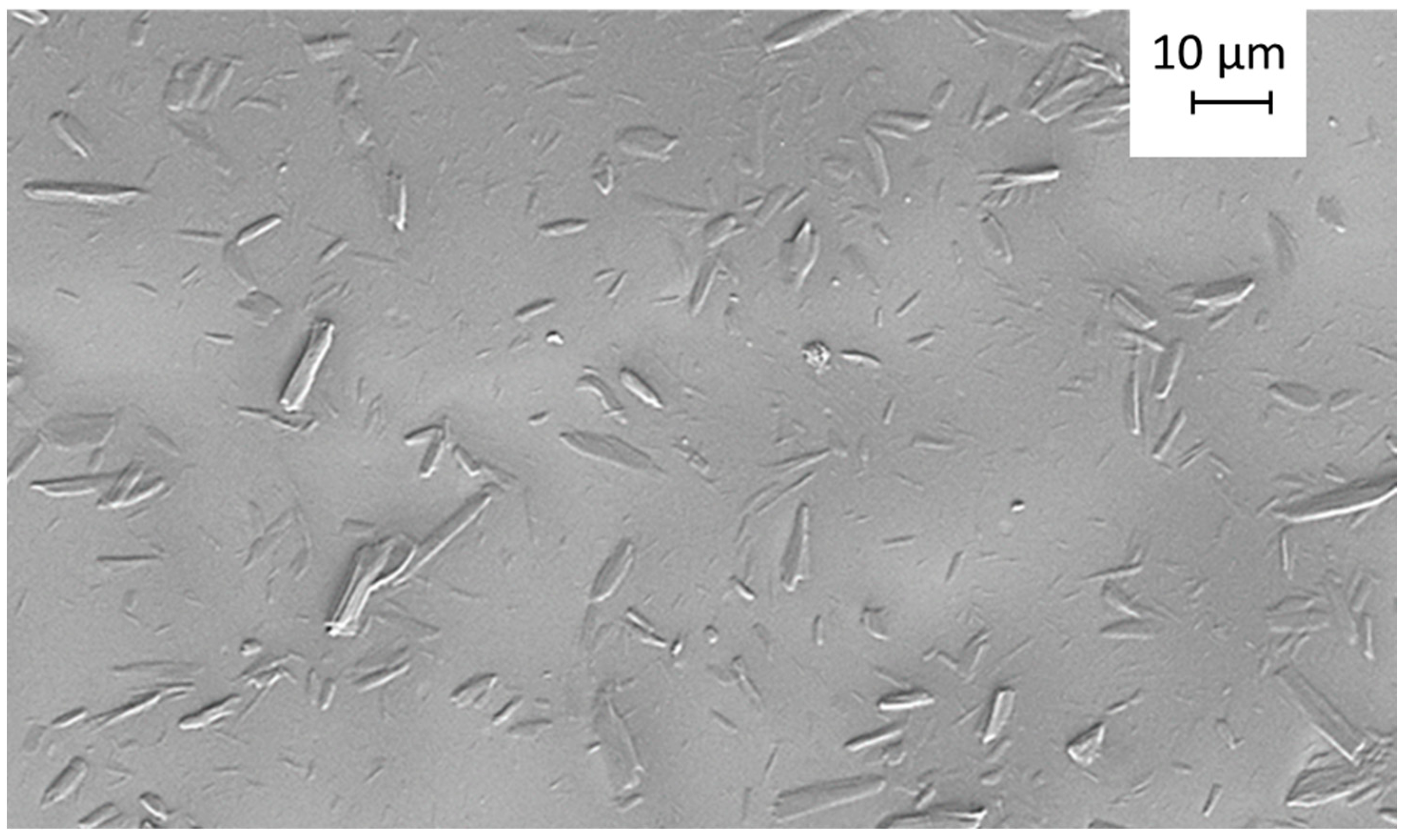
Figure 2.
Change of pH of composite suspensions and their conductivity as a response to change in CNC:UGCC ratio in composite suspensions: (a) pH, (b) conductivity.
Figure 2.
Change of pH of composite suspensions and their conductivity as a response to change in CNC:UGCC ratio in composite suspensions: (a) pH, (b) conductivity.

Figure 3.
Frequency sweep behavior for pure CNC suspensions with different solids contents at different constant strain values, (a) γ = 0.01% and (b) γ = 0.1%, and, correspondingly, transient viscosity (η+) for (c) 2 w/w% and (d) 3 w/w% with three different shear rates, from ultralow to intermediate = 0.01 s−1, 0.1 s−1, and 1 s−1.
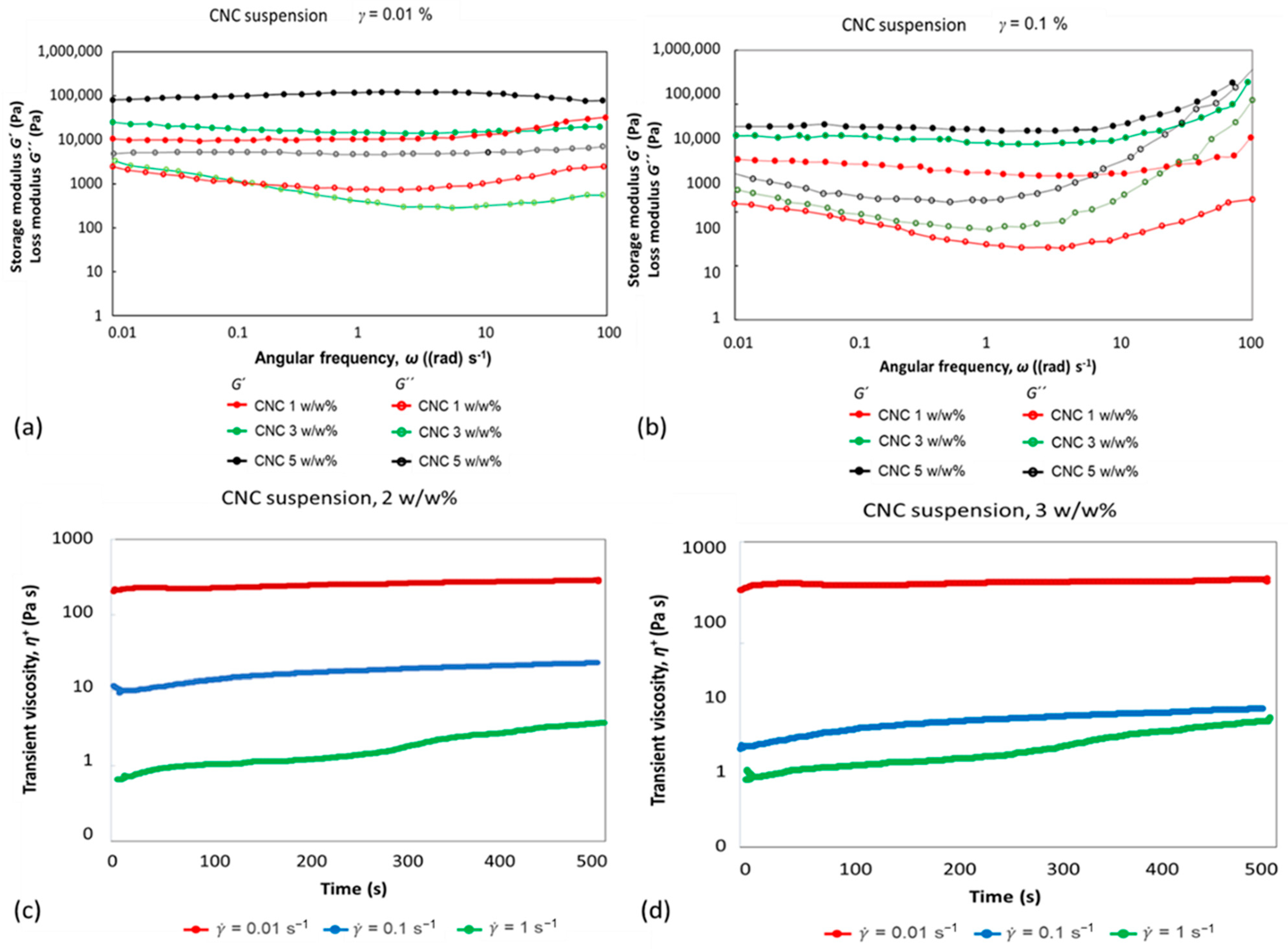
Figure 4.
Influence of aging and autoflocculation of UGCC and CNC on suspension seen through change of storage (G′) and loss (G″) moduli through increased strain range γ = 0.1–1000%, for CNC:UGCC composite suspensions with different volume ratios, (a) CNC:UGCC 70:30, (b) CNC:UGCC 60:40, (c) CNC:UGCC 50:50, (d) CNC:UGCC 40:60, and (e) CNC:UGCC 30:70.
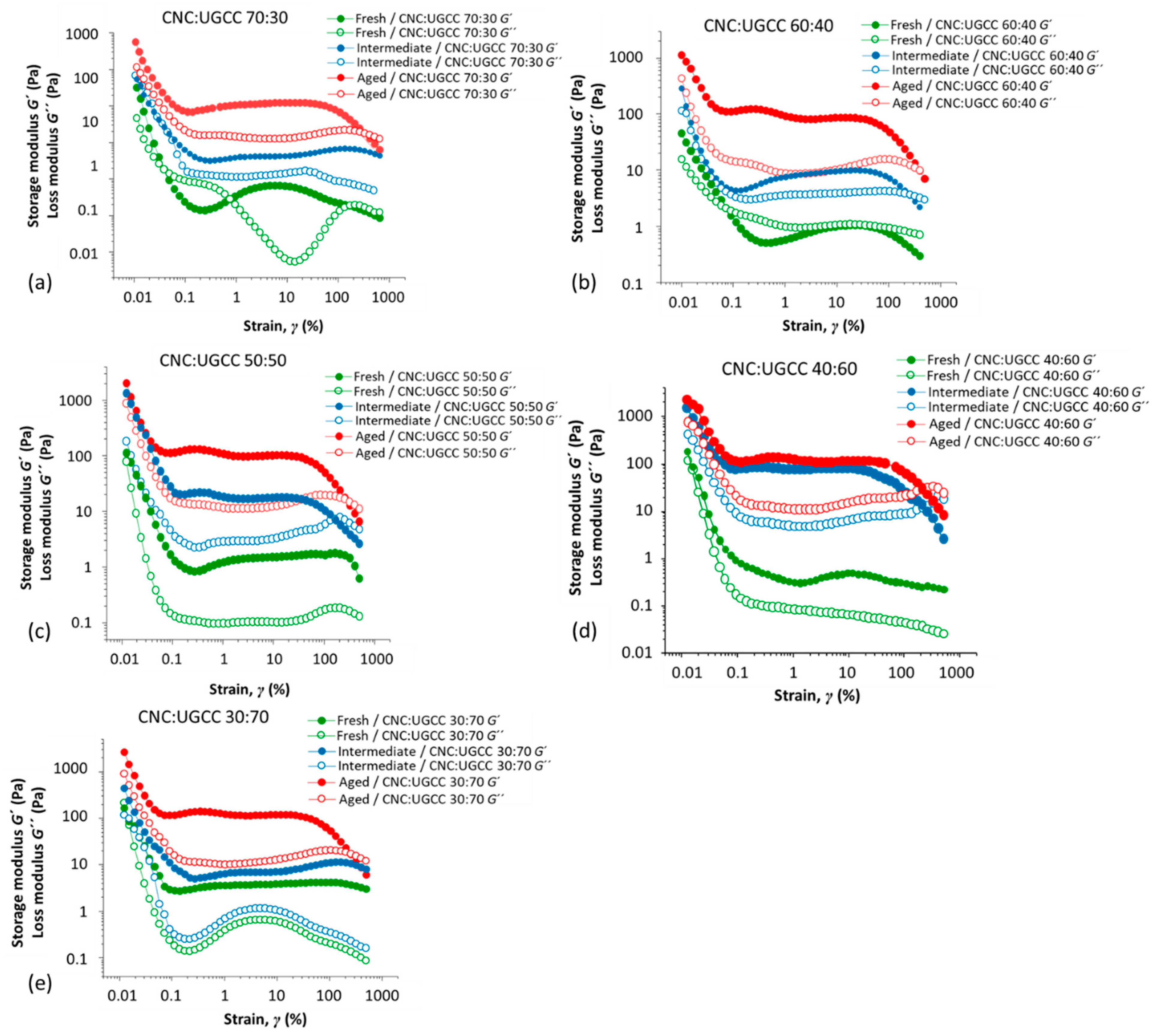
Figure 5.
Influence of aging and autoflocculation of UGCC in CNC suspension seen through change of storage (G′) and loss (G″) moduli as a function of increasing angular frequency through the quasi LVE region, at ω = 0.1–100 (rad) s−1 for CNC:UGCC composite suspensions with different volume ratios: (a) fresh (1 h room temperature), (b) intermediate storage (24 h refrigerated), and (c) aged (72 h refrigerated).
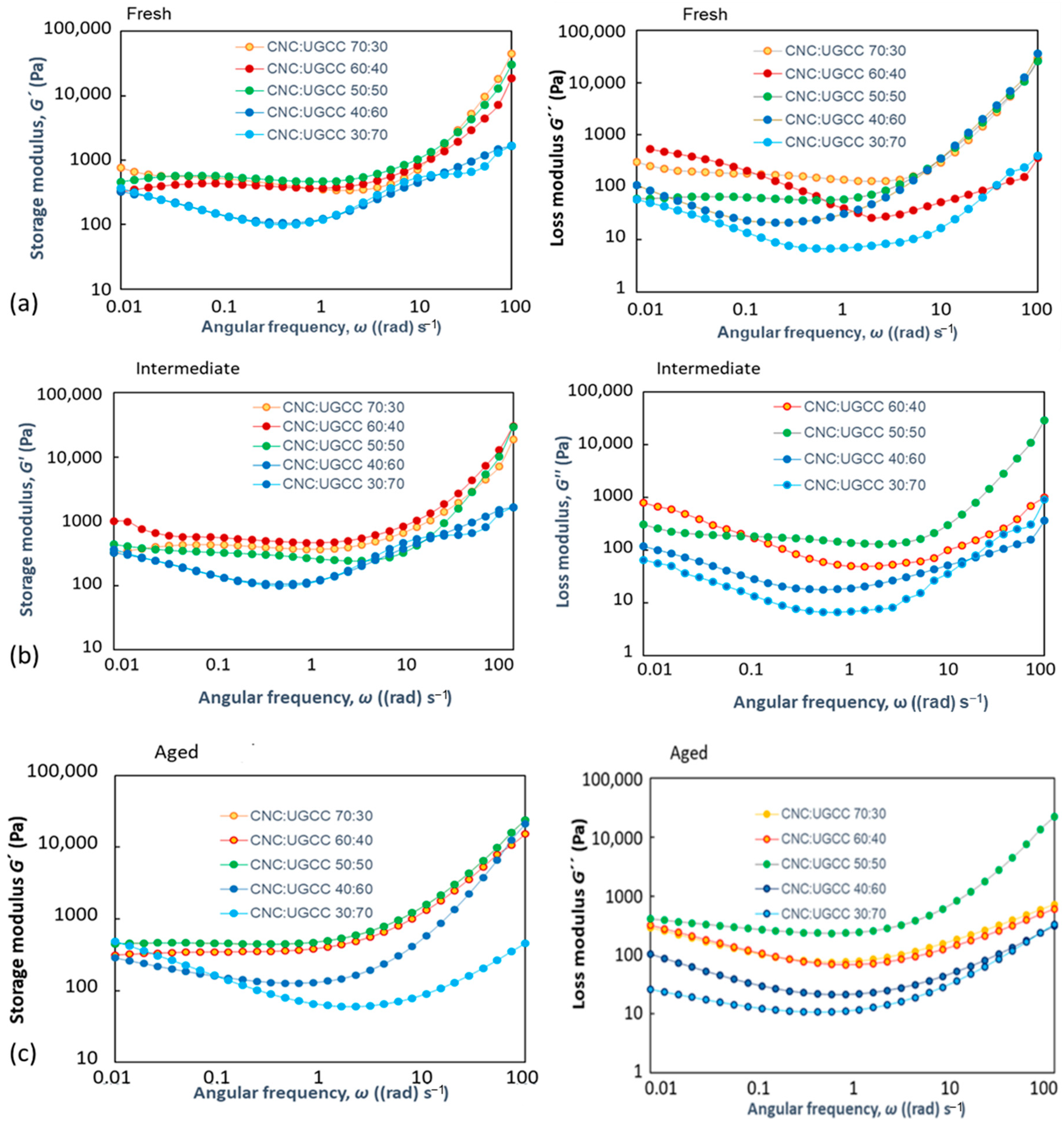
Figure 6.
Influence of aging and autoflocculation of CNC and UGCC in different mixes seen as change of complex viscosity (η*) over the increase of angular frequency through the quasi LVE region, at ω = 0.1–100 rad s−1, for CNC:UGCC composite suspensions with different weight ratios, (a) fresh samples as function of CNC to UGCC weight ratio, and correspondingly, agglomeration-induced dilatant behavior of (η*) presented through reduced values of (η*/η100*) for grouped results averaged over those cases where CNC is the majority component, both are equally present, and UGCC is the majority component, respectively, with the η100* values being for highest angular frequency ω = 100 rad s−1 for (b) fresh samples, (c) intermediate samples, and (d) aged samples.

Figure 7.
Time-dependent behavior of the reduced values of transient viscosity (η+/η0+), where η0+ is the value of η+ at the initiation of measurement, t = 0: (a) fresh, (b) intermediate, and (c) aged samples.
Figure 7.
Time-dependent behavior of the reduced values of transient viscosity (η+/η0+), where η0+ is the value of η+ at the initiation of measurement, t = 0: (a) fresh, (b) intermediate, and (c) aged samples.
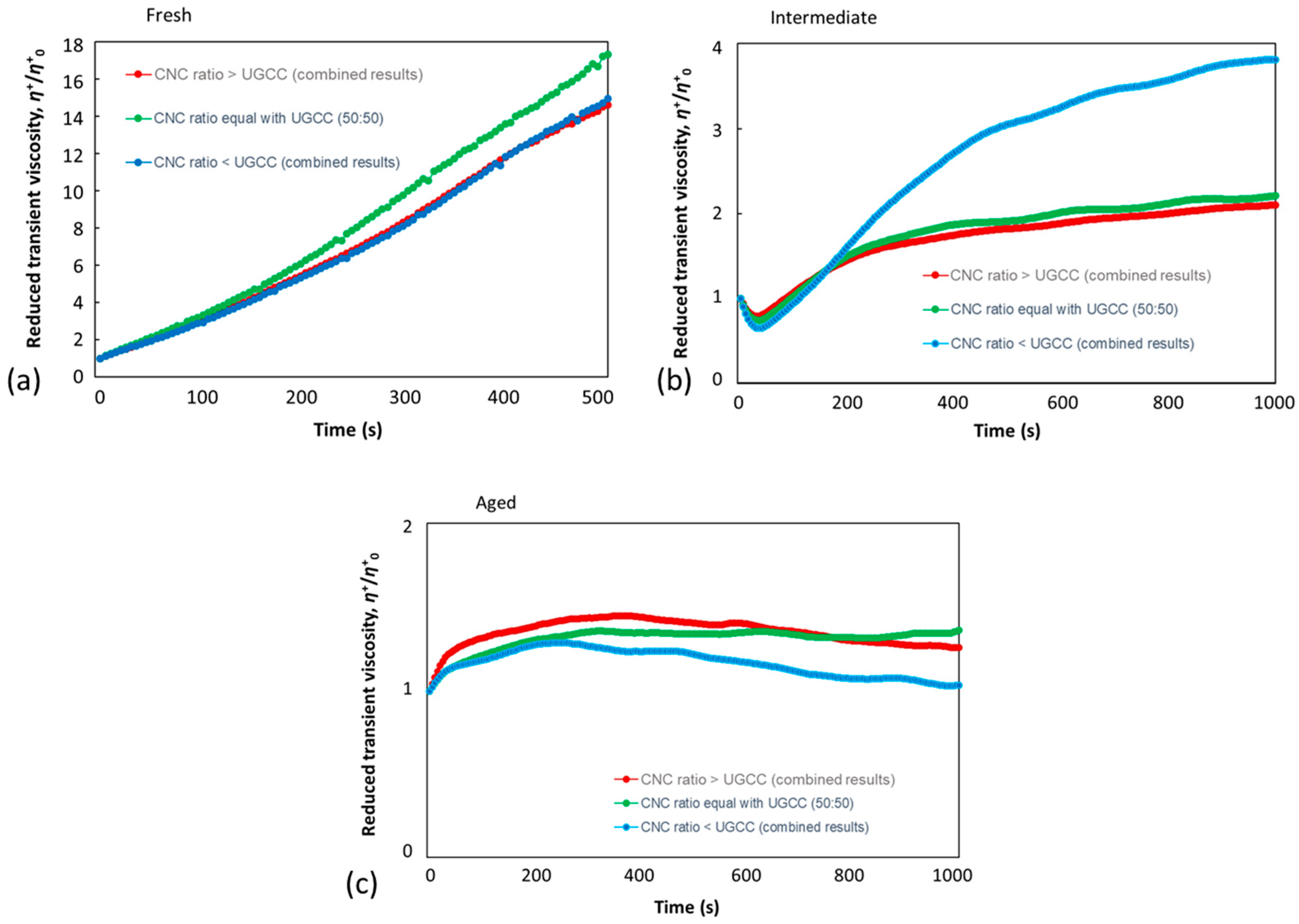
Figure 8.
Flocculation-induced behavior of dynamic viscosity (η) for different mixtures of CNC and UGCC, (a) CNC:UGCC 70:30, (b) CNC:UGCC 60:40, and (c) CNC:UGCC 30:70.
Figure 8.
Flocculation-induced behavior of dynamic viscosity (η) for different mixtures of CNC and UGCC, (a) CNC:UGCC 70:30, (b) CNC:UGCC 60:40, and (c) CNC:UGCC 30:70.
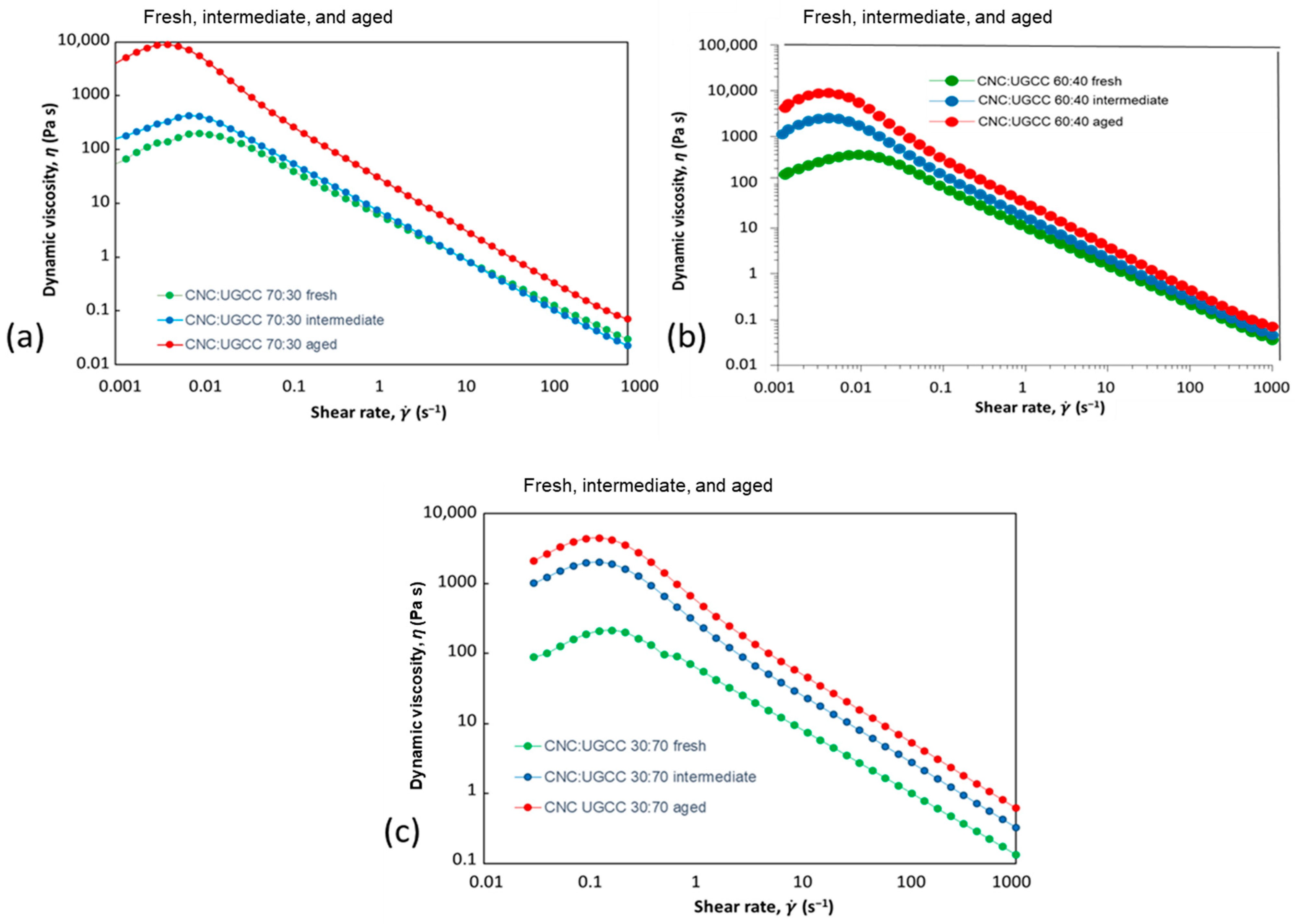
Figure 9.
Transient viscosity (η+) recovery in the 3ITT third interval after exposure to high shear of 1000 s−1 in the second interval. Shear rate for the first and third intervals was equal at 0.01 s−1: (a) CNC:UGCC 70:30, (b) CNC:UGCC 60:40, (c) CNC:UGCC 50:50, (d) CNC:UGCC 40:60, and (e) CNC:UGCC 30:70.
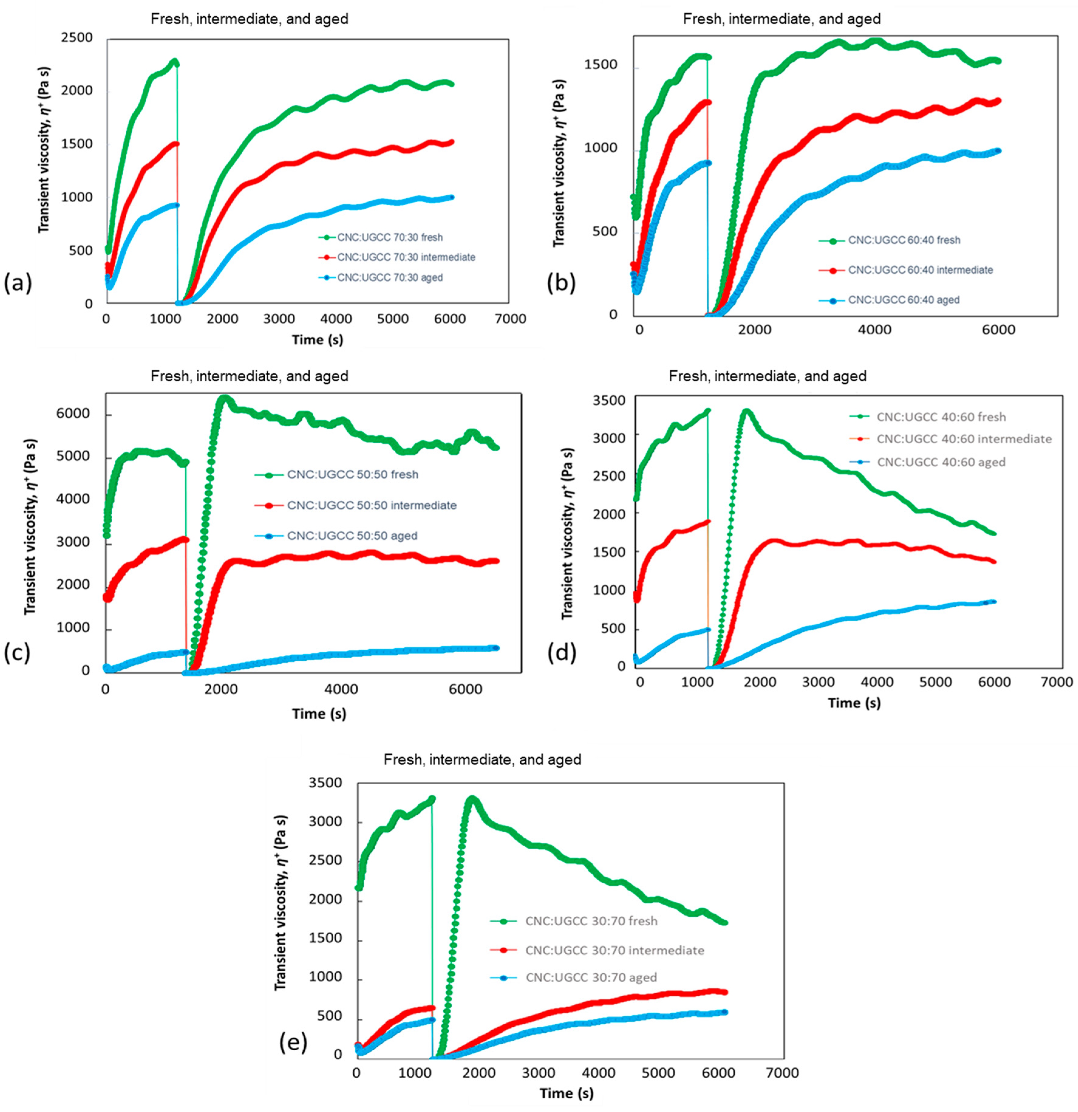
Figure 10.
Schematic representation of the experimental effect of induced gel stress under ultralow shear resulting in suppression of the Brownian motion amplitude and an increase in near neighbor residence time, thus enabling time-dependent heterogeneous adsorption to occur.
Figure 10.
Schematic representation of the experimental effect of induced gel stress under ultralow shear resulting in suppression of the Brownian motion amplitude and an increase in near neighbor residence time, thus enabling time-dependent heterogeneous adsorption to occur.
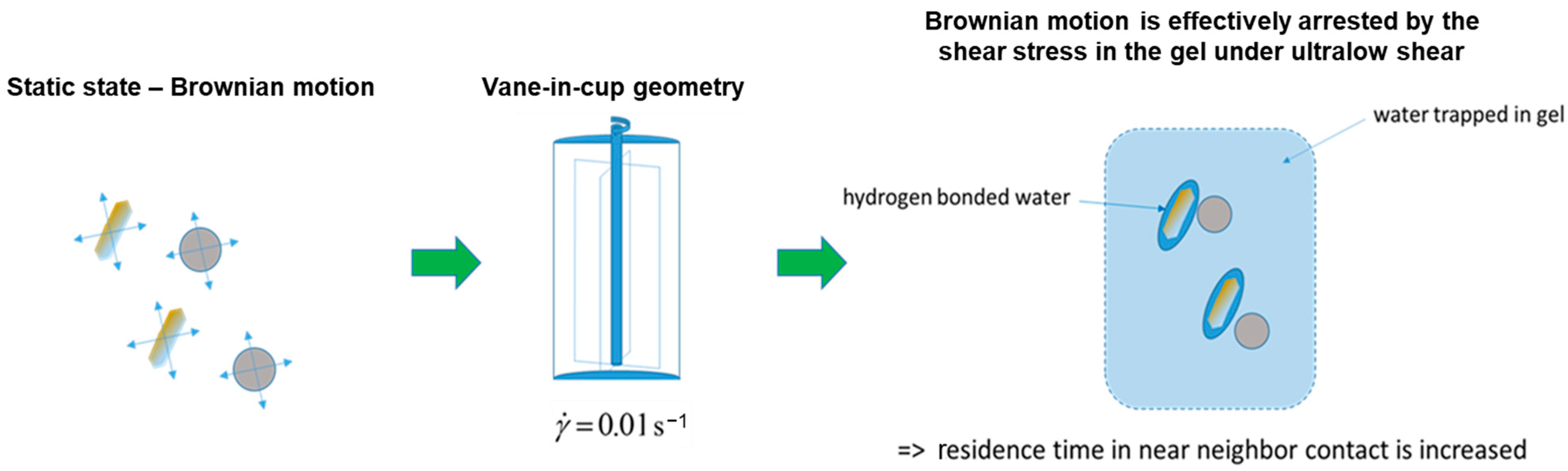
Figure 11.
Capture of structure within the CNC–UGCC suspensions derived under constant ultralow shearing by dipping sheared samples from vane-in-cup geometry into liquid nitrogen and freeze-drying.
Figure 11.
Capture of structure within the CNC–UGCC suspensions derived under constant ultralow shearing by dipping sheared samples from vane-in-cup geometry into liquid nitrogen and freeze-drying.
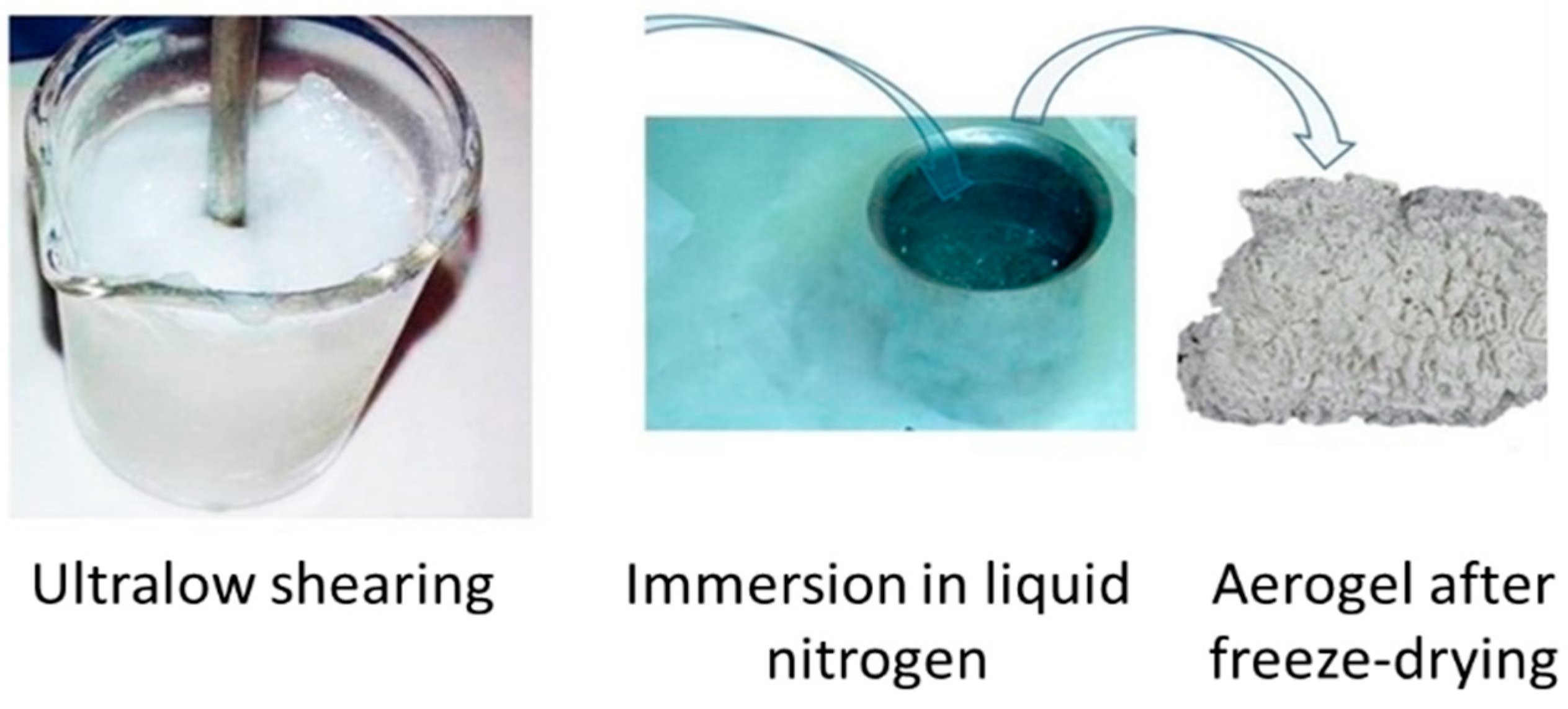
Figure 12.
Optical microscope images of CNC:UGCC 70:30 samples; on left-hand side, are the fresh and aged samples in the stationary state, and on the right, are the fresh and aged samples captured during ultralow shear structuration.
Figure 12.
Optical microscope images of CNC:UGCC 70:30 samples; on left-hand side, are the fresh and aged samples in the stationary state, and on the right, are the fresh and aged samples captured during ultralow shear structuration.
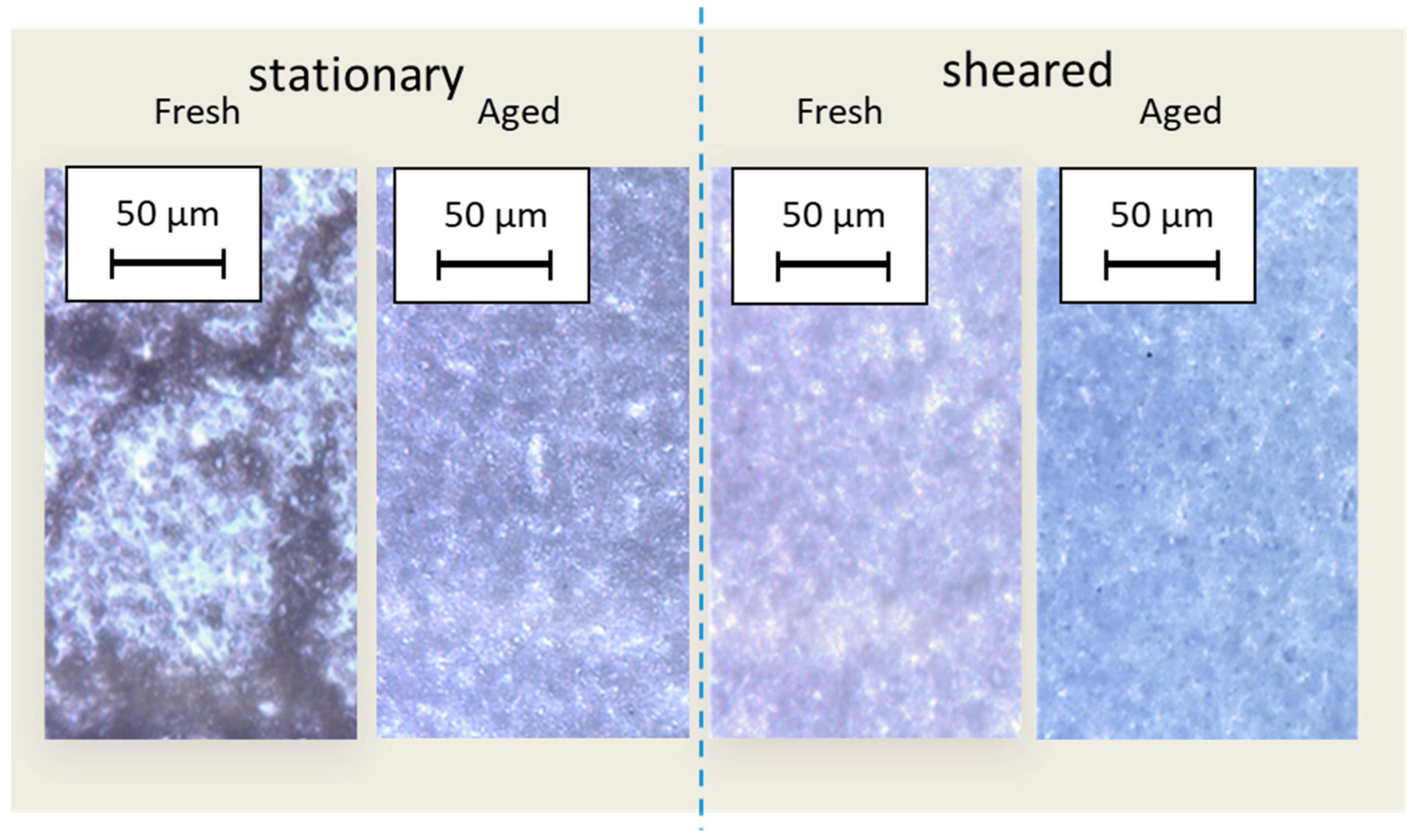
Figure 13.
Optical microscope images of (a) fresh and (b) aged samples in the stationary state and captured during ultralow shear structuration.
Figure 13.
Optical microscope images of (a) fresh and (b) aged samples in the stationary state and captured during ultralow shear structuration.
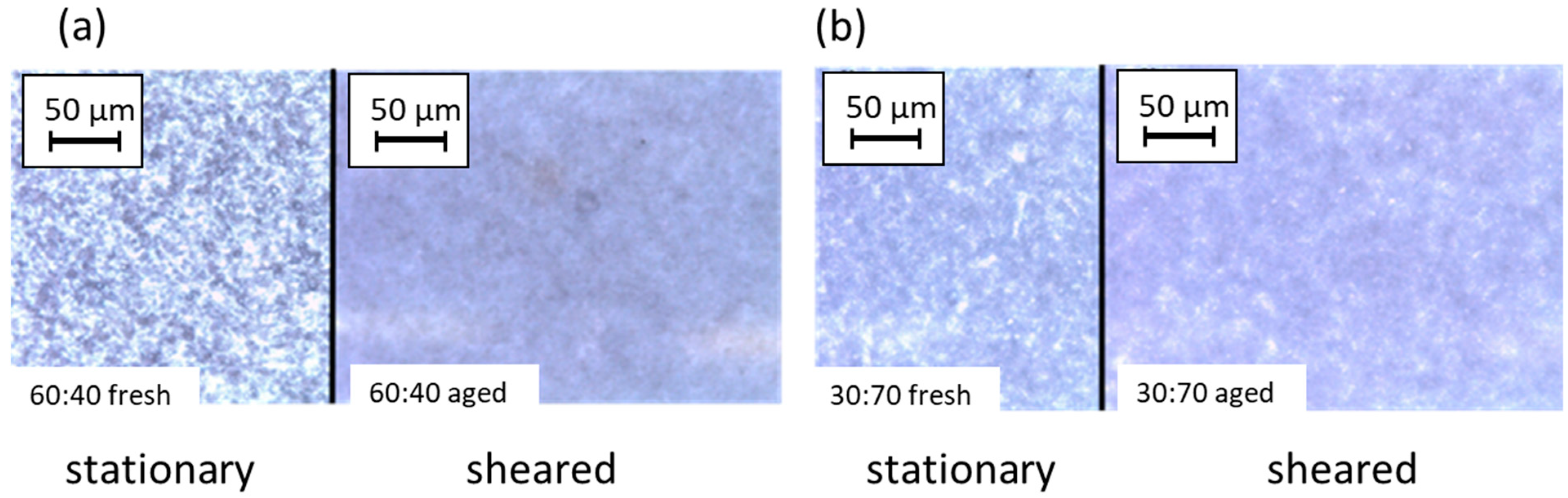
Figure 14.
SEM images from freeze-dried aerogels showing CNC–UGCC layers formed by ultralow shearing, illustrating transitioning from random aggregates to adsorption between UGCC and CNC and subsequent autoflocculation aligned into shear bands. The samples are in the order (a) CNC:UGCC 70:30 unsheared and sheared, (b) CNC:UGCC 60:40 unsheared and sheared, (c) CNC:UGCC 50:50 unsheared and sheared, and (d) CNC:UGCC 30:70 unsheared and sheared.
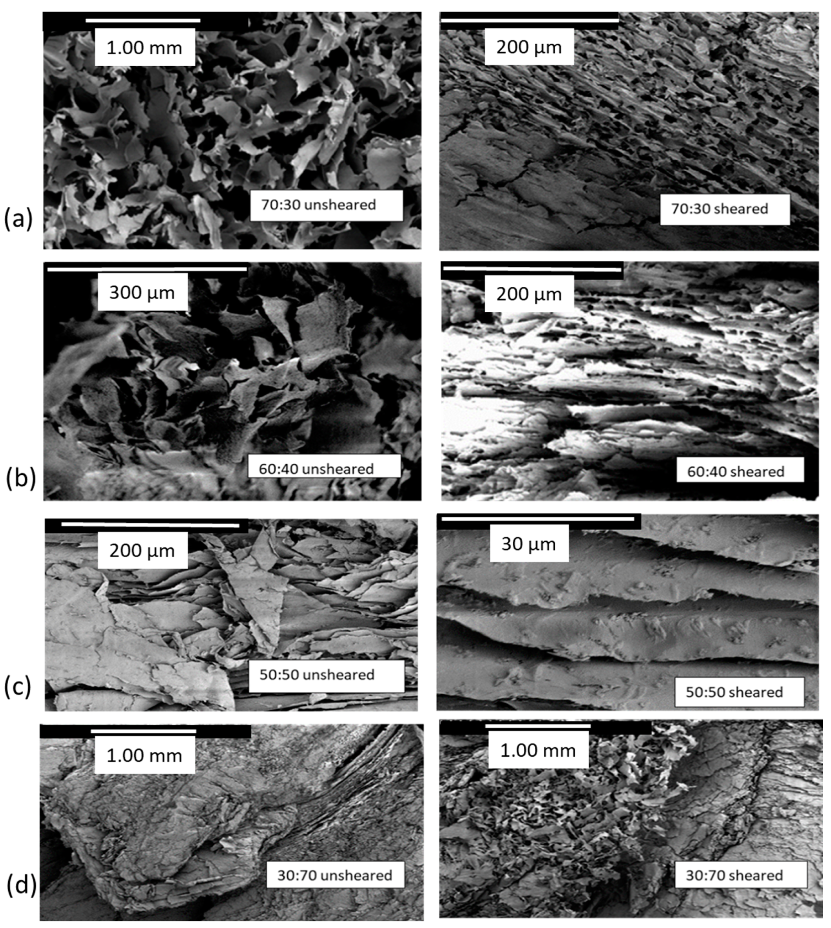
Figure 15.
Digital camera images of the CNC:UGCC 50:50 sample following ultralow shear (0.01 s−1) as a function of time, after 5, 10, and 15 min whilst lifting the vane from the suspension.
Figure 15.
Digital camera images of the CNC:UGCC 50:50 sample following ultralow shear (0.01 s−1) as a function of time, after 5, 10, and 15 min whilst lifting the vane from the suspension.

Figure 16.
Schematic rendering of (a) adsorption of UGCC onto MNFC as suggested by Liu et al., 2017 [23], (b) the contrasting evolution of heterogeneous hierarchical structures during sorption between CNC and UGCC under ultralow shear as a function of increasing UGCC content, leading finally to the autoflocculating superstructure driven by the eventual dominance of calcium carbonate (UGCC) particles on the outer surface, effectively masking the crystalline nanocellulose (CNC), which acts as the glue within the hierarchical structure, and (c) induced dewatering of the final superstructure.


Table 1.
Sample preparation and solids content of each sample type.
| CNC:UGCC Ratio | Total Solids Content Fraction in Suspension (w/w%) | CNC Equivalent Solid Material (g) | CNC Fraction in Suspension (w/w%) | UGCC Equivalent Solid Material (g) | UGCC Fraction in Suspension (w/w%) | Total Equivalent Solid Material (g) |
|---|---|---|---|---|---|---|
| 70:30 | 4.03 | 0.70 | 2.82 | 0.30 | 1.21 | 24.83 |
| 60:40 | 4.55 | 0.60 | 2.73 | 0.40 | 1.82 | 22.00 |
| 50:50 | 5.22 | 0.50 | 2.61 | 0.50 | 2.61 | 19.17 |
| 40:60 | 6.12 | 0.40 | 2.45 | 0.60 | 3.67 | 16.33 |
| 30:70 | 7.41 | 0.30 | 2.22 | 0.70 | 5.19 | 13.50 |
Table 2.
Weight ratios of CNC and respective UGCC pigment to gain the desired total solids weight ratio, while the water ratio in the samples decreases. CNC stock suspension was 3 w/w%. Storage time is also indicated.
Table 2.
Weight ratios of CNC and respective UGCC pigment to gain the desired total solids weight ratio, while the water ratio in the samples decreases. CNC stock suspension was 3 w/w%. Storage time is also indicated.
| Component Fraction CNC:UGCC Based on Solid Weight Ratio | Total Solids Content (w/w%) | Fresh Samples (1 h at Room Temperature) | Intermediate Samples (24 h Refrigerated) | Aged Samples (72 h Refrigerated) |
|---|---|---|---|---|
| 100:0 | 3.00 |  | ||
| 70:30 | 4.03 | |||
| 60:40 | 4.55 | |||
| 50:50 | 5.12 | |||
| 40:60 | 6.12 | |||
| 30:70 | 7.41 | |||
Table 3.
Zeta potential (ζ) and pH of pure CNC and UGCC suspensions prior to mixing.
| Material | ζ (mV) | pH |
|---|---|---|
| CNC | −27.6 | 4.6 |
| UGCC | +0.5 | 10.2 |
Table 4.
Summary of selected comparative values extracted from the rheological measurements for the different CNC:UGCC suspensions in respect to aging and autoflocculation-induced structuration (Figure 4 and Figure 5). Elastic moduli (G′) and loss moduli (G″) are presented at very low angular frequency of ω = 0.01 rad s−1, and after structuration at ω = 80 rad s−1.
| Sample CNC:UGCC | Viscoelastic Moduli at 0.01 (rad) s−1 | Viscoelastic Moduli at 80 (rad) s−1 | ||
|---|---|---|---|---|
| G′ (Pa) | G″ (Pa) | G′ (Pa) | G″ (Pa) | |
| 70:30 fresh | 95.3 | 24.4 | 3127.2 | 356.5 |
| 70:30 intermediate | 113.1 | 32.2 | 1789.5 | 543.3 |
| 70:30 aged | 813.8 | 96.9 | 556.3 | 19.8 |
| 60:40 fresh | 92.1 | 16.9 | 2256.5 | 194.3 |
| 60:40 intermediate | 104.9 | 19.6 | 1398.3 | 287.2 |
| 60:40 aged | 792.4 | 87.6 | 489.9 | 93.6 |
| 50:50 fresh | 82.8 | 11.3 | 1367.3 | 162.5 |
| 50:50 intermediate | 92.5 | 17.3 | 1334.6 | 235.7 |
| 50:50 aged | 728.2 | 65.0 | 421.8 | 83.6 |
| 40:60 fresh | 72.9 | 8.9 | 1268.2 | 92.6 |
| 40:60 intermediate | 84.3 | 9.9 | 1298.4 | 112.9 |
| 40:60 aged | 698.6 | 54.0 | 387.7 | 72.8 |
| 30:70 fresh | 68.5 | 7.8 | 1178.2 | 89.1 |
| 30:70 intermediate | 72.6 | 9.3 | 1267.5 | 92.4 |
| 30:70 aged | 567.4 | 35.5 | 324.8 | 69.7 |
Table 5.
Complex viscosity response for fresh, intermediate, and aged samples of CNC:UGCC suspensions, for low angular frequency ω = 0.1 (rad) s−1, intermediate angular frequency ω = 1 (rad) s−1, and high angular frequency ω = 100 (rad) s−1.
Table 5.
Complex viscosity response for fresh, intermediate, and aged samples of CNC:UGCC suspensions, for low angular frequency ω = 0.1 (rad) s−1, intermediate angular frequency ω = 1 (rad) s−1, and high angular frequency ω = 100 (rad) s−1.
| Sample CNC:UGCC | Complex Viscosity (Pa s) | ||
|---|---|---|---|
| η* at 0.01 (rad) s−1 | η* at 1 (rad) s−1 | η* at 100 (rad) s−1 | |
| 70:30 fresh | 398.25 | 825.47 | 8376.52 |
| 70:30 intermediate | 642.14 | 792.23 | 1428.13 |
| 70:30 aged | 1244.41 | 728.16 | 426.54 |
| 60:40 fresh | 336.34 | 728.32 | 7263.28 |
| 60:40 intermediate | 525.82 | 715.38 | 1361.12 |
| 60:40 aged | 989.72 | 531.52 | 271.49 |
| 50:50 fresh | 290.30 | 688.38 | 6374.82 |
| 50:50 intermediate | 493.06 | 614.52 | 1254.43 |
| 50:50 aged | 917.65 | 509.51 | 383.17 |
| 40:60 fresh | 81.46 | 662.53 | 2621.36 |
| 40:60 intermediate | 398.56 | 595.26 | 1108.74 |
| 40:60 aged | 884.45 | 594.12 | 465.31 |
| 30:70 fresh | 79.56 | 749.98 | 2372.93 |
| 30:70 intermediate | 382.78 | 574.74 | 957.26 |
| 30:70 aged | 921.35 | 467.24 | 384.23 |
Table 6.
Transient viscosity at the initiation of the measurement (t = 0) and at point t = 1000 s.
| Sample CNF:UGCC | Transient Viscosity (Pa s) = 0.01 s−1 | |
|---|---|---|
| η+t= 0 (η0+) | η+t= 1 000 | |
| 70:30 fresh | 159.35 | 3549.98 |
| 70:30 intermediate | 1295.78 | 2281.74 |
| 70:30 aged | 4121.35 | 5250.23 |
| 60:40 fresh | 236.34 | 978.23 |
| 60:40 intermediate | 1745.62 | 3876.34 |
| 60:40 aged | 3317.42 | 5181.82 |
| 50:50 fresh | 98.30 | 1288.81 |
| 50:50 intermediate | 733.02 | 1481.56 |
| 50:50 aged | 3676.65 | 3361.84 |
| 40:60 fresh | 65.56 | 1160.57 |
| 40:60 intermediate | 294.16 | 1275.23 |
| 40:60 aged | 3502.23 | 3129.21 |
| 30:70 fresh | 46.65 | 1095.23 |
| 30:70 intermediate | 78.32 | 235.57 |
| 30:70 aged | 13,292.17 | 117.84 |
Table 7.
Dynamic viscosity η as a function of shear rate, , fitted to the power law model with parameters k and n, from reduced viscosity curves, shows shear rate response and break up of flocculation in respect to aging of suspensions with different ratios of CNC to UGCC.
Table 7.
Dynamic viscosity η as a function of shear rate, , fitted to the power law model with parameters k and n, from reduced viscosity curves, shows shear rate response and break up of flocculation in respect to aging of suspensions with different ratios of CNC to UGCC.
| Sample CNC:UGCC | (at Effective Zero Shear) | k | n | ||
|---|---|---|---|---|---|
| (s−1) | (Pa s) | (Pa s) | (Pa sn) | ||
| 70:30 fresh | 0.065 | 718.5 | 687.6 | 78 | 0.92 |
| 70:30 intermediate | 0.078 | 840.6 | 722.4 | 144 | 0.87 |
| 70:30 aged | 0.163 | 4423.7 | 2871.5 | 287 | 0.85 |
| 60:40 fresh | 0.052 | 687.6 | 645.5 | 71 | 0.87 |
| 60:40 intermediate | 0.064 | 747.2 | 686.4 | 88 | 0.85 |
| 60:40 aged | 0.125 | 3523.3 | 2165.6 | 210 | 0.84 |
| 50:50 fresh | 0.004 | 615.3 | 560.5 | 68 | 0.82 |
| 50:50 intermediate | 0.008 | 633.1 | 578.5 | 85 | 0.80 |
| 50:50 aged | 0.010 | 2911.8 | 1786.7 | 188 | 0.78 |
| 40:60 fresh | 0.002 | 556.6 | 438.8 | 62 | 0.76 |
| 40:60 intermediate | 0.006 | 598.5 | 489.7 | 81 | 0.75 |
| 40:60 aged | 0.008 | 613.5 | 46.3 | 178 | 0.73 |
| 30:70 fresh | 0.002 | 425.0 | 378.5 | 58 | 0.72 |
| 30:70 intermediate | 0.003 | 515.2 | 478.2 | 72 | 0.71 |
| 30:70 aged | 0.009 | 689.0 | 589.3 | 145 | 0.67 |
Table 8.
Transient viscosity (η+) recovery and structure build-up during 3ITT measurements.
| Sample CNC:UGCC | Third 3ITT Interval |
|---|---|
| Recovery Time for Transient Viscosity (s) | |
| 30:70 fresh | 2489 |
| 30:70 intermediate | 1578 |
| 30:70 aged | 1439 |
| 40:60 fresh | 2649 |
| 40:60 intermediate | 1388 |
| 40:60 aged | 1321 |
| 50:50 fresh | 4885 |
| 50:50 intermediate | 3457 |
| 50:50 aged | 2954 |
| 60:40 fresh | 2678 |
| 60:40 intermediate | 2768 |
| 60:40 aged | 2013 |
| 70:30 fresh | 2666 |
| 70:30 intermediate | 3100 |
| 70:30 aged | 3350 |
Disclaimer/Publisher’s Note: The statements, opinions and data contained in all publications are solely those of the individual author(s) and contributor(s) and not of MDPI and/or the editor(s). MDPI and/or the editor(s) disclaim responsibility for any injury to people or property resulting from any ideas, methods, instructions or products referred to in the content. |
© 2023 by the authors. Licensee MDPI, Basel, Switzerland. This article is an open access article distributed under the terms and conditions of the Creative Commons Attribution (CC BY) license (https://creativecommons.org/licenses/by/4.0/).
Share and Cite
MDPI and ACS Style
Liukko, S.; Dimic-Misic, K.; Ge, Y.; Gane, P. Heterogeneous Hierarchical Self-Assembly Forming Crystalline Nanocellulose–CaCO3 Hybrid Nanoparticle Biocomposites. J. Compos. Sci. 2023, 7, 333. https://doi.org/10.3390/jcs7080333
AMA Style
Liukko S, Dimic-Misic K, Ge Y, Gane P. Heterogeneous Hierarchical Self-Assembly Forming Crystalline Nanocellulose–CaCO3 Hybrid Nanoparticle Biocomposites. Journal of Composites Science. 2023; 7(8):333. https://doi.org/10.3390/jcs7080333
Chicago/Turabian StyleLiukko, Sirje, Katarina Dimic-Misic, Yanling Ge, and Patrick Gane. 2023. "Heterogeneous Hierarchical Self-Assembly Forming Crystalline Nanocellulose–CaCO3 Hybrid Nanoparticle Biocomposites" Journal of Composites Science 7, no. 8: 333. https://doi.org/10.3390/jcs7080333