Article

Diagonal Compression Tests on Unfired and Fired Masonry Wallettes Retrofitted with Textile-Reinforced Alkali-Activated Mortar

by
Andres Arce
,
Panagiotis Kapsalis
*,
Catherine G. Papanicolaou
and
Thanasis C. Triantafillou
Department of Civil Engineering, University of Patras, 26504 Patras, Greece
*
Author to whom correspondence should be addressed.
J. Compos. Sci. 2024, 8(1), 14; https://doi.org/10.3390/jcs8010014
Submission received: 21 November 2023 / Revised: 21 December 2023 / Accepted: 27 December 2023 / Published: 29 December 2023
(This article belongs to the Special Issue Feature Papers in Journal of Composites Science in 2023)

Abstract

:
This paper discusses the integration of an alkali-activated mortar (AAM), based on industrial waste, into a novel composite material fit for structural upgrading purposes and rendered with high temperature endurance and a low CO2 footprint. The AAM combined with carbon fiber textiles form a new generation of sustainable inorganic matrix composites—that of textile-reinforced alkali-activated mortars (TRAAM). A test program was designed to assess the effectiveness of carbon TRAAM overlays in increasing the shear capacity of masonry wall specimens comprising solid clay bricks bonded with lime-based mortar and furnished with TRAAM jackets on both sides. The initial and the residual capacity of the reinforced walls were evaluated, the latter by performing diagonal compression tests after exposure to 300 °C and 550 °C. It was shown that TRAAM jacketing can increase the shear capacity of unfired masonry walls by 260% and 335% when a single or a double layer of textile is used, respectively. Rapid heating to temperatures up to 550 °C, one-hour-long steady-state heating, and natural cooling bore no visible thermal cracks on the specimens and had little effect on their residual capacity. Based on these results, the prospect of using TRAAM for retrofitting applications for fire-resilient structures seems very auspicious.

1. Introduction

The European construction sector is showing an increased need for the retrofitting, maintenance and repair of its existing aging infrastructure compared to the growth of new construction in Latin America and Asia [1]. The application of textile-reinforced mortars (TRM) is a retrofitting/repair technique that has gained popularity in the last decades. TRM are produced by embedding (predominantly) nonmetallic fibers of high tensile strength into inorganic matrices such as cementitious mortar or—more recently—mortars based on alkali-activated materials (AAM). The fibers used are woven into textiles with spacings between rovings (or bundles) that usually vary from 5 to 35 mm. The spacing between the fiber bundles allows the mortar to penetrate the textiles and generate a mechanical interlock between the matrix and the reinforcement [2,3]. The application of TRM has proven to be an effective solution for masonry retrofitting by numerous studies [4,5,6,7], some of which have highlighted the effectiveness of this technique compared to its predecessor repair solution, fiber-reinforced polymers (FRP). Apart from their effectiveness in increasing the load-bearing and deformation capacity of the masonry elements, TRM also exhibit a better compatibility than FRP with masonry as a substrate, whereas the application of TRM on uneven surfaces is easier than the application of FRP [8,9]. Specifically for historical masonry elements (which lie in the scope of this study), the irreversibility of the application of FRP is another obstacle that may be partially overcome with the use of TRM [10]. In addition, TRM have the advantage of allowing moisture to escape due to their high porosity when compared to FRP overlays. This particular characteristic is of special importance when repairing historical masonry, where moisture can rise from the foundations and become trapped in the reinforced masonry, resulting in further damage to the existing materials. Furthermore, TRM reinforcement has the advantage of improving the strength of existing structural elements without influencing the mass distribution and rigidity of the structure [11]. Finally, TRM have higher stability against heat due to the use of an inorganic matrix instead of epoxy (the glass transition temperature for epoxies is around 65–120 °C [12]). In fact, TRM have shown appreciable resistance to heat and fire, retaining a considerable fraction of their initial strength and tensile modulus after exposure to temperatures higher than 400 °C [13,14,15,16,17,18]. The heating/cooling and mechanical testing conditions seem to play a major role in the results, while the utilization of heat-resistant carbon fibers and the absence of polymer textile coatings promotes the strength and stiffness retaining of the TRM elements [19].
It has been well-documented in the literature that masonry panels also exhibit good behavior at high temperatures [20,21,22,23]. This is mainly because of the heat resistance of the commonly used fired clay bricks and because of the large mass of the load-bearing masonry elements that delay the temperature increase throughout the whole element. Nevertheless, according to Eurocode 2 [24], masonry elements of clay units with general purpose mortar have no residual strength at temperatures above 600 °C. In addition, evidence from references [25,26,27,28] show that the bond between the masonry substrate and the TRM overlay is strongly affected by elevated temperatures, and quickly deteriorates (an approximately 50% load reduction after exposure to nominal air temperatures of 300–400 °C). However, there are extremely few studies on the fire performance of TRM-strengthened masonry elements (e.g., [29,30]). Thus, despite the relatively good performance of masonry and TRM at high temperatures, further research is required to determine the fire performance of a strengthening scheme.
Apart from the thermal and mechanical performance of retrofitted masonry structures, the environmental footprint of the strengthening techniques is another aspect of major importance. Studies on AAM technology have demonstrated the potential to produce binders with remarkably low CO2 emissions when compared to traditional ordinary Portland cement (OPC). The exact reduction depends on the aluminosilicate source (precursor) and alkali metals used to create the binder and their proportions. Duxson et al. [31] reported a reduction of 80% through the alkali activation of a fly ash (FA) and metakaolin (MK) blend. A study led by the first author [32] reported on the production of an AAM mortar based on the activation of ferronickel slag (FNS) for which a CO2 reduction of 70% (compared to a counterpart OPC-based mortar) was achieved. The development of novel techniques, such as TRM based on AAM, is necessary for the construction sector to reduce the dependency on OPC and the sector’s CO2 emissions; the latter range from 5 to 8% [33] of the total global emissions due to the 1.6 billion tons of cement consumed every year [34]. While AAM-based construction solutions have the potential to help improve the sustainability of the construction industry, it is the lack of regulations that has discouraged stakeholders from promoting this technique [35]. This study aims to fill some of the research gaps that need to be addressed in order to develop these regulations, particularly the high temperature behavior of AAM applied as a strengthening material.
Ferronickel slag (FNS) was selected as the precursor for AAM production due to its high availability in Greece (where this study was performed) and its proven efficiency in high temperature applications [36]. Every year, approximately 2 million tons of FNS are produced in Greece (reported in 2022 [37]), and only 20–30% of it is reutilized, with the rest being disposed in landfills or under the sea, with an incurred relocation cost of EUR 650,000/year (in 2007 prices) [38]. To maximize the utilization rate of FNS and reduce the dependency on natural resources, FNS was used as sand replacement (fraction 0–2 mm). Parallel to the global warming problem, natural resource scarcity is yet another pressing issue. The global rate of sand consumption has tripled in the last two decades [39]. This rate has already exceeded the natural recovery rate of sand through the weathering of rocks by wind and water. The reutilization of slag as a sand replacement not only solves the problem of relocating of this by-product, but simultaneously provides an answer to the growing sand depletion problem. A possible obstacle to the utilization of FNS as sand is the risk of alkali–silica reactions. However, while this might be a problem in OPC-based mortars, in AAM, the reactive alkali in the sand is activated by the alkaline solution resulting in a significant reduction in the alkali–silica reaction potential; instead, an improvement in mechanical properties has been observed when using FNS sand in AAM [40].
Russo et al. [20] reported on diagonal compression tests of unreinforced masonry specimens (with solid clay bricks bonded by a cement-based mortar, in a ‘gothic bond’ pattern) exposed to high temperatures (heating rate = 19 °C/min—steady-state duration: 1 h); they showed that the masonry shear capacity remains unaffected after heating at a relatively low temperature (300 °C), whereas important reductions were recorded after heating at 600 °C (of approximately 35%). To the best of the authors’ knowledge, there is only one study available in the literature regarding the effect of temperature on the residual shear capacity of masonry walls reinforced with TRM jackets [30]. In this study, the masonry panels (manufactured with solid clay bricks and lime-based mortar, simulating historical masonry elements), were strengthened with textile-reinforced lime-based mortar (a common practice for historical masonry buildings for compatibility reasons). According to the researchers, the residual capacity of TRM-strengthened masonry showed significant reductions, in the order of 35% for carbon TRM and 50% for glass TRM, after exposure to 600 °C, with respect to the unfired specimens. In addition, both cases (carbon and glass TRM-strengthened and fired walls) suffered excessive reduction in the ductility that the TRM jackets had provided. Specifically for the carbon TRM, as reported by the researchers, the post-peak phase was short, the carbon fibers were pulled out of the matrix and the lime-based TRM jacket was detached from the masonry substrate. The loss of the bond between the TRM jackets and the masonry substrate due to high temperature exposure seems to be a critical issue as reported in studies focusing on the effect of high temperature on the TRM-to-masonry bond. For example, in the study of Iorfida et al. [28], delamination between the TRM (cement-based matrix, carbon fiber textile) and masonry was observed after exposure to 300 °C and 500 °C. It is also noteworthy that, in the study of Askouni et al. [27], it has been reported that the alkali-activated textile-reinforced mortars showed a better TRM-to-masonry bond endurance against increased temperatures compared to the cement-based counterparts.
In summary of the above, knowledge on the performance of TRM-strengthened historical masonry panels after exposure to high temperatures is very scarce and the heat-induced bond deterioration between masonry and cement- or lime-based TRM is significant. Ferronickel slag-based alkali-activated mortars have been shown to exhibit high endurance against increased temperatures and can be thought of as viable alternatives to conventional TRM matrices also aligning with the ever-growing need to use more eco-friendly materials. Nevertheless, the experimental validation of such a course of action remains to be addressed. Therefore, in this paper, the authors explore the application of an alkali-activated textile-reinforced mortar (TRAAM) system to increase the diagonal shear capacity of masonry wallettes under both ambient and post-fire conditions. Replicates of historical solid clay bricks were used to build eighteen single-wythe masonry wallettes measuring 700 × 700 × 100 mm. Six wallettes were left unreinforced to serve as control specimens. The rest of the wallettes were then reinforced on both sides with either one or two layers of carbon fiber textile. Prior to testing, the specimens were either stored in ambient temperature conditions (20 °C) or they were exposed to high temperatures (300 °C and 550 °C—nine combinations and, in total, two wallettes per case). Diagonal compression tests were performed to assess the effect of TRAAM two-sided jacketing on both fired and unfired specimens. The response surface methodology was used to develop models for peak shear stress, shear modulus and ductility as a function of the area of textile reinforcement and temperature of exposure.
At the time this research was performed there were no previous results showcasing the applicability of alkali activation in the production of textile-reinforced mortar solutions for high temperature applications. The present research aims to fill this knowledge gap and, furthermore, through demonstrating the effectiveness of the proposed technique, to encourage further research into the potential benefits of low calcium alkali-activated materials in civil engineering applications where durability under high temperatures is a key parameter.

2. Materials and Methods

2.1. Raw Materials

The mortar was prepared through the alkali activation of ferronickel slag. The slag was provided by the General Mining and Metallurgical Company SA in Greece, “LARCO”, Larissa, Greece, and was used both as an aluminosilicate source for the alkali activation process and as a fine aggregate after sieving and retaining the portion below 2 mm in size. The ground ferronickel slag (GFNS) was grounded in a ball mill to a d50 of 8.36 μm. Silica fume (SF, d50 = 12.87 μm) was also added. The diameters of the particles were measured through laser diffraction using a Malvern Mastersizer 2000 (Malvern Panalytical Ltd, UK). Potassium silicate (KS) of modulus 1.6 and potassium hydroxide (KOH, 90% purity) were used as chemical activators. KS was purchased as a proprietary solution which is composed of 45% KS and 55% water. The chemical composition of both GFNS and SF is reported in Table 1. The results were obtained through X-ray fluorescence (XRF).
The masonry wallettes were built using solid clay bricks and lime mortar in a running bond pattern. The solid bricks of dimensions 200 × 100 × 50 mm had a compressive strength of 20.2 MPa, and a density of 1981 kg/m3, as provided by the manufacturer. The mortar for wall construction was prepared using natural hydraulic lime NHL 3.5, silica sand (0–2 mm) and faucet water at a ratio of 1:3.5:1.5 (by volume), respectively, mimicking the mortar found in historical masonry walls with lime joint mortar. The 90-day compressive strength of the masonry mortar was found to be equal to 1.5 MPa based on nine 160 × 40 × 40 mm prisms sampled during wallettes’ construction; its flexural strength was equal to 0.3 MPa.
An uncoated carbon fiber textile was used as reinforcement. The textile had the same quantity of fibers in both orthogonal directions and an areal weight of 170 g/m2. The center line distance between the fiber bundles was 10 mm. The nominal thickness of the textile was taken as reported by the manufacturer equal to 0.048 mm (per yarn direction). Previous characterization tests executed by Kapsalis et al. [13] (individual results not included in this study) allowed for measuring the textile average peak stress, strain at peak stress and modulus of elasticity, which corresponded to 2231 MPa, 0.0105 and 212.5 GPa, respectively. The alkali-activated mortar recipe was the product of a mortar mix optimization effort based on the experiment and mixture designs [41]. The original recipe was modified to increase the workability by increasing the activator solution content (sum of water, KS and KOH). The ingredient proportions for the 1 m3 of mortar used in this study corresponded to 815 kg of GFNS, 59.7 kg of SF, 1192 kg of ferronickel sand, 32.3 kg of KOH, 76.9 kg of KS and 289 kg of faucet water. Eighteen prisms (160 × 40 × 40 mm) were cast. The 90-day compressive and flexural strengths of the alkali-activated mortar prisms were assessed following EN 1015-11 [42] and they were, respectively, found to be equal to 77.9 MPa and 9.8 MPa.

2.2. Specimen Preparation

All masonry wallettes measured 700 × 700 × 100 mm and were built by a professional mason. The solid bricks were submerged in water one day prior to the specimens’ construction and they were left to dry for a few minutes before being used to promote saturated/surface-dry conditions. The joint thickness was kept at 10 mm. After the wallettes were completed, their surfaces were cleaned of dust with a wet towel and covered with wet burlap to keep them moist for two weeks. Finally, they were left to mature for 90 days before the application of the TRAAM overlays.
One day before TRAAM application, the wallettes were covered with burlap soaked in water until 30 min prior to mortar application to dampen the application areas. For the specimens strengthened with one layer of reinforcement, the first layer of mortar was applied at a thickness of approximately 5 mm. Then, the textile was placed onto and pressed into the fresh mortar using flat spatulas and it was finally covered by the external mortar layer (approximately 4 mm thick). A similar jacketing scheme was followed for the specimens receiving double-layered jackets with the only difference being the addition of a second layer of textile covered by a third layer of 4 mm thick mortar. The reinforced wallettes were cured under ambient conditions (temperature: 5–20 °C and relative humidity: 60–75%) for 30 days using thin plastic foil to prevent moisture loss. The wallettes were left to dry for an additional time span of 60 days before heat exposure.
The chemical activator was prepared one day in advance. The dry ingredients were added in the following order: GFNS, SF, FNS sand and alkaline activator solution. The mortar was first mixed slowly for 15 s to let the dry part absorb the solution and avoid splashing. Once the solution was absorbed, the mortar was mixed for 2 min using an electric hand mixer. The pot was then tilted to gain access to the bottom of the pot and remove any material stuck in the borders. This procedure took approximately 2 min. Finally, the mortar was mixed again for 3 min.
The nomenclature of the specimens (see also Table 2) followed the rule, XX_TYYY_Z, where XX takes the designation “Un” for unreinforced (control) specimens, “1L” for wallettes reinforced with one layer of textile on each side and “2L” for wallettes reinforced with two layers of textile on each side; TYYY indicates the exposure temperature, taking the designation “T20” for specimens kept in ambient conditions until testing, and “T300” and “T550” for specimens exposed to 300 °C and 550 °C, respectively, before testing; Z takes the designations “a” and “b” to indicate the two separate replicate specimens for each test group. For instance, the specimen named as 1L_T300_b is the second wallette strengthened with one layer of textile on each side, which was exposed to a temperature of 300 °C prior to mechanical testing. Specimen groups Un_T300 and Un_T550 are missing from Table 2 since they did not survive the transportation from the furnace to the test rig or the handling for test-ready positioning.

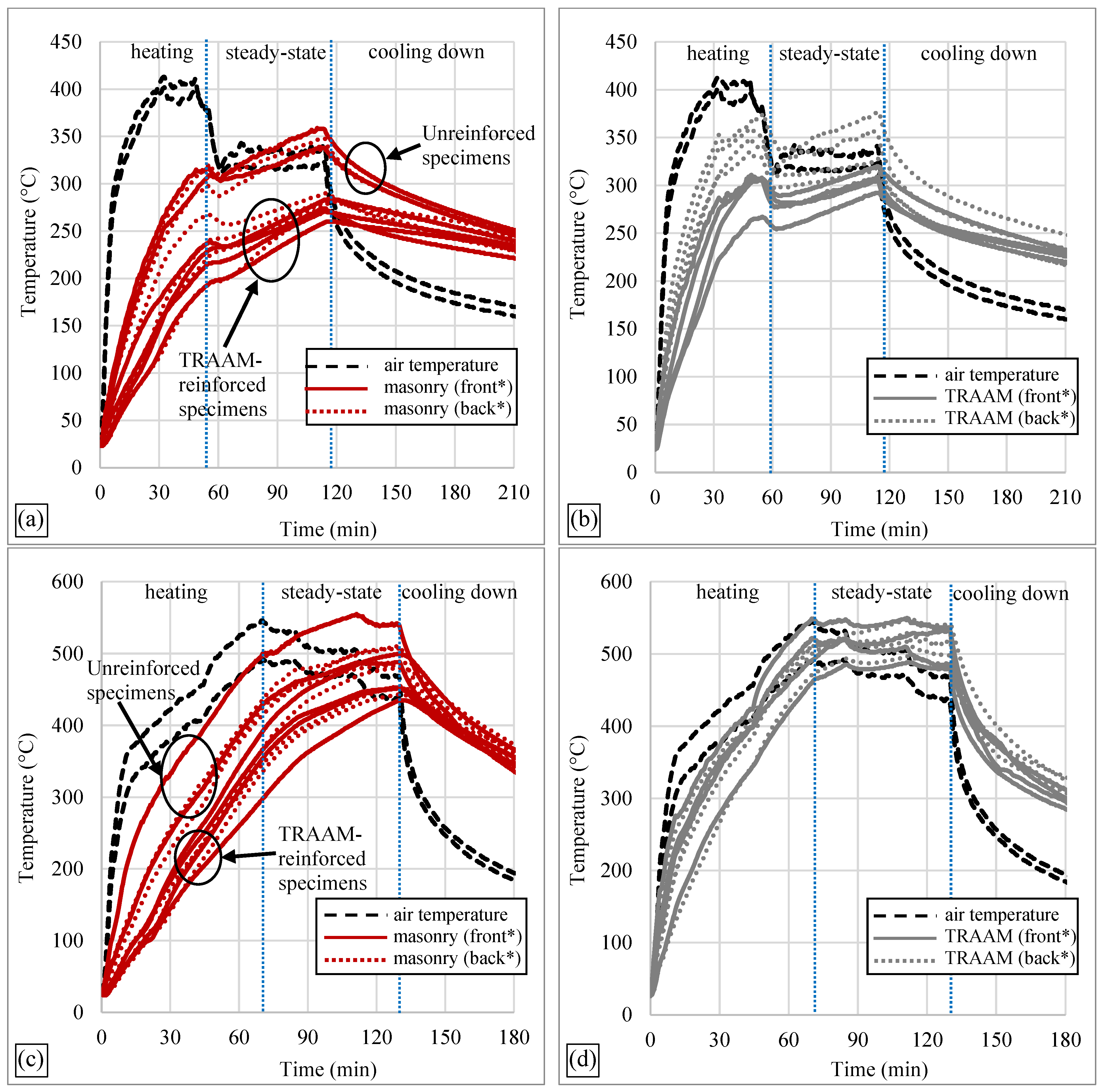
2.3. Heating Regime and Instrumentation

The heating regime adopted in this study consisted of the temperature increase phase, the steady-state phase, and the cooling down phase. Fire exposure took place in a vertical furnace with internal dimensions of 3 × 3 × 1.2 m, equipped with 12 gas nozzle mixing burners (each 300 kW) arranged in vertical banks at the sidewalls. The mechanical tests were conducted after the specimens cooled down to room temperature; thus, the investigations concern the residual capacity of the specimens after exposure to fire.
Figure 1a,b show the arrangement of the specimens in the furnace. It is noted that the specimens were exposed to fire from two sides (flames running parallel to the long sides of the wallettes). The other sides (lateral and top) were insulated with mineral wool to minimize any effects of non-uniform heating near the corners. Fire-resistant aerated concrete blocks were placed on top of the wallettes to keep the top layers of mineral wool in place and to prevent the specimens from overturning.
The temperature of the specimens was recorded with embedded K-type thermocouples in two or four positions on each specimen. The unreinforced wallettes were furnished with two thermocouples, one on each side, inserted in a hole 15 mm deep. The holes were opened with a Ø5 mm drill and, after inserting the sensors, they were sealed with cement paste and mineral wool (see Figure 1c). The strengthened wallettes were furnished with one thermocouple on each side that was embedded in a groove (3 mm wide and 100 mm long) carved in the TRAAM layer. The depth of the groove was chosen to be equal to half the thickness of the TRAAM layer (i.e., 4.5 mm for the 1L specimens and 6.5 mm for the 2L specimens). Hence, the temperature of the TRAAM layer was always measured at half thickness. After inserting the sensors, the grooves were filled with cement paste. In addition, the strengthened specimens received another pair of thermocouples each placed in a hole drilled on each side of the walls reaching a depth equal to 15 mm behind the TRAAM-to-masonry interface; thus, the temperature was also measured in the masonry substrate at the same depth as for the unreinforced specimens. The sensors were, in all cases, placed near a corner of the specimens (Figure 1c,d). Two additional thermocouples were used to measure the air temperature near the specimens. These sensors were of the same type as the ones embedded in the specimens, and they were fixed in such a position that their tip (measuring point) was approximately 100 mm above the top of the two intermediate wallettes. The recordings of the air temperature are given in Figure 2.
At the onset of the steady-state stage of the heating sequence, the specimens that were subjected to fire were exposed to a maximum air temperature of approximately 300 °C or 550 °C (respective average values throughout this stage: 320 °C or 480 °C, with the air temperature being difficult to keep constant at 550 °C). The temperature of 550 °C was chosen as an upper limit before completely damaging the unreinforced specimens. This was based on a trial fire test where an unreinforced specimen (manufactured with the same bricks and lime mortar) was exposed to 600 °C. The specimen was severely damaged with cracks forming at almost every brick and joint; hence, the residual capacity of the specimen was practically zero. This is in agreement with EN 1996-1-2 [24], according to which masonry elements with clay units and general purpose mortar have no residual strength at temperatures above 600 °C. The temperature of 300 °C was opted for as an intermediate level of exposure to elevated temperatures. Two specimens per case were kept in ambient conditions until mechanical testing to be used as reference. Two fire exposure sessions were carried out, one for each maximum targeted temperature.
The heating rate of the air temperature in the furnace during the temperature increase phase was chosen to be as close as possible to the rate of the standard cellulosic fire curve (ISO 834-1 [43]). Hence, the heating rate applied was fast to better simulate a fire scenario (~50 °C/min). The steady-state phase initiated when the average temperature in the TRAAM layers reached the target temperatures of 300 °C and 550 °C, respectively. The duration of the steady-state phase was chosen to be equal to approximately 60 min to provide enough time for potential phase changes in the TRAAM material. After the steady-state phase, the fire exposure was terminated, and the specimens were kept in the furnace (with the furnace door closed) until they naturally cooled down to room temperature. The time history of temperatures during the two fire tests that were conducted is given in Figure 2 (Figure 2a,c include readings from both the Un_T300 and the Un_T550 test groups, respectively).

2.4. Mechanical Test Set up

Diagonal tension (shear) tests were carried out to assess the residual tensile (shear) response of the specimens after fire exposure. The tests were conducted based on the ASTM E519/E519M—15 Standard [44] (deviations being specimens’ dimensions and number of specimens per test group). The load was applied via a servo-hydraulic piston with a total capacity of 500 kN. Figure 3 gives an overview of the mechanical test setup. The horizontal steel beams were placed to prevent any out-of-plane movement. It is noted that the holes and grooves made to embed the thermocouples in the fire-exposed specimens were, in all cases, found at one of the corners of the wallettes that were not to be fixed in the metallic “shoe” supports.
High-contrast lines were formed with black and white paint sprayed on the specimens at the positions shown in Figure 3. These lines were used to monitor the deformation of the specimens along the horizontal and the vertical direction via video-extensometers. The latter comprised high resolution cameras; the related software calculated strains with an accuracy of at least 0.0025%. Measurements were taken only on one side of the specimens. The other side was painted white to allow for a better visualization of the crack patterns.

2.5. Response Surface Formulations

The experimental matrix was designed to study the effect of two factors, namely the exposure temperature and the area of textile reinforcement. For this purpose, a two-factor interaction (2FI) response surface model was created using Design Expert software v11.1.2.0 (Stat-Ease Inc., Minneapolis, MN, USA). The model was built based on 14 runs. The factors were chosen as discrete numerals with three levels. Factor A: temperature levels corresponding to 20 °C, 300 °C and 550 °C. Factor B: area of textile reinforcement applied per side perpendicular to the bed joints and nominally set to 0 mm2, 33.6 mm2 and 67.2 mm2.

3. Results and Discussion

3.1. Observations Regarding Fire Exposure

Unreinforced wallettes showed vertical cracking in the bricks because of high thermal load. They did not survive their transportation to the test rig or all handling actions necessary (rotating) to fit the “shoe” supports. No visible thermal cracks were observed on the reinforced specimens. Upon inspecting Figure 2 (end of the T300 steady-state heating stage), it can be noticed that—on average—the TRAAM jackets (10–14 mm thick) were able to provide some thermal shielding for the masonry faces (unreinforced versus reinforced masonry: temperature difference at a depth equal to 15 mm behind the TRAAM–masonry interface ~70 °C). This shielding effect was lost in the T550 test specimens, for which the heating period up to the onset of the steady-state heating stage took longer than in the case of the T300 ones.

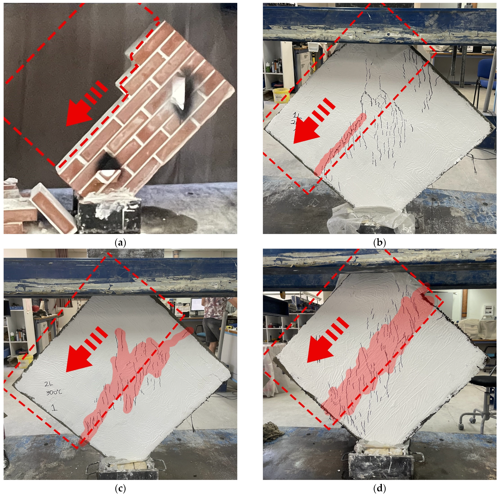
3.2. Observations Regarding Diagonal Shear Tests

The experimental shear stress–strain curves for all specimens tested are shown in Figure 4. The ascending branch of the curves remains linear up to a stress level equal to 60–70% of the maximum shear stress achieved. During this stage, composite action is still intact and the reinforced wallette remains uncracked. Deviation from linearity denotes the onset of diffused fine vertical cracking along the diagonal compression zone, which was also visible on the jacket’s surface. For most specimens, diffused cracking took place over the central compressed band stretching roughly mid-side to mid-side and excluding the vicinity of the load application areas. This is an indication of the local detachment of the jacket from the wall’s surface due to loading during the crack formation stage.
The test results are presented in Table 2 in terms of the following parameters: (i) peak shear stress (τmax); (ii) shear strain at peak shear stress (γmax); (iii) shear modulus (modulus of rigidity—G = τ/γ); (iv) ultimate shear stress (τu) corresponding to the post-peak shear stress reached at conventional failure (=0.8 τmax); (v) ultimate shear strain (γu) corresponding to (τu); (vi) ‘yield’ shear strain (γy) defined as the abscissa of the intersection point of the two linear branches used to idealize each experimental shear stress–shear strain curve: the slope of the first (ascending) branch is assumed as the secant value to the curve in correspondence to 0.33 τmax and the second (flat) line crosses the vertical (shear stress) axis at τmax; and (vii) pseudo-ductility (or else apparent ductility, μ) computed as the (γuy) ratio. Based on [44], shear stresses (τ, in MPa) were calculated using the following formula: τ = 0.707 P/An, where P is the applied load and An is the net area of the wall taken as An = [(w + h) × t × n]/2, with w and h being the width and height of the wall, respectively, t being the total thickness of the wall and n the percentage of the gross area taken as solid (100%, for all walls, in this study). Shear strains (γ) were computed as (ΔV + ΔH)/g, where ΔV and ΔH are the vertical shortening and the horizontal expansion of the wall, respectively, and g is the gage length (equal for both ΔV and ΔH). Finally, Δτmax, ΔG and Δμ in Table 2 stand for the relative changes in the average values of τmax, G and μ of each test group from the respective values of the Un_T20 one.
Underlined values of shear modulus in Table 2 (being unexpectantly lower than the ones of identical specimens within the same test group) were ignored in the calculation of average values. A careful inspection of all specimens before testing indeed revealed local detachments of the TRAAM jackets found along the perimeter of the wallettes, resulting in low shear modulus values. This could be due to either edge thermal effects or damage during specimens’ transportation from the furnace to the test frame. Interestingly, the same values were identified as outliers by using the software for the derivation of the response surface models (see Section 3.3). G value underlining was inevitably carried over to the respective pseudo-ductility ones. Specimen 2L_T550_b—although of a relatively comparable G value to the one of its homologous specimen—deviated from the complete flatness prior to mechanical testing and failed prematurely.
The failure mode of the unreinforced samples was dominated by typical sliding shear cracks traveling through the bed and head joints (Figure 5a) along the brick–mortar interface, which suggested a poor bond. Mezrea et al. [10] reported similar failure modes after testing specimens of historical masonry wallettes in diagonal tension. The failure mode of the reinforced specimens (unfired and fired, alike, excluding those with defects prior to testing) can be described as a combination of diagonal cracking, top mortar delamination and bulging, and (for the 2L systems) extensive debonding of the TRAAM jacket from the walls’ faces (Figure 5). No crushing of the corners was observed.
As with all textile-based strengthening schemes (e.g., see Marcari et al. [45] and Parisi et al. [46]), a remarkable increase in shear strength was also recorded with the type of textile-reinforced mortar jacket employed in this study, regardless of the numbers of textile reinforcements applied and the exposure temperature opted for. Compared to unreinforced/unfired specimens, the unfired wallettes reinforced with GFNS-based jackets resulted in a substantial increase in peak shear stress (by 260% and 335%, for single- and double-layered systems, respectively). Also, fire-inflicted specimens—compared with the unreinforced/unfired ones—failed at much larger shear stress values (increases reaching 240% and 200% for single-layered systems exposed to 300 °C and 550 °C, respectively, and 290% for double-layered systems regardless of exposure temperature). Gains from doubling of the textile reinforcement were rather moderate (20%, 15% and 30% for unfired, fired_@300 °C and fired_@550 °C specimens, respectively). Finally, exposure to the time-temperature histories resulted in a minimal shear strength loss of the strengthened specimens compared to their unfired counterparts, which was less than 15% for all cases. It can be stated that—for the time–temperature profiles applied in this work—the GFNS mortar retains the largest part of its stress transfer and redistribution capacity from the masonry substrate to the carbon textile. In turn, the matrix-to-textile bond capacity remains also rather unaffected by firing. It is interesting to note that the thermal distress of the composite is alleviated by the fact that both materials (mortar and textile) share the same thermal deformation sign: mortar exhibits thermal shrinkage during heating (within the temperature range applied in this work), whereas carbon fibers also shrink at elevated temperatures in the longitudinal direction [47]. Finally, it is probable that carbon fibers did suffer some localized oxidation-induced thermal damage when their temperature increased above 400 °C (T550 specimens’ case); damage localization would coincide with thermal cracks where the fibers came in contact with air. Although thermal cracking was not detected on the walls’ surface prior to mechanical testing, it is possible that cracks had closed during the cooling down stage.
Compared to unreinforced/unfired specimens, the unfired wallettes reinforced with GFNS-based jackets resulted in an increase in the shear modulus amounting to approximately 25% and 40% for single- and double-layered systems, respectively. Nevertheless, subjecting these specimens to fire resulted in (i) cancelling of the stiffness gains for all T300 specimens (both single- and double-layered ones) and (ii) a considerable decrease in the T550 specimens’ rigidity (the decrease being larger for lower reinforcement quantities: 65% and 45% for 1L and 2L specimens, respectively). The doubling of the textile reinforcement led to a rather moderate increase in the shear modulus of unfired and T300 specimens (approximately 15% and 20%, respectively); the respective gain for specimens exposed to 550 °C was equal to approximately 60%. That is, for high thermal loads, the outer TRAAM layer offers protection against thermal damage to the inner one. Finally, exposure to the time-temperature histories resulted in either moderate or substantial losses in the rigidity of strengthened specimens compared to their unfired counterparts (approximately 25% and 60–70% for single- and double-layered systems, respectively). This indicates (and verifies the above-speculated) temperature-induced damage (such as thermal cracking, localized fibers’ damage and—possibly—TRM/masonry interfacial cracking due to differential thermal strains at the interface).
All strengthened specimens, regardless of the number of reinforcing layers and exposure temperature, achieved pseudo-ductility scores that ranged between 1.7 and 5 times the one of the unreinforced/unfired wallettes (based on average group values). This shows that, even after a high thermal load (550 °C, for more than 1 h), the TRAAM jacket is still able to contribute to a residual deformation capacity increase and prevent the brittle collapse of the masonry wall. The doubling of the textile reinforcement led to a negligible change in the pseudo-ductility of unfired specimens (note that the thickness of the jacket did not increase proportionally to the number of textile layers). Finally, the heating of the reinforced specimens following the T300 time-temperature history bore a negligible effect on their residual pseudo-ductility compared to unheated reinforced walls. On the contrary, exposure to the T550 time-temperature history caused a significant pseudo-ductility drop (approximately 50%) for both reinforcement contents.
The post-failure inspection of the TRAAM layers showed a mixed failure mechanism where (apart from diagonal cracking) debonding between the GFNS-based jacket and the masonry substrate appears simultaneously with the failure of the textile–matrix interface (Figure 6a). Figure 6b shows carbon fiber bundles that have failed due to diagonal tension. A close examination of the textile shows that fibers did not fail simultaneously but rather gradually, accompanied by the progressive slippage of the fibers within the matrix; the slippage of fibers might be responsible for the soft decrease in shear resistance characterized by a quasi-horizontal behavior in the stress–stain curves reported in Figure 4. This pseudo-plasticity was slightly more pronounced in the one-layer specimens than in the wallettes reinforced with two layers. It is possible that the double-layer specimens possessed slightly better fiber-to-matrix bonding due to the larger mortar supply and higher degree of mortar penetration in the yarns. The latter could have been a result of the pressure generated by the operator during the application of the second textile layer which, in turn, might have promoted mortar penetrability into the yarns of the first textile layer. The pseudo-yielding of the TRAAM-reinforced masonry wallettes represent an important advantage over unreinforced systems in the context of earthquake-vulnerable zones, where unreinforced systems tend to present a brittle type of failure [11].

3.3. Response Surface Models

Two-factor response surface models were generated to establish the relationship between the selected predictor variables—namely, exposure temperature and reinforcement quantity—and the response ones comprising residual mechanical properties, such as the peak shear stress (Equation (1)), the shear modulus (Equation (2)) and the pseudo-ductility (Equation (3)). The fit statistics for these models are reported in Table 3. For each model, Table 3 includes the mean value, the standard deviation, the coefficient of variation (CoV), different forms of the coefficient of determination (R2) and the adequate precision. The adjusted and predicted R2 were found to be in good agreement with each other with a difference of less than 20%. The adequate precision metric was higher than four for all cases, which indicates a strong (80%) probability that the variations in the measured responses are a product of the variables A and B instead of natural variation (commonly known as noise).
τmax = 0.298 − 0.000257 × A + 0.0300 × B − 0.000235 × B2
G = 2479 − 3.76 × A + 15.0 × B
μ = 4.73 − 0.0428 × A + 0.960 × B − 0.000102 × A × B − 0.000114 × A2 − 0.00926 × B2
where:
  • τmax: peak shear stress (MPa);
  • G: shear modulus (MPa);
  • μ: pseudo-ductility;
  • A: temperature (°C);
  • B: area of carbon textile reinforcement (mm2).
The models were constructed using the data provided in Table 2. Data were input into the Design Expert® v11.1.2.0 software. The data entries were checked for outliers using normal plots, Cook’s distance plots and Residual versus Predicted values. Three outliers for G values were identified (as previously mentioned) and these are underlined in Table 2 (see specimens 2L_T20_a, 1L_T300_b and 2L_T300_b).

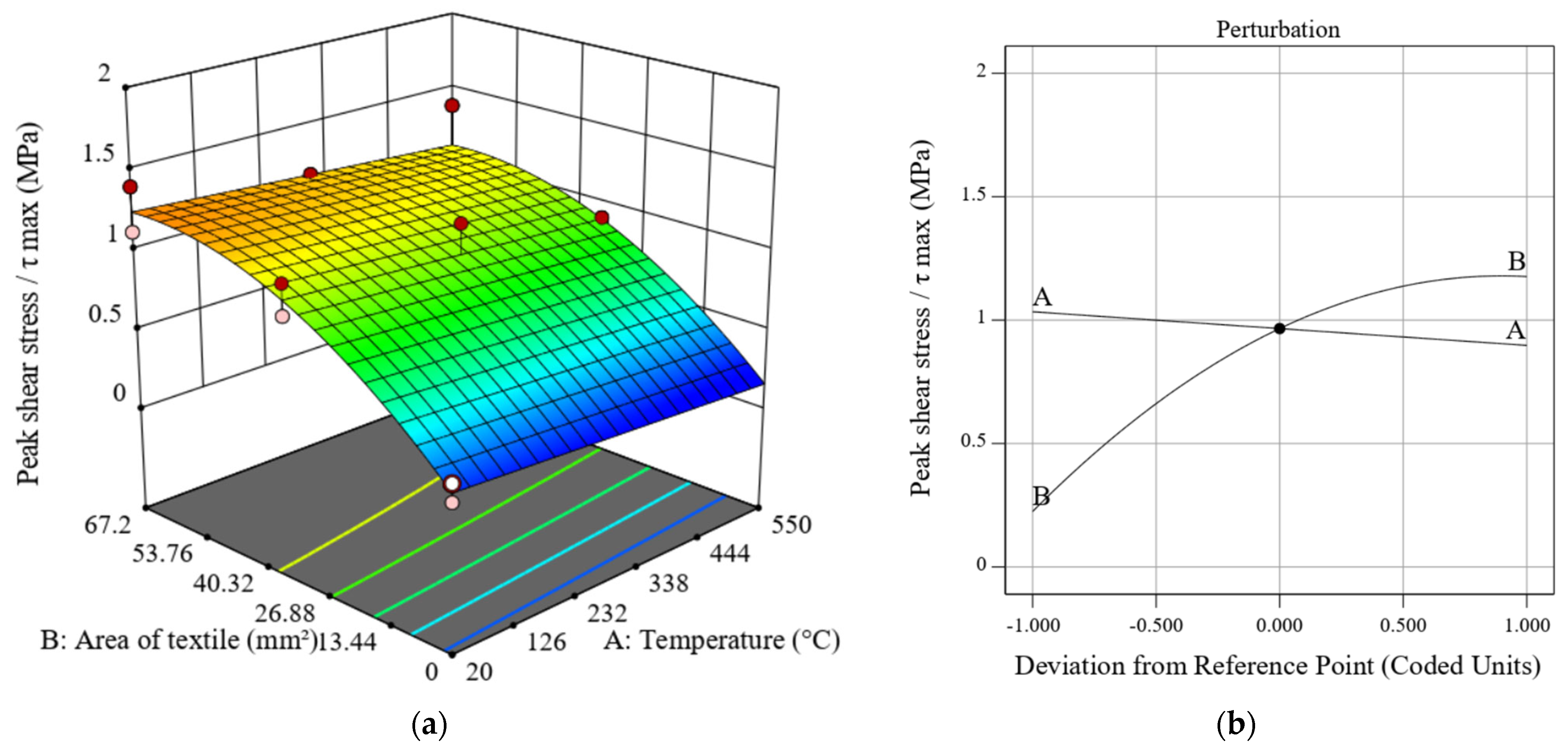
3.3.1. Peak Shear Stress

The response surface model presented in Figure 7a allows for a visualization of the influence of both the area of carbon textile and temperature in the peak shear stress values of the wallettes. As seen in Figure 7, there seems to be a quadratic relationship between the area of reinforcement and the peak shear stress regardless of exposure temperature. The trend indicates that a further increase in textile reinforcement (for example, adding a third layer or increasing the size of the fiber bundles) would likely not result in a further increase in the peak shear strength. The perturbation plot for peak shear stress (Figure 8b) allows for comparing the effect of temperature and area of reinforcement. The plot shows the influence of changing one parameter and leaving the other one fixed. As observed in the 3D surface plot, the perturbation graph shows the quadratic relationship between the reinforcement amount and peak shear stress. The plot indicates the slight influence of temperature, denoted by the almost horizontal A factor line (A standing for temperature).

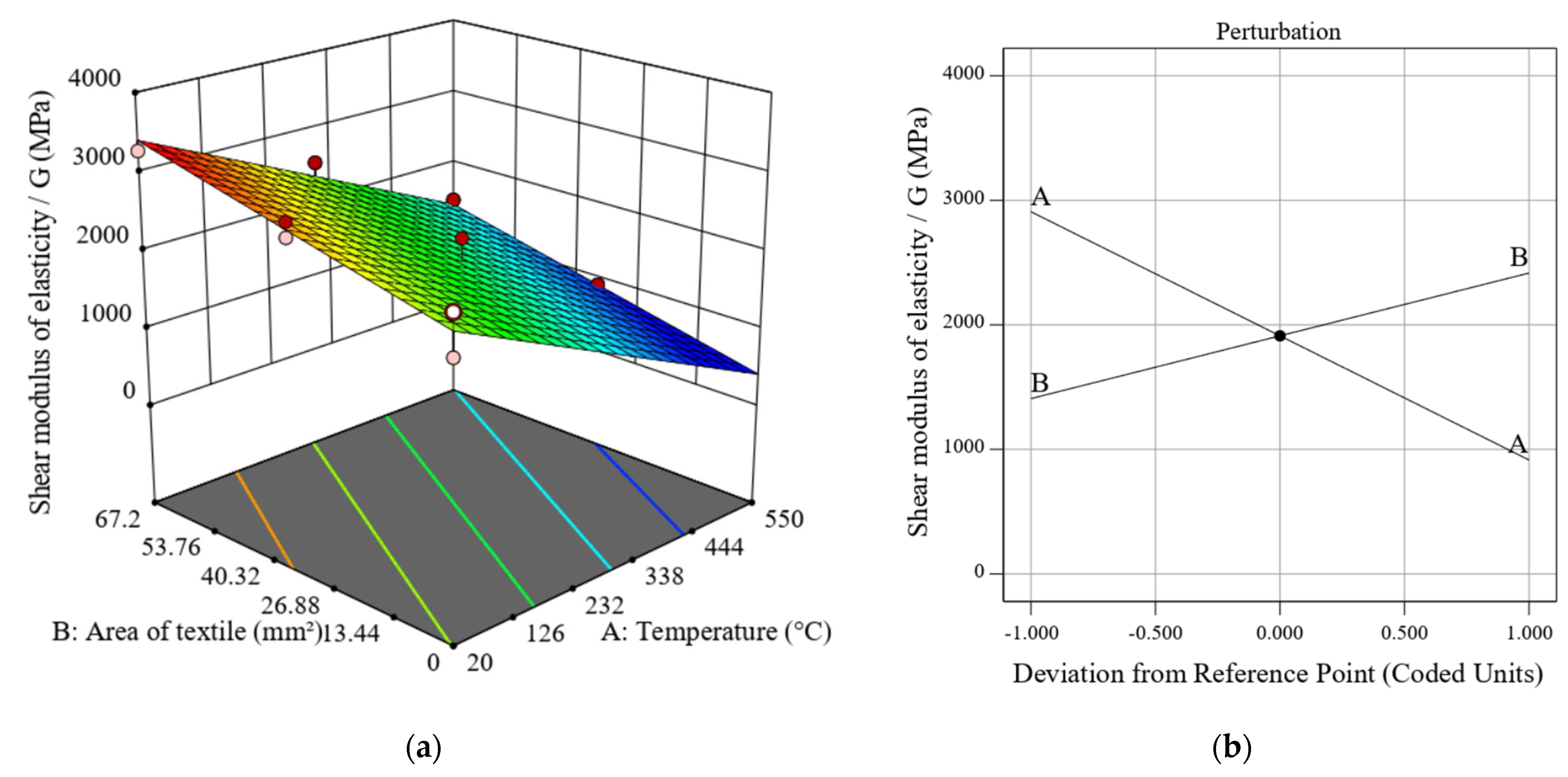
3.3.2. Shear Modulus

As observed in Figure 8a, the relationship between shear modulus and factors A and B is best approximated by a linear relationship. The perturbation plot in Figure 8b shows that, while both variables A and B influenced the stiffness of the masonry wallettes, Factor A (temperature) has a slightly higher influence, as evidenced by the higher slope of the A line.

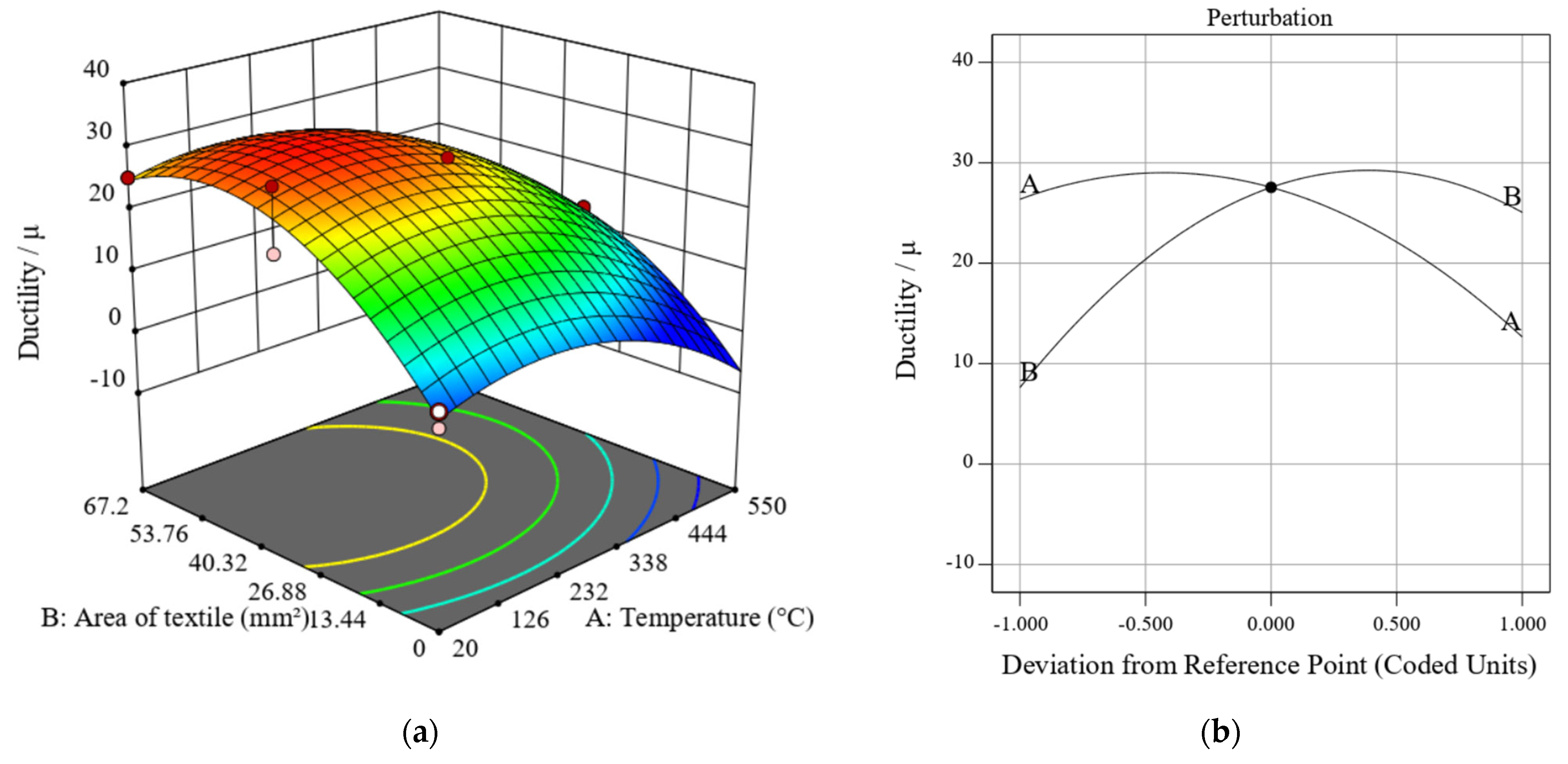
3.3.3. Pseudo-Ductility

The relationship between the reinforcement amount and the temperature is described by the 3D response surface plotted in Figure 9. There is a quadratic relationship between these two factors and the pseudo-ductility of the wallettes, owing to the influence of temperature in affecting the stiffness of the wallettes and the previously proven influence of the area of textile reinforcement on the stiffness and peak shear stress of the wallettes. The plot shows that, similar to the case of peak shear stress, there is a pseudo-ductility ceiling value gained at the highest level of reinforcement; it is unlikely (according to the regression model) that a further increase in pseudo-ductility would be produced by an increase in the amount of carbon textile reinforcement. The 3D plot shows the higher influence of temperature at low levels of reinforcement. This can be associated with the insulating effect of the GFNS mortar. As the number of layers was increased from one to two, the thickness of the mortar was also increased, resulting in more mortar insulating both the masonry wall and the carbon textile reinforcement. The insulating effect is provided both by the GFNS matrix, as reported by Sakkas et al. [36], and by the FNS fine aggregate according to the results of Saha et al. [48], who reported that the thermal conductivity of OPC mortars decreased from 2.34 W/mK to 1.65 W/mK and 1.16 W/mK by substituting silica sand with FNS sand by 50% and 100%, respectively. The perturbation plot provided in Figure 9 shows the influence of both temperature and area of textile in the pseudo-ductility of these wallettes. The effect is nonlinear and indicates that, while high exposure temperature does not seem to affect the peak shear strength, it does result in a decrease in pseudo-ductility.

4. Conclusions

A textile-reinforced alkali-activated mortar (TRAAM) based on ferronickel slag was tested for its potential as a retrofitting technique to increase the shear capacity of historical masonry wallettes. The diagonal shear tests were executed on unreinforced/unfired, TRAAM-reinforced/unfired and TRAAM-reinforced/fired walls. The reinforcement comprised bilateral carbon fiber TRAAM jackets with either a single or a double layer of textile. Fired specimens (all exposing both strengthened faces to fire) were subjected to a fast temperature rising ramp (~50 °C/min) followed by an hour-long steady-state exposure at average TRAAM surface temperatures of 300 °C and 550 °C. The following main conclusions can be drawn from this work:
  • The time-temperature histories imposed on all reinforced specimens bore no visible thermal cracks.
  • The unreinforced/unfired masonry wallettes failed due to sliding shear, whereas the ones reinforced with bilateral TRAAM jackets (unfired and fired alike, excluding those with defects prior to testing) failed due to a combination of diagonal cracking and delamination/bulging of the top mortar layer. For double-layered systems, the extensive debonding of the TRAAM jacket from the walls’ faces also took place during failure. Future relevant experimental campaigns should take measures to avoid thermal edge effects (during both heating and cooling down) that may lead to the detachment of the jackets along the perimeter of the specimens.
  • Compared to unreinforced/unfired specimens, the unfired wallettes reinforced with GFNS-based jackets resulted in a substantial increase in peak shear stress (by 260% and 335%, for single- and double-layered systems, respectively). Fire-inflicted TRAAM-reinforced specimens—compared with the unreinforced/unfired ones— failed at much larger shear stress values (with increases reaching 240% and 200% for single-layered systems exposed to 300 °C and 550 °C, respectively, and 290% for double-layered systems regardless of exposure temperature). This means that—compared to their jacketed/unfired counterpart specimens—exposure to the time-temperature histories applied in this work resulted in a minimal shear strength loss of the jacketed specimens, which was less than 15% for all cases.
  • Compared to unreinforced/unfired specimens, the unfired wallettes reinforced with GFNS-based jackets resulted in an increase in shear modulus amounting to approximately 25% and 40% for single- and double-layered systems, respectively. The fire scenarios imposed on these specimens resulted in (i) the cancellation of any stiffness gains when heating at 300 °C (i.e., the shear modulus of strengthened/fired specimens was comparable to that of unreinforced/unfired ones or—equivalently—it was reduced by approximately 25% with regards to reinforced/unfired specimens for both reinforcement ratios) and (ii) a considerable decrease in the specimens’ rigidity when heating at 550 °C (the decrease being larger for lower reinforcement quantities: 65% and 45% for 1L and 2L specimens, respectively or—equivalently—being equal to 60–70% with regards to reinforced/unfired specimens for both reinforcement ratios). Therefore, heating adversely affects the rigidity of TRAAM-reinforced walls to a much larger extend than it does the strength.
  • Shear strength gains from doubling of the textile reinforcement were rather moderate (20%, 15% and 30% for unfired, fired_@300 °C and fired_@550 °C specimens, respectively).
  • Even after exposure to a high thermal load (550 °C, for more than 1 h), the TRAAM jacket was still able to contribute to a residual deformation capacity increase (compared to unreinforced/unfired walls) and prevent the brittle collapse of the masonry wall. Compared to reinforced/unfired walls, heating at 300 °C bore a negligible effect on the residual pseudo-ductility; on the contrary, heating at 550 °C caused a significant pseudo-ductility drop (approximately 50%) for both reinforcement ratios.
  • The 3D response surface and perturbation plots show the higher dependency of the peak shear stress upon the reinforcement amount rather than on the temperature. The shear modulus and the pseudo-ductility, on the other hand, are almost equally influenced by these parameters.
  • Based on the above, the authors support that the prospect of using alkali-activated mortars for repair and strengthening applications, when close-to-initial residual capacity after high temperature exposure is desired, seems very promising.

Author Contributions

Conceptualization, A.A., P.K., C.G.P. and T.C.T.; methodology, A.A., P.K., C.G.P. and T.C.T.; software, A.A.; validation, C.G.P. and T.C.T.; formal analysis, A.A. and P.K.; investigation, A.A.; resources, C.G.P. and T.C.T.; data curation, A.A. and C.G.P.; writing—original draft preparation, A.A. and P.K.; writing—review and editing, A.A., P.K., C.G.P. and T.C.T.; visualization, A.A. and C.G.P.; supervision, C.G.P. and T.C.T.; project administration, C.G.P. and T.C.T.; funding acquisition, C.G.P. and T.C.T. All authors have read and agreed to the published version of the manuscript.

Funding

This research was funded by the European Union’s H2020 MARIE SKODOWSKA-CURIE ACTIONS, grant agreement No. 813596 DuRSAAM. The APC was funded by the University of Patras.

Data Availability Statement

Data are contained within the article.

Acknowledgments

We thank the company LARCO for the kind donation of ferronickel slag. Special acknowledgement is given to the Laboratory of Sedimentology and to the Laboratory of Electron Microscopy and Microanalysis of the University of Patras.

Conflicts of Interest

The authors declare no conflicts of interest. The funders had no role in the design of the study; in the collection, analyses, or interpretation of data; in the writing of the manuscript; or in the decision to publish the results.

References

  1. Bon, R.; Crosthwaite, D. The Future of International Construction; Thomas Telford: London, UK, 2000. [Google Scholar]
  2. Peled, A.; Bentur, A. Geometrical characteristics and efficiency of textile fabrics for reinforcing cement composites. Cem. Concr. Res. 2000, 30, 781–790. [Google Scholar] [CrossRef]
  3. Peled, A.; Mobasher, B. Pultruded fabric-cement composites. ACI Mater. J. 2005, 102, 15. [Google Scholar]
  4. Kariou, F.A.; Triantafyllou, S.P.; Bournas, D.A. TRM strengthening of masonry arches: An experimental investigation on the effect of strengthening layout and textile fibre material. Compos. Part B Eng. 2019, 173, 106765. [Google Scholar] [CrossRef]
  5. Papanicolaou, C.G.; Triantafillou, T.C.; Karlos, K.; Papathanasiou, M. Textile-reinforced mortar (TRM) versus FRP as strengthening material of URM walls: In-plane cyclic loading. Mater. Struct. 2007, 40, 1081–1097. [Google Scholar] [CrossRef]
  6. Prota, A.; Marcari, G.; Fabbrocino, G.; Manfredi, G.; Aldea, C. Experimental in-plane behavior of tuff masonry strengthened with cementitious matrix–grid composites. J. Compos. Constr. 2006, 10, 223–233. [Google Scholar] [CrossRef]
  7. Triantafillou, T.C.; Karlos, K.; Kapsalis, P.; Georgiou, L. Innovative structural and energy retrofitting system for masonry walls using textile reinforced mortars combined with thermal insulation: In-plane mechanical behavior. J. Compos. Constr. 2018, 22, 04018029. [Google Scholar] [CrossRef]
  8. Kouris, L.A.S.; Triantafillou, T.C. State-of-the-art on strengthening of masonry structures with textile reinforced mortar (TRM). Constr. Build. Mater. 2018, 188, 1221–1233. [Google Scholar] [CrossRef]
  9. Parisi, F.; Menna, C.; Prota, A. Fabric-reinforced cementitious matrix (FRCM) composites: Mechanical behavior and application to masonry walls. Fail. Anal. Biocomposites Fibre-Reinf. Compos. Hybrid Compos. 2019, 199–227. [Google Scholar] [CrossRef]
  10. Mezrea, P.E.; Ispir, M.; Balci, I.A.; Bal, I.E.; Ilki, A. Diagonal tensile tests on historical brick masonry wallets strengthened with fabric reinforced cementitious mortar. Structures 2021, 33, 935–946. [Google Scholar] [CrossRef]
  11. Ungureanu, D.; Țăranu, N.; Ghiga, D.A.; Isopescu, D.N.; Mihai, P.; Cozmanciuc, R. Diagonal tensile test on masonry panels strengthened with textile-reinforced mortar. Materials 2021, 14, 7021. [Google Scholar] [CrossRef]
  12. Bazli, M.; Abolfazli, M. Mechanical properties of fibre reinforced polymers under elevated temperatures: An overview. Polymers 2020, 12, 2600. [Google Scholar] [CrossRef] [PubMed]
  13. Kapsalis, P.; Triantafillou, T.; Korda, E.; Van Hemelrijck, D.; Tysmans, T. Tensile performance of textile-reinforced concrete after fire exposure: Experimental investigation and analytical approach. J. Compos. Constr. 2022, 26, 04021067. [Google Scholar] [CrossRef]
  14. Tran, T.T.; Kang, H.; Kwon, H.M. Effect of heat curing method on the mechanical strength of alkali-activated slag mortar after high-temperature exposure. Materials 2021, 12, 1789. [Google Scholar] [CrossRef] [PubMed]
  15. Rambo, D.A.S.; de Andrade Silva, F.; Toledo Filho, R.D.; Gomes, O.D.F.M. Effect of elevated temperatures on the mechanical behavior of basalt textile reinforced refractory concrete. Mater. Des. 2015, 65, 24–33. [Google Scholar] [CrossRef]
  16. Colombo, I.; Colombo, M.; Magri, A.; Zani, G.; di Prisco, M. Textile reinforced mortar at high temperatures. Appl. Mech. Mater. 2011, 82, 202–207. [Google Scholar] [CrossRef]
  17. Homoro, O.; Vu, X.H.; Ferrier, E. Experimental and analytical study of the thermo-mechanical behaviour of textile-reinforced concrete (TRC) at elevated temperatures: Role of discontinuous short glass fibres. Constr. Build. Mater. 2018, 190, 645–663. [Google Scholar] [CrossRef]
  18. Saidi, M.; Vu, X.H.; Ferrier, E. Experimental and analytical analysis of the thermomechanical behaviour at elevated temperature of the textile reinforced concrete (TRC) effect of the hydric state. In Proceedings of the 9th International Conference on Fibre-Reinforced Polymer (FRP) Composites in Civil Engineering, Paris, France, 17–19 July 2018. [Google Scholar]
  19. Kapsalis, P.; Tysmans, T.; Van Hemelrijck, D.; Triantafillou, T. State-of-the-Art Review on Experimental Investigations of Textile-Reinforced Concrete Exposed to High Temperatures. J. Compos. Sci. 2021, 5, 290. [Google Scholar] [CrossRef]
  20. Russo, S.; Sciarretta, F. Experimental and theoretical investigation on masonry after high temperature exposure. Exp. Mech. 2012, 52, 341–359. [Google Scholar] [CrossRef]
  21. Russo, S.; Sciarretta, F. Masonry exposed to high temperatures: Mechanical behaviour and properties—An overview. Fire Saf. J. 2013, 55, 69–86. [Google Scholar] [CrossRef]
  22. Daware, A.; Naser, M.Z. Fire performance of masonry under various testing methods. Constr. Build. Mater. 2021, 289, 123183. [Google Scholar] [CrossRef]
  23. Andreini, M.; Sassu, M. Mechanical behaviour of full unit masonry panels under fire action. Fire Saf. J. 2011, 46, 440–450. [Google Scholar] [CrossRef]
  24. British Standards Institution. Eurocode 2: Design of Concrete Structures: British Standard; British Standards Institution: London, UK, 2008. [Google Scholar]
  25. Maroudas, S.R.; Papanicolaou, C.C.G. Effect of high temperatures on the TRM-to-masonry bond. Key Eng. Mater. 2017, 747, 533–541. [Google Scholar] [CrossRef]
  26. Askouni, P.D.; Papanicolaou, C.C.G.; Kaffetzakis, M.I. The effect of elevated temperatures on the TRM-to-masonry bond: Comparison of normal weight and lightweight matrices. Appl. Sci. 2019, 9, 2156. [Google Scholar] [CrossRef]
  27. Askouni, P.D.; Papanicolaou, C.C.G.; Azdejkovic, L. Experimental investigation of the trm-to-masonry bond after exposure to elevated temperatures: Cementitious and alkali-activated matrices of various densities. Materials 2021, 15, 140. [Google Scholar] [CrossRef]
  28. Iorfida, A.; Candamano, S.; Crea, F.; Ombres, L.; Verre, S.; de Fazio, P. Bond behaviour of FRCM composites: Effects of high temperature. Key Eng. Mater. 2019, 817, 161–166. [Google Scholar] [CrossRef]
  29. Triantafillou, T.C.; Karlos, K.; Kefalou, K.; Argyropoulou, E. An innovative structural and energy retrofitting system for URM walls using textile reinforced mortars combined with thermal insulation: Mechanical and fire behavior. Constr. Build. Mater. 2017, 133, 1–13. [Google Scholar] [CrossRef]
  30. Estevan, L.; Torres, B.; Varona, F.B.; Baeza, F.J.; Ivorra, S. Shear strengthening of masonry walls with Textile Reinforced Mortars (TRM) under high temperature exposure. J. Build. Eng. 2023, 63, 105511. [Google Scholar] [CrossRef]
  31. Duxson, P.; Provis, J.L.; Lukey, G.C.; Van Deventer, J.S. The role of inorganic polymer technology in the development of ‘green concrete’. Cem. Concr. Res. 2007, 37, 1590–1597. [Google Scholar] [CrossRef]
  32. Arce, A.; Komkova, A.; Van De Sande, J.; Papanicolaou, C.G.; Triantafillou, T.C. Optimal Design of Ferronickel Slag Alkali-Activated Material for High Thermal Load Applications Developed by Design of Experiment. Materials 2022, 15, 4379. [Google Scholar] [CrossRef]
  33. Scrivener, K.L.; Kirkpatrick, R.J. Innovation in use and research on cementitious material. Cem. Concr. Res. 2008, 38, 128–136. [Google Scholar] [CrossRef]
  34. Mehta, P.K. High-performance, high-volume fly ash concrete for sustainable development. In Proceedings of the International Workshop on Sustainable Development and Concrete Technology, Iowa State University, Ames, IA, USA, 20 May 2004. [Google Scholar]
  35. Rickard, W.D.; Gluth, G.J.; Pistol, K. In-situ thermo-mechanical testing of fly ash geopolymer concretes made with quartz and expanded clay aggregates. Cem. Concr. Res. 2016, 80, 33–43. [Google Scholar] [CrossRef]
  36. Sakkas, K.; Nomikos, P.; Sofianos, A.; Panias, D. Utilisation of FeNi-Slag for the production of inorganic polymeric materials for construction or for passive fire protection. Waste Biomass Valorizat. 2014, 5, 403–410. [Google Scholar] [CrossRef]
  37. Larco General Mining & Metallurgical Co. S.A. Research and Development. Available online: http://www.larco.gr/rnd.php (accessed on 1 September 2022).
  38. Komnitsas, K.; Zaharaki, D.; Perdikatsis, V. Geopolymerisation of low calcium ferronickel slags. J. Mater. Sci. 2007, 42, 3073–3082. [Google Scholar] [CrossRef]
  39. Meredith, S. A Sand Shortage? The World Is Running Out of a Crucial—But Under-Appreciated—Commodity. Available online: https://www.cnbc.com/2021/03/05/sand-shortage-the-world-is-running-out-of-a-crucial-commodity.html (accessed on 1 July 2023).
  40. Thompson, A.; Saha, A.K.; Sarker, P.K. Comparison of the alkali-silica reactions of ferronickel slag aggregate in fly ash geopolymer and cement mortars. Eur. J. Environ. Civ. Eng. 2022, 26, 891–904. [Google Scholar] [CrossRef]
  41. Arce, A.; Le Galliard, C.; Komkova, A.; Papanicolaou, C.G.; Triantafillou, T.C. Optimal design of ferronickel slag alkali-activated mortar for repair exposed to high thermal load. Mater. Struct. 2023, 56, 34. [Google Scholar] [CrossRef]
  42. EN 1015-11; Methods of Test for Mortar for Masonry–Part 11: Determination of Flexural and Compressive Strength of Hardened Mortar. European Committee for Standardization: Brussels, Belgium, 1999.
  43. ISO 834-1; Fire Resistance Tests-Elements of Building Construction. International Organization for Standardization: Geneva, Switzerland, 1999.
  44. ASTM E519-02; Standard Test Method for Diagonal Tension (Shear) in Masonry Assemblages. ASTM International: West Conshohocken, PA, USA, 2002.
  45. Marcari, G.; Basili, M.; Vestroni, F. Experimental investigation of tuff masonry panels reinforced with surface bonded basalt textile-reinforced mortar. Compos. Part B Eng. 2017, 108, 131–142. [Google Scholar] [CrossRef]
  46. Parisi, F.; Iovinella, I.; Balsamo, A.; Augenti, N.; Prota, A. In-plane behaviour of tuff masonry strengthened with inorganic matrix–grid composites. Compos. Part B Eng. 2013, 45, 1657–1666. [Google Scholar] [CrossRef]
  47. Kude, Y.; Sohda, Y. Thermal management of carbon-carbon composites by functionally graded fiber arrangement technique. Funct. Graded Mater. 1997, 239–244. [Google Scholar] [CrossRef]
  48. Saha, A.K.; Sarker, P.K.; Golovanevskiy, V. Thermal properties and residual strength after high temperature exposure of cement mortar using ferronickel slag aggregate. Constr. Build. Mater. 2019, 199, 601–612. [Google Scholar] [CrossRef]
Figure 1. (a) Overview of six specimens prepared for fire exposure; (b) top-view sketch with temperature measuring positions through the thickness of the strengthened specimens; (c) embedded thermocouple in an unreinforced wallette; (d) embedded thermocouples in a reinforced specimen.
Jcs 08 00014 g001
Figure 2. Temperature recordings during fire exposure with a target temperature of 300 °C [(a,b)] and 550 °C [(c,d)]; temperatures in masonry [(a,c)]; and TRAAM [(b,d)]. * Front: facing towards the furnace door; back: facing towards the back wall and gas extraction of the furnace.
Jcs 08 00014 g002
Figure 3. Diagonal compression test setup (a) of an unreinforced wallette; (b) of a reinforced wallette.
Jcs 08 00014 g003
Figure 4. Shear stress–strain curves for the wallettes reinforced with (a) one layer of reinforcement; (b) two layers of reinforcement (specimens with defects prior to mechanical testing resulting in either low G values or premature failure are shown with a single or a double asterisk, respectively).
Jcs 08 00014 g004
Figure 5. Shear damage patterns of specimens: (a) Un_T20_a; (b) 1L_T20_a; (c) 2L_T300_a; (d) 1L_T550_a.
Jcs 08 00014 g005
Figure 6. Post-failure inspection of TRAAM showing: (a) debonding along both the brick–mortar and the textile–bottom-mortar-layer interfaces, (b) ruptured carbon fiber bundles.
Jcs 08 00014 g006
Figure 7. (a) 3D response surface model of peak shear stress as a function of factors A (temperature), and B (area of textile reinforcement); (b) perturbation plot of factors A and B.
Jcs 08 00014 g007
Figure 8. (a) 3D response surface model of shear modulus as a function of factors A (temperature), and B (area of textile reinforcement); (b) perturbation plot of factors A and B.
Jcs 08 00014 g008
Figure 9. (a) 3D response surface model of pseudo-ductility as a function of factors A (temperature), and B (area of textile reinforcement); (b) perturbation plot of factors A and B.
Jcs 08 00014 g009
Table 1. Ferronickel slag and silica fume chemical analysis through XRF, by weight *.
PrecursorSiO2 [%]Al2O3 [%]CaO [%]Fe2O3 [%]MgO [%]Na2O [%]P2O5 [%]K2O [%]TiO2 [%]MnO [%]LOI-Flux
GFNS36.93.614.1832.87.410.150.020.480.190.000.00
SF88.90.730.341.010.630.710.031.500.000.126.82
* Only detectable chemical compounds listed.
Table 2. Summary of test results for diagonal compression tests.
Test GroupDesignationτmax [MPa]Δτmax
[%]
γmax [%]G [MPa]ΔG [%]τu [MPa]γy
[%]
γu [%]μ
[-]
Δμ
[%]
Unreinforced 20 °CUn_T20_a0.24-0.0202101-0.210.010.054.29-
Un_T20_b0.35-0.0522619-0.280.010.096.78-
Average0.29-0.0362360-0.240.010.075.53-
CoV19% 44%11% 15%8%30%22%
1 Layer 20 °C1L_T20_a0.94 0.2152814 0.760.031.0431.23
1L_T20_b1.13 0.1493001 0.910.040.8021.10
Average1.042590.1822907230.840.040.9226.16373
CoV9% 18%3% 9%6%13%19%
1 Layer 300 °C1L_T300_a1.16 0.2522146 0.930.051.5128.03
1L_T300_b0.79 0.3831403 * 0.640.061.5727.76 *
Average0.982380.3182146−90.780.061.5428.03407
CoV19% 21%--18%2%2%-
1 Layer 550 °C1L_T550_a0.86 0.287917 0.690.091.1111.89
1L_T550_b0.91 0.331804 0.750.111.4612.96
Average0.882030.309860−640.720.101.2912.42125
CoV3% 7%7% 4%9%14%4%
2 Layers 20 °C2L_T20_a1.12 0.4151040 * 0.900.111.4513.49 *
2L_T20_b1.40 0.4423281 1.120.041.0925.52
Average1.263340.4283281391.010.081.2725.52361
CoV11% 3%- 11%43%14%-
2 Layers 300 °C2L_T300_a1.17 0.2942543 0.980.051.0923.71
2L_T300_b1.07 0.7321677 * 1.020.060.8513.40 *
Average1.122860.513254381.000.050.9723.71329
CoV5% 43%- 2%16%13%-
2 Layers 550 °C2L_T550_a1.38 0.6551485 1.120.091.2613.59
2L_T550_b0.91 0.2151213 0.740.070.415.43
Average1.142930.4351349−430.930.080.839.5172
CoV21% 51%10% 21%11%51%43%
* Underlined values of shear modulus were ignored in the calculation of average values.
Table 3. Fit statistics for surface models.
ResponseMeanStd. Dev.CoV %R2Adjusted R2Predicted R2Adequate Precision
Shear stress [MPa]0.960.1616.80.820.770.6711.1
Shear modulus [MPa]208420910.00.950.940.9122.9
Pseudo-ductility [-]16.84.3025.40.900.800.606.9
Disclaimer/Publisher’s Note: The statements, opinions and data contained in all publications are solely those of the individual author(s) and contributor(s) and not of MDPI and/or the editor(s). MDPI and/or the editor(s) disclaim responsibility for any injury to people or property resulting from any ideas, methods, instructions or products referred to in the content.

