
Thermomechanical Analysis of Thermoplastic Mono-Material Sandwich Structures with Honeycomb Core


1
Institute of Aircraft Design, University of Stuttgart, Pfaffenwaldring 31, 70569 Stuttgart, Germany
2
Diehl Aviation Laupheim GmbH, Am Flugplatz, 88471 Laupheim, Germany
*
Author to whom correspondence should be addressed.
J. Compos. Sci. 2024, 8(1), 18; https://doi.org/10.3390/jcs8010018
Submission received: 5 November 2023
/
Revised: 20 December 2023
/
Accepted: 29 December 2023
/
Published: 7 January 2024
(This article belongs to the Section Composites Modelling and Characterization)
Abstract
:The application of fiber-reinforced thermoplastic mono-material sandwich panels has many advantages, such as recyclability, reduction in processing cycle times, integration of additional elements by means of welding, and a great potential for in-line production. The most efficient way to produce a curved thermoplastic sandwich panel is thermoforming, which has several challenges. One of them is to achieve a higher thermal gradient in the panel. On the one hand, the temperature at the skin–core interface must exceed the softening point of the polymer to reach a sufficient bonding degree. On the other hand, the core should not be overheated and overloaded to avoid its collapse. Furthermore, several fiber distortions, such as wrinkles or buckles, can be developed during thermoforming. All these flaws have a negative impact on the mechanical performance of the sandwich structure. The objective of this study is the development of a simulation tool for the thermoforming process, which can replace the time-consuming trial-and-error-based method. Therefore, a coupled thermomechanical model was developed for a novel thermoplastic sandwich structure, which is able to predict the temperature distribution and its influence on the mechanical properties of the panel. Experimental trials were conducted to validate the thermomechanical forming model, which demonstrated a good agreement with numerical results.
1. Introduction
Carbon dioxide released by the aviation industry contributes to around 2.5% of global CO2 emissions [1]. The Paris Agreement aims to limit the rise in global temperature by 1.5 °C. Therefore, the International Civil Aviation Organization has developed long-term goals to achieve net-zero emissions by 2050 alongside international experts from governments, industry, and academia. It is expected that the major contributors to CO2 emission reduction will be innovations in technology, such as electric and hydrogen-powered aircraft and the use of sustainable aviation fuels [2]. It will be a challenge for the aviation industry to completely eliminate emissions. Therefore, several offsetting mechanisms are necessary to allow compensation by financing emission reduction elsewhere [3]. Thus, the aircraft interior sector can also play a part in decarbonization. The essential contribution to reducing emissions can be achieved by utilizing thermoplastic mono-material sandwich structures, which leads to a potentially significant weight reduction and, thus, lower fuel consumption in aircrafts. Sandwich structures consist of a thermoplastic honeycomb core and continuous fiber-reinforced thermoplastic skins and have outstanding mechanical performance and a great stiffness–weight ratio compared to conventional structural materials. Furthermore, thermoplastic materials are recyclable, contributing to environmental sustainability [4]. In order to simplify the recycling process, a mono-material structure, which is based on the same thermoplastic polymer for all sandwich elements, is considered in this study. The usage of thermoplastic materials allows a great reduction in processing cycle times and an integration of additional functional elements such as ribs, inserts, or brackets [5]. All processing steps, such as compression molding, thermoforming, and integration of the functional elements, can be combined in a so-called in-line production. This process optimization leads to energy efficiency, thereby reducing CO2 emissions.
One of the most efficient methods to produce a thermoplastic sandwich panel is direct thermoforming, where the fiber-reinforced thermoplastic skins and the core are stacked together and heated to the softening temperature of the polymer and then quickly transferred into a pressing tool [6]. Several investigations have shown that the manufacturing process window of such panels is limited. As shown in Figure 1, a higher temperature gradient in the sandwich structure must be attained to achieve a sufficient fusion bonding quality. On the one hand, the skin–core interface should be heated above the softening temperature of the polymer. On the other hand, the core should not be overheated and overloaded to avoid its collapse [7,8].
The traditional approach for defining the thermoforming process window and investigating the onset of various defects is the so-called trial-and-error-based method, which is quite costly and time-consuming. With this approach, it is possible to obtain control over the influence of processing factors such as temperature, pressure, and time, but it is very difficult to predict and govern the development of different defects like core collapse and fiber-reinforcement wrinkling. In order to completely understand and avoid the development of such failures, Finite Element Modeling (FEM) can be a helpful alternative tool, especially for the parts with increased complexity. Furthermore, the same numerical models can be used for other thermoplastic materials and part geometries, eliminating additional costs for materials and tooling.
Several investigations have been conducted for the thermoforming of sandwich panels based on the same thermoplastic matrix for the skins and core [9,10,11,12,13,14,15]. Rozant et al. analyzed the forming process of initially flat sandwich structures with foam cores, using thermal and mechanical models separately. With the thermal model, it was detected that two-step manufacturing is required to avoid foam tearing. The mechanical model demonstrated the critical deformation areas, which were validated with the experimental results. Recently, Minupala et al. performed an investigation on the sandwich structure in order to optimize the production line [16]. With the help of numerical analysis, the thermoforming process window was determined for flat semi-finished organosandwich panels with honeycomb cores, and the occurrence of folds and wrinkles was discussed. Despite these few studies, research on the thermoforming of sandwich structures is still limited.
Much more research has been conducted on the thermoforming of fiber-reinforced organosheets [17,18,19,20,21]. The thermoforming process of reinforced thermoplastic laminates is derived from metal press forming and is called hot stamping [22]. Ramirez et al. created a coupled thermomechanical model to simulate the non-crimp fabric (NCF) thermoforming process with thermoplastic resin (PA6). Two different approaches for resin, elastoplastic and viscoelastic, could be confirmed by experiments where buckling in highly compressed zones was detected. The hot stamping of the pre-impregnated thermoplastic composites was also investigated by Guzman-Maldonado. The thermomechanical analysis has shown an increase in the in-plane shear stiffness with decreased processing temperature and high strain rates, which led to frequent wrinkling.
The main objective of this paper is to analyze the thermoforming process of thermoplastic mono-material sandwich structures with honeycomb cores. Based on thermomechanical analysis, manufacturing defects such as core melting and fiber distortions can be predicted. Furthermore, the influence of the processing parameters can be evaluated and optimized, thus leading to process stability.
2. Materials and Methods
The thermoforming process of the thermoplastic sandwich panels is performed at temperatures above the softening point of the polymer to enable the defect-free deformation of the skins into the desired shape. The selected materials and manufacturing process will be described in the following chapter. Furthermore, the governing mechanisms during the thermoforming process will be analyzed, and reliable material characterization will be defined in order to provide the required input data for the thermomechanical model. After theoretical analysis, the numerical model will be described in order to predict the potential defects after thermoforming.
2.1. Materials and Manufacturing
In the presented paper, the thermoplastic polymer polycarbonate (PC) was applied as the core and skin matrix material. In order to fulfill the specific flammability requirements for the aviation industry, the polymer was modified by adding halogen-free flame retardants. The glass fiber-reinforced polycarbonate used for this investigation is a thermoplastic polymer organosheet system with a total fiber volume fracture of 50%, provided by Toray, with a thickness of 0.48 mm [23]. The fiber architecture is an eight-harness satin weave composed of E-glass fibers of 9 µm in diameter. The polycarbonate honeycomb core with a thickness of 10 mm has a tubular structure and was supplied by Tubus Bauer [24].
The thermoplastic mono-material sandwich panels can be manufactured in three methods: isothermal, non-isothermal, and combined [8]. The process is called isothermal when the heating and bonding are performed simultaneously. Once these two processes are separated, it is referred to as a non-isothermal case [12]. The third manufacturing approach is a combination of isothermal and non-isothermal processes. Previously, it was shown that the isothermal process could not be applied for the production of curved panels, and the non-isothermal process is limited by the skin thickness [8]. Therefore, the combined process is applied in this paper, which adopts the advantages of both previous processes and diminishes their disadvantages.
As illustrated in Figure 2, the skins and honeycomb core were fixed in the tender frame and pre-heated by infrared radiation in one step. The core was distanced from the face sheets using an additional spring system to prevent its melting. In addition, the skins were cut wider than the core to prevent it from overheating. After the skins reached the required temperature, the structure was transferred to the hot molding press, which was heated below the softening temperature of the polymer.
2.2. Theoretical Background of Thermoforming
In order to shape the thermoplastic composite materials with fiber reinforcement into the desired form, the polymer matrix should be heated above its softening temperature. Thereby, the resin changes from a solid to a liquid state and becomes weak enough that the forming process is mainly controlled by the deformation behavior of the continuous fiber reinforcement [17]. Wrinkling is one the most common defects during textile reinforcement forming, which negatively impacts the composite material’s mechanical properties and thus reduces its load capacity [25,26]. Therefore, it is important to understand the thermoforming process and the influence of the process and material parameters in order to prevent the occurrence of wrinkles and other distortions.
The thermoforming process of thermoplastic composite materials is governed mainly by three deformation mechanisms: in-plane shear, tension, and bending. Many researchers have concentrated on the in-plane shear of the reinforcement because it is the primary deformation mode during the forming [20]. The textile can withstand large deformations and obtain different complex forms due to its low shear stiffness compared to its high rigidity in the yarn directions [17]. Figure 3 shows the deformation in fabrics during the shear loading. Initially, the warp and weft yarns are orthogonal to each other and start to rotate and slide over each other after first loading. With load increase, compaction of the fibers occurs, and the shear stiffness rises. Once the fibers reach the locking angle, shear deformation ends, and compressive stresses lead to wrinkling [25,26].
In further studies, Boisse and Allaoui have also shown the influence of the tension and bending strains on the wrinkling process. Using blank holders while thermoforming causes large tensions in the yarns, which in turn minimizes the risk of defects and improves the surface quality. As illustrated in Figure 3, the application of tension to the fabric reinforcement postpones the onset of wrinkles. The bending deformation also plays an important role in the thermoforming results. With bending stiffness, the size of wrinkles increases, and their number decreases. Considering this contribution, better simulation results can be achieved in the visualization of folds and wrinkles [20,27].
2.3. Material Characterization
2.3.1. Bias Extension Test
For the determination of the in-plane shear properties, which is the main deformation mode during the forming, the bias extension test for the thermoplastic organosheets was performed at different processing temperatures. Spivak and Treloar introduced the test in 1968 [28].
As shown in Figure 4, the rectangular specimen with fibers initially oriented at ±45 degrees is loaded in tension. The initial length of the specimen must be at least twice its width so that the yarns have one or two free edges and tension in the fiber can be avoided. During the stretching, three different zones are developed. Zone A has no deformation, and the shear angle is zero because one end of the warp and weft yarns is fixed in the clamp. Pure shear occurs in zone C, and the shear angle reaches its maximum here. The stretching in zone B leads to a semi-shear deformation, and the shear angle is supposed to be half of that in zone C [17].
Based on the pin-jointed net and the assumptions that there is no tension in the yarns and no sliding at yarn crossover points during loading, the theoretical shear angle is determined as a change in the angle between the fibers. It can be given by the following equation [17]:
where D is the length of the central zone C and d is the current crosshead displacement. The shear angle can also be defined as a function of the angle between the warp and weft yarns:
The main advantages of the bias extension test over other experimental methods are the relative simplicity and the compact size of the sample, which is important when the test is performed in an environmental chamber. Furthermore, there are no spurious tensions in the yarns, and only pure shear deformation can be observed [29]. Although the bias extension test is quite simple, there are still a few difficulties. The attachment of the specimen is complex, and the clamps can decrease the temperature of the material. Thus, achieving thermal equilibrium in the entire specimen is essential for reliable results. On the other hand, waiting a long time is not recommended to avoid the oxidization of the polymer by high temperatures [30].
2.3.2. Test Setup
The experimental setup used to characterize the shear behavior of the thermoplastic organosheets is illustrated in Figure 5. A rectangular sample with dimensions of 60 × 180 mm2 was placed in the universal tensile test machine ZwickRoell Z050-K within the temperature chamber. Three temperatures over the softening point of the Polycarbonate were chosen: 160 °C, 190 °C, and 220 °C. So, nearly the entire processing range was covered by these temperatures. Once the specimen achieved the desired temperature, measured by a temperature sensor in the oven, a series of tests were performed with a constant clamp speed of 5 mm/min. Thus, the load and displacement were recorded.
In order to record the evolution of shear angle, an additional optical system is required, as stated by several researchers [29,31,32]. Chen et al. used several optical methods, such as a Digital Image Correlation, for dry woven fabric analysis [31], while Brands et al. used a video extensometer to measure the shear deformation of patterned fiber-reinforced thermoplastic organosheets [33]. However, Vanclooster pointed out some drawbacks of this method. The gridlines sprayed with white paint onto the sheets were partially not parallel with the fiber orientation after shear deformation, and the pattern was destructed due to friction forces, particularly in high shear zones [34].
In this study, the shear angle evolution was not recorded experimentally. However, it was decided to measure the shear angle at the specific displacement using the Keyence Digital Microscope VHX-1000. From the bias-extension pre-trials, it was detected that the fiber fracture occurred at a minimum displacement of 43 mm. Thus, all specimens were tested up to a displacement of 43 mm, and the shear angle in zone C was measured using the digital microscope. The average experimental value at this specific displacement was then compared with numerical and theoretical results.
2.4. Thermoforming Model
During the thermoforming, there are large temperature gradients in the thermoplastic sandwich panels. Furthermore, some areas of the panel can have contact with a heated tool earlier than others due to the specific geometries of the pressing means. All these temperature differences cause various shear responses and can have immense effects on thermoforming process quality and the development of defects. Therefore, it is important to identify the temperature fields and heat flows inside the panel structure and define their effect on the material properties in a thermoforming process. In order to perform the thermomechanical analysis, a fully coupled FE model was developed using the non-linear element solver RADIOSS®.
Figure 6 depicts the structure of the thermomechanical transient model, which consists of an upper and lower tool, two skins, and a honeycomb core between them. In order to achieve plausible simulation results, it is fundamental to determine reliable input data such as meshing, material properties, and boundary conditions.
With the help of the 2D automeshing method, 4-node shell elements with a size of 2 and 5 mm were set for the skins and tools, respectively. The honeycomb core could be present presented at the mesoscopic or macroscopic scales. In the first case, every core cell is modeled separately with the shell elements, and the through-thickness deformation can be simulated. The second method presents the core as one part, using volume meshing. During the thermoforming process, the core can be overheated and thus collapse from melting, which can be predicted just using thermal evaluation. Therefore, the decision was made to conduct the core modeling at the macroscopic scale, using solid hexahedral elements with a size of 1 mm.
After meshing, the different material laws available in the RADIOSS library and the boundary conditions were applied for all model components. Both pressing tools were modeled as rigid bodies with the linear elastic material law MAT/LAW1. A rigid body was determined by a set of slave nodes and a master node and is comparable to a part with infinite stiffness [35].
The honeycomb core was represented by the elastoplastic 3D material law MAT/LAW74 based on orthotropic Hill plasticity with thermal dependency. In order to define the material card table for the polymer yield stress at different temperatures, yield behavior curves from the literature were used and shown in Figure 7 [36]. It should be noted that the yield stresses for temperatures of 200 °C and 250 °C were not tested and were estimated to be relatively low to represent a liquid state of polycarbonate.
The literature describes three mechanical approaches for the forming simulation of the fiber-reinforced organosheets: discrete, continuous, and semi-discrete. In the first method, the reinforcement is modeled at the microscopic level using a beam element for each fiber. Thus, the possible motion between the fibers and contact friction can be considered [37]. The second approach uses standard shell or membrane elements to simulate organosheets at the macroscopic level. The fry fabric represents hyperelastic behavior, while the resin matrix is defined as a nonlinear viscohyperelastic material [17,38]. However, it does not consider the slippage between the warp and weft fibers. The third approach, which combines the previous two methods, was proposed to overcome this limitation. The semi-discrete model describes the components at the mesoscopic level, where each yarn is represented by a solid element. This method permits the simulation of sliding between the yarns [39].
Ramirez et al. proposed a novel simulation model that considers fiber-reinforced thermoplastic composites at the macroscopic level. The organosheets were modeled using shell elements and assigned to two different material laws, separately representing the fabric and resin components. Both materials were combined using a new multi-layer property available in RADIOSS [18,35]. The same constitutive model was adapted by Schramm et al. for a fiber-reinforced thermoplastic roof bow part [40] and by Prus for an elastic fuel tank reinforced with an exoskeleton [41].
The focus of this study was on sandwich structures. In order to investigate the forming behavior of such a complex structure, it was decided to conduct the simulation at the macroscopic level for both components, the honeycomb core and fiber-reinforced skins, using a multi-layer property proposed by Ramirez [18]. This property considered the resin’s influence on the global composite stiffness of the organosheets. As shown in Figure 6, the skin shell consisted of three layers: one for the fabric material and two for the resin. All three layers were assigned to the same skin shell mesh and shared common nodes. The second layer’s fiber orientation could be regulated, while the other two plies represented the resin’s thermomechanical dependency for the entire range of process temperatures.
The fabric layer was represented by the anisotropic hyperelastic fabric material law MAT/LAW58. Figure 8 demonstrates the nonlinear stiffness behavior in both warp and weft directions caused by the initial straightening of the woven fabric. Furthermore, the material model defines the shear stress as a function of the shear angle, which is essential for evaluating the possible wrinkling areas [35]. Consequently, the thermal-dependent elastoplastic material law MAT/LAW73 was used to model the skin resin (layers 1 and 3), considering the same yield behavior as for the honeycomb core shown in Figure 7. The only difference from the core is that the skin is modeled as shell elements.
Table 1 lists the physical, mechanical, and thermal properties of the resin and fabric materials used for the thermoforming model. While the ISO 1183-1 [42] test standard was used to determine the density of the polycarbonate, its mechanical properties were specified by the tensile test (ISO 527-2 [43]), the results of which are shown in Figure 9. Differential Scanning Calorimetry (DSC) was conducted in accordance with the ISO 11357-4 [44] standard to determine the specific heat capacity for both materials. Furthermore, thermal conductivity was measured using the laser flash method, following the ASTM E1461 [45] standard. For the organosheets, the ASTM C518 [46] standard test was used for the thermal conductivity determination by means of the heat flow meter apparatus. The properties of the woven fabric were taken from the literature and compared with test data provided by Toray, the supplier of the organosheets [23,47]. Although the mechanical properties of the fibers in the warp and weft directions differ slightly, they share identical thermal properties due to the same fiber material. Specific heat capacity and thermal conductivity were assumed to be constant, so thermal nonlinearity was neglected.
In the next step, the boundary conditions were implemented for the FE model. An imposed displacement along the z-axis was applied on the master node of the upper molding press, while its x- and y-translations and x-, y-, and z-rotations were fixed. The lower tool was fixed entirely. Two types of contact were modeled based on the penalty method with thermal dependency. The first contact was created between the tools and skins, INTER/TYPE7, and the second type was considered for the interaction between the skins and core, INTER/TYPE2. Both contact formulations enable heat transfer between the components using an additional material law, HEAT/MAT. The sandwich structure was put in tension by eight spring elements.
3. Results
In the following section, the validation of the numerical modeling is presented. In the first step, the experimental results of the bias extension are compared with theoretical and numerical calculations. Subsequently, the results of the thermomechanical forming model are submitted, and the influence of the processing parameters on the development of various defects is analyzed.
3.1. Material Characterization
In order to characterize the fiber-reinforced thermoplastic organosheets and use these results in the following forming model, the numerical analysis of the bias extension test was carried out and verified by the experimental results. For the simulation, the rectangular sample of 60 × 180 mm2 was modeled using the multi-layer property stated in the previous section. As mentioned before, one layer is described by the fabric material law, while the other two layers represent the thermal-dependent behavior of the polycarbonate.
Figure 10 illustrates the shear angle distribution at three different processing temperatures: 160 °C, 190 °C, and 220 °C. All three models were captured at the same displacement of 43 mm. As shown, the evolution of the shear angle is similar at those temperatures: the maximum value is reached in the central area, and there are no significant changes at the attachment with the clamps. The equivalent deformation behavior was already described in theoretical parts and depicted in Figure 4, where the zones A–C are formed using the pin-jointed net. Furthermore, an increase in the maximum shear angle was observed with raised processing temperature. It changed from 47 to 49 degrees with a temperature change of 60 °C. Recently, Graef et al. have also investigated the in-plane shear behavior and stated that increasing the temperature increases the shear angle and reduces the occurrence of wrinkles [50].
In the next step, the comparison of the numerical and experimental results of the bias extension test was performed. Figure 11 shows the force versus displacement curves recorded at three processing temperatures. The temperature greatly affects the shear behavior of the fiber-reinforced thermoplastics. With increased temperature, the shear response reduces. It can be explained by the viscosity of the polymer, which increases with a rise in temperature. At the temperature of 220 °C, the polycarbonate is almost melted, and the woven fabrics mainly control the in-plane shear deformation. As can be seen, a good agreement between the numerical and experimental results was obtained until the crosshead displacement of 30 mm. Thereafter, the force-displacement recording for temperatures of 190 °C and 220 °C had to be suspended due to the reduction in the specimen thickness and thus its sliding from the clamps.
With the help of the microscopic inspection, the in-plane shear angle was measured on the bias extension sample fractured at 160 °C. Figure 12a demonstrates the specimen at a crosshead displacement of 43 mm, where the fiber fracture occurred near the upper clamp. As discussed in the theoretical part, three varying zones were developed that demonstrate different values of shear angle. While the angle between the yarns almost did not change and remained 90 degrees in area A, zone C was subjected to a pure in-plane shear and experienced the maximum change of shear angle. An optical method was used to measure an angle of 43 degrees between the warp and weft yarns. Using Equation (2), zone C had a shear angle of 47 degrees, which demonstrated a good correlation with the numerical results in Figure 12b. Furthermore, the developed wrinkle in area C corresponded to that in the simulation.
In the next step, the obtained results were compared to the theoretical calculation. Figure 13 shows a shear angle as a function of a crosshead displacement in the bias extension test, which was analyzed theoretically and numerically. The theoretical shear angle was obtained from the pin-joined net and calculated by Equation (1). A good agreement between theory and modeling can be observed until 30 degrees. Above this value, the slippage between the yarns occurs, and the numerical shear value is less than the theoretical [29]. Therefore, further measurement of the shear angle needs to be carried out using a visual method with a digital microscope. As seen before, the experimental method showed the same shear angle of 47 degrees at a fracture displacement of 43 mm, which is in good agreement with the FE curve.
3.2. Thermomechanical Analysis
Once the skin material characterization was validated, the skins were combined with the honeycomb core in a thermomechanical sandwich model. The honeycomb core is made of thermoplastic polymer, and its characterization is derived from the thermal dependence of the yield stress, as shown in Figure 7.
Several defects in the sandwich panel can occur during thermoforming, from the core collapse to wrinkling and buckling in fiber-reinforced skins. While the collapse of the core can be caused by overheating in the sandwich structure, the fiber wrinkling and buckling can result from high shear angles or strains in the fibers during deformation. In the first step, the phenomenon of the core collapse was studied using the heat transfer in the sandwich during thermoforming. Subsequently, the wrinkling and buckling issues were analyzed using the fibers’ shear angle and strain distribution.
The pressing tool must be preheated in the combined process to maintain the minimum heat required for sufficient bonding between the skins and core. As shown in Figure 14, several manufacturing tests were carried out to produce a curved sandwich structure. The pressing tool was preheated up to 190 °C in the first trial. With this condition, a core collapse and a shape loss were observed. In the next step, the temperature of the compression tool was reduced by 55 °C, which resulted in notable improvements.
These two phenomena can be explained by thermal analysis using FE modeling. Figure 15 depicts the temperature gradient inside the sandwich panel for two cases. In both cases, the heat concentration is located at the skin–core interface, which allows it to reach a sufficient bonding degree. It can also be noticed that the center core is heated more in the first manufacturing test.
Figure 16 depicts the temperature–time curves to evaluate the temperature distribution in the skin and core center. During the first 6 s, the upper pressing tool descended, and the sandwich structure had first contact with it. The heat of the skin, received by means of radiation, was concentrated at the interface and partially distributed to the less heated pressing tool due to the high thermal conductivity of the steel. Nevertheless, the interfacial temperature stayed above the softening point of the polymer for more than 5 s, which is required for the diffusion of the molecular chains across the interface and thus provides adequate bonding [51]. Almost a full heating occurred while the structure was pressed for ten seconds. After the pressing tool’s opening, the core temperature’s subsequent rise could still be observed.
Comparing the two plots, it can be noted that the skin temperature in the first trial remained above the glass transition point during the entire pressing process. In this case, the solidification of the skins could not be achieved, which led to the form instability. In contrast to this, the solidification process could be started before the opening of the pressing tools during the second experiment, and the desired shape was achieved.
Furthermore, a stronger increase in core center temperature could be observed in the first case, which reached its maximum at almost 100 °C. Such a large temperature rise causes mechanical instability of the core and indicates its collapse. It is important to note that the core continued to heat up even after the pressing tools were opened and the heat was no longer supplied. It can be explained by the low thermal conductivity and higher specific heat capacity of the core material, which allow the conserved heat to stay in the core for longer. Thus, it is essential to control the temperature not only at the pressing step but also during solidification. The temperature rise in the second case was not particularly high, thereby the honeycomb core could withstand the pressing process.
As a next step, the impact of fiber orientation on the occurrence of defects while thermoforming was investigated. During further manufacturing experiments, some cases of fiber distortion were detected. At the beginning of the manufacturing feasibility study, the organosheets were positioned as though the fiber orientation was 0/90 degrees. As depicted in Figure 17, the outer skin obtained several fiber wrinkles, while the other side had buckling issues. The previously identified distortions were eliminated as soon as the skins were rotated by 45 degrees, resulting in a fiber orientation of ±45 degrees.
To comprehend those phenomena and enable control over the development of such failures, the proposed thermomechanical model was further used. It should be pointed out that such defects can be very difficult to visualize in post-processing. Akkerman et al. determined several sizes of fiber distortion defects that occurred during thermoforming and affected their ability to visualize by FEM [52]. Large defects such as folds can be well predicted and captured in post-processing, whereas smaller-sized distortions such as waviness are difficult to visualize within current modeling capabilities. However, the developed thermomechanical model provided several indications that can be used for the plausible explanation of the occurred phenomena.
Such indicators can be stresses and strains in fiber directions or in-plane shear deformation during the process. Due to decoupled degrees of freedom with special interactions between fibers, provided by the hyperelastic anisotropic material law MAT/LAW58, the strains in warp and weft directions and the shear angle can be evaluated [35]. Figure 18 shows the strain distribution in the organosheets with a fiber orientation of 0/90 and ±45 degrees. The honeycomb core has been hidden to view both sides better. The larger deformations could be observed at the forming curve in the center of the panel. As shown, the outer skin in the first model had tensile strains in the warp direction twice as high as those in the second model. The compressive strains in the inner skin could also be minimized from 0.18 to 0.04 by changing the fiber orientation.
As an alternative, the skins’ shear angle distribution was also evaluated. Figure 19 shows no significant in-plane shear deformation in the first test, and the angle between the warp and weft yarns did not change. The shear response increased once the fiber orientation was changed by 45 degrees. However, the shear angle only reached a maximum of 17 degrees in the inner skin and 13 degrees in the outer skin. At these values, the shear locking angle was not achieved; thus, any fiber distortions did not occur.
4. Discussion
The coupled thermomechanical model demonstrated the influence of the process and material parameters on the development of defects during the thermoforming process. On the one hand, the tool temperature significantly impacted the thermoforming results. It was shown that the risk of core collapse and shape instability is very high at elevated processing temperatures. This can be explained by the reduction in the compressive strength of the honeycomb core and the inability of the skin polymer matrix to start the solidification process at such high temperatures. As shown in Figure 16b, once the processing temperature was reduced, the core stabilized and the skin matrix started to solidify before the pressing tools opened. Despite a strong correlation, the numerical analysis revealed a slight deviation from the experimental data. Although the simulation model demonstrated the temperature peak in the core center on the right side, as depicted in Figure 15a, Figure 14a showed a collapse of the honeycomb core on the left in the transition area. The proposed thermomechanical model was unable to predict this occurrence since the honeycomb core was considered at the macroscale level. Nevertheless, the stress distribution diagram and specific tool geometry could provide an explanation for this phenomenon.
The three constraint points were created on the sandwich panel during thermoforming, as illustrated in Figure 20. The first and second limitations were contact points between the pressing tools and the sandwich structure, which were assumed to be predominantly caused by friction. The third constraint was generated by a fixation of the sandwich structure in the tendering frame. The skin polymer matrix was weakened at high temperatures, and the deformation behavior of the fabrics mainly determined the forming process. During thermoforming, the large tensile stresses in the outer skin and compressive stresses in the inner skin were produced at constraint point 2. While half of these high in-plane shear stresses were homogeneously distributed across the skin surface between constraints 2 and 3, the other part was transformed into the bending loads in the curved area between points 1 and 2. Thus, the honeycomb core experienced high out-of-plane compression and shear stresses in this transition area, which it could not withstand due to its reduced mechanical properties.
The storage modulus of the skin polymer matrix increased with decreasing processing temperature, thus contributing to transverse stability around the fibers [53]. Consequently, the skin matrix was able to absorb some of the in-plane shear stresses. Thus, the honeycomb core was subjected to less strain and could withstand it even at high temperatures, as shown in Figure 15b.
In order to predict such phenomena on the honeycomb core, it is recommended to design it at the mesoscale level for the small geometries. In this case, the through-thickness mechanisms, such as cell wall buckling, can be investigated in detail. Once thermomechanical characterization of the honeycomb is performed for a small number of cells at the mesoscale level, it can subsequently be applied to complex geometries at the macroscale level.
On the other hand, fiber reorientation demonstrated the ability to optimize the process window and prevent the stress concentration in the fibers, which leads to wrinkle formation. As shown in Figure 18a, the outer and inner skins were subjected to tensile and compressive stresses, respectively. This fact can explain that the warp yarns in the skins were partially constrained at point 2, as depicted in Figure 20. Once the fibers had been turned by 45 degrees, some of them were no longer blocked and obtained free edges. Thus, the excessive in-plane shear stresses and strains could be reduced by rotation of the free fiber yarns. Moreover, the fibers’ rotation was able to be confirmed by a change in the shear angle, which is illustrated in Figure 19. At a 0/90-degree fiber orientation, the yarns could not rotate, and the shear angle remained close to 0 degrees. Once the fibers received free edges, the shear angle was changed from 0 to 17 degrees. This shear deformation allowed both reinforced skins to relax from the severe strains in the fibers. However, it was also important not to exceed the shear-locking angle. Otherwise, wrinkling would appear. According to the literature, shear locking often happens approximately at a value of 40 degrees [25,26]. Therefore, the demonstrated value in Figure 19b was still not critical.
As a result, it becomes clear that the governing processes are extremely complex and cannot only be analyzed experimentally. In order to comprehend all the complexities of the thermoforming process, it is recommended to use the thermomechanical model, which considers the geometry, material, and process window complexity of the produced part.
5. Conclusions
In recent years, fiber-reinforced organosheets, in particular, have been the subject of numerous studies. Thermomechanical analyses were carried out in order to predict the onset of defects in the organosheets such as wrinkles or folds. However, the thermoplastic sandwich panels have not been subjected to as thorough thermomechanical analysis compared to other composite structures and materials. Furthermore, the analysis becomes significantly more difficult when the honeycomb core is added to the structure. The interaction between the sandwich components has a significant impact on the deformation behavior of the panel and can deviate greatly from the previous investigation results for organosheets. Thus, a thermomechanical analysis was performed for a novel thermoplastic sandwich structure to determine the interaction between the components and to define the optimal thermoforming process window.
In order to enable a higher temperature gradient for the required bonding degree between the mono-material sandwich components, the combined manufacturing method was used. Several defects in the sandwich panel were detected during the feasibility manufacturing study. The honeycomb core was partially melted due to overheating, and the fiber-reinforced organosheets had several wrinkles and buckles. Furthermore, some cases of shape instability were obtained.
One of the main challenges in this study was the creation of the coupled thermomechanical model, which can be a good alternative to the traditional trial-and-error-based method. Aside from the fact that such a model can shorten development cycle times, it also provides a better understanding of the thermoforming technique, thus enabling the optimization of its processing parameters. While the honeycomb core was modeled as a solid element, the skins were designed as shell elements with a multi-layer property. In order to characterize the fiber-reinforced thermoplastic material, the bias extension test was performed and validated by a numerical approach.
Hence, all these flaws that occurred in the sandwich structure could be analyzed with the help of the developed thermomechanical model. To minimize the risk of core collapse and shape instability, the temperature of the pressing tool was reduced by 55 °C. The fiber distortions, which have an impact on the mechanical properties of the panel, could also be eliminated by changing the fiber orientation to ±45 degrees. Additionally, it has been proven that interaction between the sandwich components has a significant role in the formation of defects during thermoforming. For instance, the in-plane stresses in the preheated skins were transformed into the out-of-plane compressive and shear loads in the honeycomb core, thus leading to its collapse.
Author Contributions
Conceptualization, T.L., P.M., D.V. and C.W.; methodology, T.L.; software, T.L.; validation, T.L.; investigation, T.L.; writing—original draft preparation, T.L.; writing—review and editing, P.M., D.V. and C.W.; supervision, P.M., D.V. and C.W. All authors have read and agreed to the published version of the manuscript.
Funding
Open Access funding is enabled and organized by the University of Stuttgart Open Access Program. Partial financial support was received from Diehl Aviation Laupheim GmbH.
Data Availability Statement
Data generated and analyzed during this investigation are included in this published article.
Conflicts of Interest
Dietmar Voelkle and Christoph Weber are employees of Diehl Aviation Laupheim GmbH, all authors declare no conflict of interest. The funders had no role in the design of the study; in the collection, analyses, or interpretation of data; in the writing of the manuscript; or in the decision to publish the results.
References
- Brandon, G.; Zhang, K.; Rutherford, D. CO2 Emissions from Commercial Aviation; Working Paper 2019-16; International Council on Clean Transportation (ICCT): Washington, DC, USA, 2018. [Google Scholar]
- International Civil Aviation Organization (ICAO). Report of the High-Level Meeting on the Feasibility of a Long-Term Aspirational Goal for International Aviation CO2 Emissions Reductions; Doc 10178; International Civil Aviation Organization (ICAO): Montréal, QC, Canada, 2022. [Google Scholar]
- International Air Transport Association (IATA). Factsheet: CORSIA. Available online: https://www.iata.org/en/iata-repository/pressroom/fact-sheets/fact-sheet---corsia/ (accessed on 20 December 2022).
- Grünewald, J.; Parlevliet, P.P.; Altstädt, V. Manufacturing of Thermoplastic Composite Sandwich Structures: A Review of Literature. J. Thermoplast. Compos. Mater. 2017, 30, 437–464. [Google Scholar] [CrossRef]
- Neumeyer, T.; Kroeger, T.; Knoechel, J.F.; Schreier, P.; Muehlbacher, M.; Altstaedt, V. Thermoplastic Sandwich Structures-Processing Approaches Towards Automotive Serial Production. In Proceedings of the 21st International Conference on Composite Materials, Xi’an, China, 20–25 August 2017. [Google Scholar]
- Rozant, O.; Bourban, P.-E.; Månson, J.-A.E. Manufacturing of three-dimensional sandwich parts by direct thermoforming. J. Compos. Part A Appl. Sci. Manuf. 2001, 32, 1593–1601. [Google Scholar] [CrossRef]
- Trende, A.; Åström, B.T. Heat Transfer in Compression Molding of Thermoplastic Composite Laminates and Sandwich Panels. J. Thermoplast. Compos. Mater. 2002, 15, 43–63. [Google Scholar] [CrossRef]
- Latsuzbaya, T.; Middendorf, P.; Voelkle, D.; Weber, C. Thermoforming of Thermoplastic Mono-Material Sandwich Structures with Honeycomb Core. In Proceedings of the SAMPE Conference, Charlotte, NC, USA, 23–26 May 2022. [Google Scholar]
- Rozant, O.; Bourban, P.-E.; Månson, J.-A.E. Pre-Heating of Thermoplastic Sandwich Materials for Rapid Thermoforming. J. Thermoplast. Compos. Mater. 2000, 13, 510–523. [Google Scholar] [CrossRef]
- TenCate Cetex System3: Aerospace Composites–Product Outline Airspace Interiors. Available online: https://www.yum-pu.com/en/document/view/4368085/header-tencate/2 (accessed on 20 December 2022).
- Kulandaivel, P. Manufacturing and Performance of Thermoplastic Composite Sandwich Structures. Ph.D. Thesis, University of Nottingham, Nottingham, UK, 2006. [Google Scholar]
- Skawinski, O.; Binetruy, C.; Krawczak, P.; Grando, J.; Bonneau, E. All-thermoplastic Composite Sandwich Panels–Part I: Manufacturing and Improvement of Surface Quality. J. Sandw. Struct. Mater. 2004, 6, 399–420. [Google Scholar] [CrossRef]
- Åkermo, M.; Åström, B.T. Experimental Investigation of Compression Molding of Glass/PP-PP Foam Core Sandwich Components. J. Thermoplast. Compos. Mater. 1999, 12, 297–316. [Google Scholar] [CrossRef]
- MAI Sandwich–Entwicklung von Thermoplastisch Fügbaren Sandwichstrukturen unter Berücksichtigung Eines Sortenreinen und Wiederverwendbaren Werkstoffeinsatzes. Abschlussbericht 2017. Available online: https://www.tib.eu/en/sea-rch/id/TIBKAT:1010424319/ (accessed on 20 December 2022).
- Rozant, O.; Bourban, P.-E.; Månson, J.-A.E. Experimental and Numerical Investigations of the Forming of Thermoplastic Sandwiches. In Proceedings of the 12th ICCM Conference, Paris, France, 5–9 July 1999. [Google Scholar]
- Minupala, V.K.; Gläßer, T.; Zscheyge, M. Simulation of Thermoforming Process of Thermoplastic based Sandwich Laminates made of Cross-ply and Honeycomb Core. In Proceedings of the 5th ITHEC 2020 Conference, Bremen, Germany, 13–14 October 2020. [Google Scholar]
- Guzman-Maldonado, E.; Hamila, N.; Boisse, P.; Bikard, J. Thermomechanical Analysis, Modelling and Simulation of the Forming of Pre-impregnated Thermoplastic Composites. J. Compos. Part A Appl. Sci. Manuf. 2015, 78, 211–222. [Google Scholar] [CrossRef]
- Ramirez, J.P.B.; Palaniswamy, H.; Roy, S. Numerical Modelling of Thermoplastic Resin Behavior for Thermoforming of Laminates Composed of Non-crimp Fabrics. In Proceedings of the 11th International Conference and Workshop on Numerical Simulation of 3D Sheet Metal Forming Processes, Tokyo, Japan, 30 July–3 August 2018. [Google Scholar]
- Tabiei, A.; Murugesan, R. Thermal Structural Forming Simulation of Carbon and Glass Fiber Reinforced Plastics Composites. Int. J. Compos. Mater. 2015, 5, 182–194. [Google Scholar]
- Boisse, P.; Hamila, N.; Vidal-Sallé, E.; Dumont, F. Simulation of Wrinkling during Textile Composite Reinforcement Forming. Influence of Tensile, In-plane Shear and Bending Stiffnesses. J. Compos. Sci. Technol. 2011, 71, 683–692. [Google Scholar] [CrossRef]
- Hamila, N.; Boisse, P.; Sabourin, F.; Brunet, M. A Semi-discrete Shell Element for Textile Composite Reinforcement Forming Simulation. Int. J. Numer. Methods Eng. 2009, 79, 1443–1466. [Google Scholar] [CrossRef]
- Long, A.C. Process Modelling for Textile Composite. In Proceedings of the International Conference on Virtual Prototyping EUROPAM, Nantes, France, 12–13 October 2000. [Google Scholar]
- Toray. Datasheet Cetex® TC925 FST PC. 20 November 2019. Available online: https://www.toraytac.com/media/ed2cc738-5073-47e1-a093-ff3fbe7ca715/3Qcuqg/TAC/Documents/Data_sheets/Thermoplastic/UD%20tapes,%20prepregs%20and%20laminates/Toray-Cetex-TC925-FST_PC_PDS.pdf (accessed on 9 July 2023).
- Tubus-Bauer. Datasheet PC Core. 23 May 2007. Available online: https://www.tubus-bauer.com/media/datenblattpc_wabe_polycarbonat.pdf (accessed on 9 July 2023).
- Thor, M.; Sause, M.G.R.; Hinterhölzl, R. Mechanisms of Origin and Classification of Out-of-Plane Fiber Waviness in Composite Materials—A Review. J. Compos. Sci. 2020, 4, 130. [Google Scholar] [CrossRef]
- Prodromou, A.G.; Chen, J. On the Relationship between Shear Angle and Wrinkling of Textile Composite Preforms. J. Compos. Part A Appl. Sci. Manuf. 1997, 28, 491–503. [Google Scholar] [CrossRef]
- Allaoui, S.; Hivet, G.; Soulat, D.; Wendling, A.; Ouagne, P.; Chatel, S. Experimental Preforming of Highly Double Curved Shapes with a Case Corner Using an Interlock Reinforcement. Int. J. Mater. Form. 2014, 2, 155–165. [Google Scholar] [CrossRef]
- Spivak, S.M.; Treloar, L.R.G. The Behavior of Fabrics in Shear. Part III: The Relationship between Bias Extension and Simple Shear. J. Text. Res. 1968, 38, 963–971. [Google Scholar] [CrossRef]
- Boisse, P.; Hamila, N.; Guzman-Maldonado, E.; Madeo, A.; Hivet, G.; Dell’Isola, F. The Bias-Extension Test for the Analysis of In-Plane Shear Properties of Textile Composite Reinforcements and Prepregs: A Review. Int. J. Mater. Form. 2017, 10, 473–492. [Google Scholar] [CrossRef]
- Gupta, Y.N.; Chakraborty, A.; Pandey, G.D.; Setua, D.K. Thermal and Thermooxidative Degradation of Engineering Thermoplastics and Life Estimation. J. Appl. Polym. Sci. 2004, 92, 1737–1748. [Google Scholar] [CrossRef]
- Cao, J.; Akkerman, R.; Boisse, P.; Chen, J.; Cheng, H.S.; De Graaf, E.F.; Gorczyca, J.L.; Harrison, P.; Hivet, G.; Launay, J.; et al. Characterization of Mechanical Behavior of Woven Fabrics: Experimental Methods and Benchmark Results. J. Compos. Part A Appl. Sci. Manuf. 2008, 39, 1037–1053. [Google Scholar] [CrossRef]
- Dridi, S.; Mabrouki, T.; Morestin, F.; Dogui, A.; Boisse, P. Experimental Analysis of Bias Extension and Picture Frame Tests for Woven Fabric by Digital Image Correlation. In Proceedings of the Third International Conference of Applied Research in Textile CIRAT-3, Sousse, Tunisia, 13–16 November 2008. [Google Scholar]
- Brands, D.; Wijskamp, S.; Grouve, W.J.B.; Akkerman, R. In-Plane Shear Characterization of Unidirectional Fiber Reinforced Thermoplastic Tape Using the Bias Extension Method. J. Front. Mater. 2022, 9, 863952. [Google Scholar] [CrossRef]
- Vanclooster, K. Forming of Multilayered Fabric Reinforced Thermoplastic Composites; University Leuven: Leuven, Belgium, 2010; ISBN 978-94-6018-223-5. [Google Scholar]
- Altair Engineering Inc. RADIOSS User’s Manual, Version 2017; Altair Engineering Inc.: Troy, MI, USA, 2017. [Google Scholar]
- Richeton, J.; Ahzi, S.; Vecchio, K.S.; Jiang, F.C.; Adharapurapu, R.R. Influence of temperature and strain rate on the mechanical behavior of three amorphous polymers: Characterization and modeling of the compressive yield stress. Int. J. Solids Struct. 2006, 43, 2318–2335. [Google Scholar] [CrossRef]
- Durville, D. Simulation of the Mechanical Behavior of Woven Fabrics at the Scale of Fibers. Int. J. Mater. Form. 2010, 3, 1241–1251. [Google Scholar] [CrossRef]
- Gatouillat, S.; Bareggi, A.; Vidal-Sallé, E.; Boisse, P. Meso Modelling for Composite Preform Shaping–Simulation of the Loss of Cohesion of the Woven Fibre Network. J. Compos. Part A Appl. Sci. Manuf. 2013, 54, 135–144. [Google Scholar] [CrossRef]
- Hamila, N.; Boisse, P. Simulations of Textile Composite Reinforcements Draping using a New Semi-discrete Three Node Finite Element. J. Compos. Part B Eng. 2009, 39, 999–1010. [Google Scholar] [CrossRef]
- Schramm, N.; Iwan, S.; Trikov, V.; Erhart, F. Prozess- und Struktursimulation von endlosfaserverstärkten thermoplastischen Karosseriebauteilen. In Proceedings of the 11th Saxon Simulation Meeting, Chemnitz, Germany, 26 March 2019; ISBN 978-3-96100-078-4. [Google Scholar]
- Prus, C.; Vinuesa, R.; Schlatter, P.; Tembras, E.; Mestres, E.; Ramirez, J.P.B. Impact Simulation and Optimisation of Elastic Fuel Tanks Reinforced with Exoskeleton for Aerospace Applications. Int. J. Crashworthiness 2017, 22, 271–293. [Google Scholar] [CrossRef]
- DIN EN ISO 1183-1; Plastics—Methods for Determining the Density of non-Cellular Plastics—Part 1: Immersion method, Liquid Pycnometer Method and Titration Method. Deutsches Institut für Normierung E. V.: Berlin, Germany; Beuth Verlag GmbH: Berlin, Germany, 2019.
- DIN EN ISO 527-2; Plastics—Determination of Tensile Properties—Part 2: Test Conditions for Moulding and Extrusion Plastics. Deutsches Institut für Normierung E. V.: Berlin, Germany; Beuth Verlag GmbH: Berlin, Germany, 2012.
- DIN EN ISO 11357-4; Plastics—Differential Scanning Calorimetry (DSC)—Part 4: Determination of Specific Heat Capacity. Deutsches Institut für Normierung E. V.: Berlin, Germany; Beuth Verlag GmbH: Berlin, Germany, 2021.
- ASTM E1461-13; Standard Test Method for Thermal Diffusivity by the Flash Method. ASTM International: West Conshohocken, PA, USA, 2022.
- ASTM C518-21; Standard Test Method for Steady-State Thermal Transmission Properties by Means of the Heat Flow Meter Apparatus. ASTM International: West Conshohocken, PA, USA, 2021.
- English, S.; Brown, A.; Briggs, T. A Micro to Macro Approach to Polymer Matrix Composites Damage Modeling: Final LDRD Report; Sandia National Laboratories: Albuquerque, NM, USA, 2013.
- DIN EN 2747-3; Aerospace Series—Glass Fibre Reinforced Plastics—Tensile Test. Deutsches Institut für Normierung E. V.: Berlin, Germany; Beuth Verlag GmbH: Berlin, Germany, 1998.
- DIN EN 6031; Aerospace Series—Fibre Reinforced Plastics—Test Method—Determination of in-Plane Shear Properties (±45° Tensile Test). Deutsches Institut für Normierung E. V.: Berlin, Germany; Beuth Verlag GmbH: Berlin, Germany, 2016.
- Graef, J.; Weiß, B.; Engel, B. Measurement of Fiber Wrinkles and Shear Angles of Double Dome Forming Parts. In Proceedings of the 24th International Conference on Material Forming ESAFORM21, Liège, Belgium, 14–16 April 2021. [Google Scholar]
- De Gennes, P.G. Reptation of a Polymer Chain in the Presence of Fixed Obstacles. J. Chem. Phys. 1971, 55, 572–579. [Google Scholar] [CrossRef]
- Akkerman, R.; Haanappel, S.P.; Sachs, U. History and Future of Composites Forming Analysis. In Proceedings of the 13th International Conference on Textile Composites TEXCOMP-13, Milan, Italy, 17–19 September 2018. [Google Scholar]
- Krämer, E.T.M.; Grouve, W.J.B.; Koussios, S.; Warnet, L.L.; Akkerman, R. Real-time observation of waviness formation during C/PEEK consolidation. J. Compos. Part A Appl. Sci. Manuf. 2020, 133, 105872. [Google Scholar] [CrossRef]
Figure 1.
Adhesive-free thermoplastic sandwich structure.

Figure 2.
Combined manufacturing process (a) and corresponding positioning of the sandwich components in the tender frame (b).
Figure 2.
Combined manufacturing process (a) and corresponding positioning of the sandwich components in the tender frame (b).
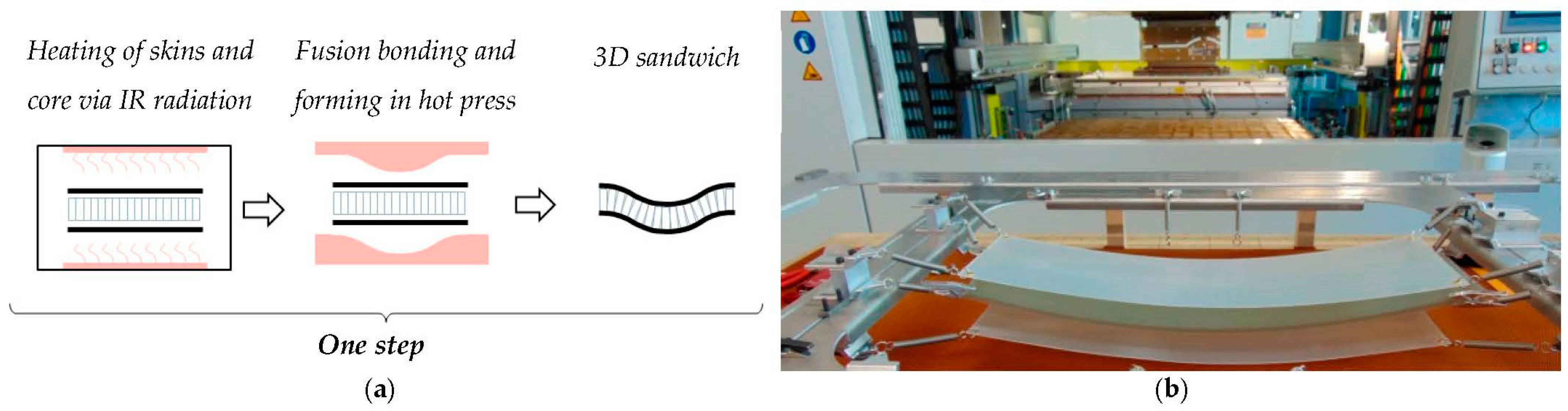
Figure 3.
Wrinkling due to shearing in textile reinforcement [25].
Figure 3.
Wrinkling due to shearing in textile reinforcement [25].

Figure 4.
The specimen under bias extension test before (a) and after (b) loading [17].
Figure 4.
The specimen under bias extension test before (a) and after (b) loading [17].
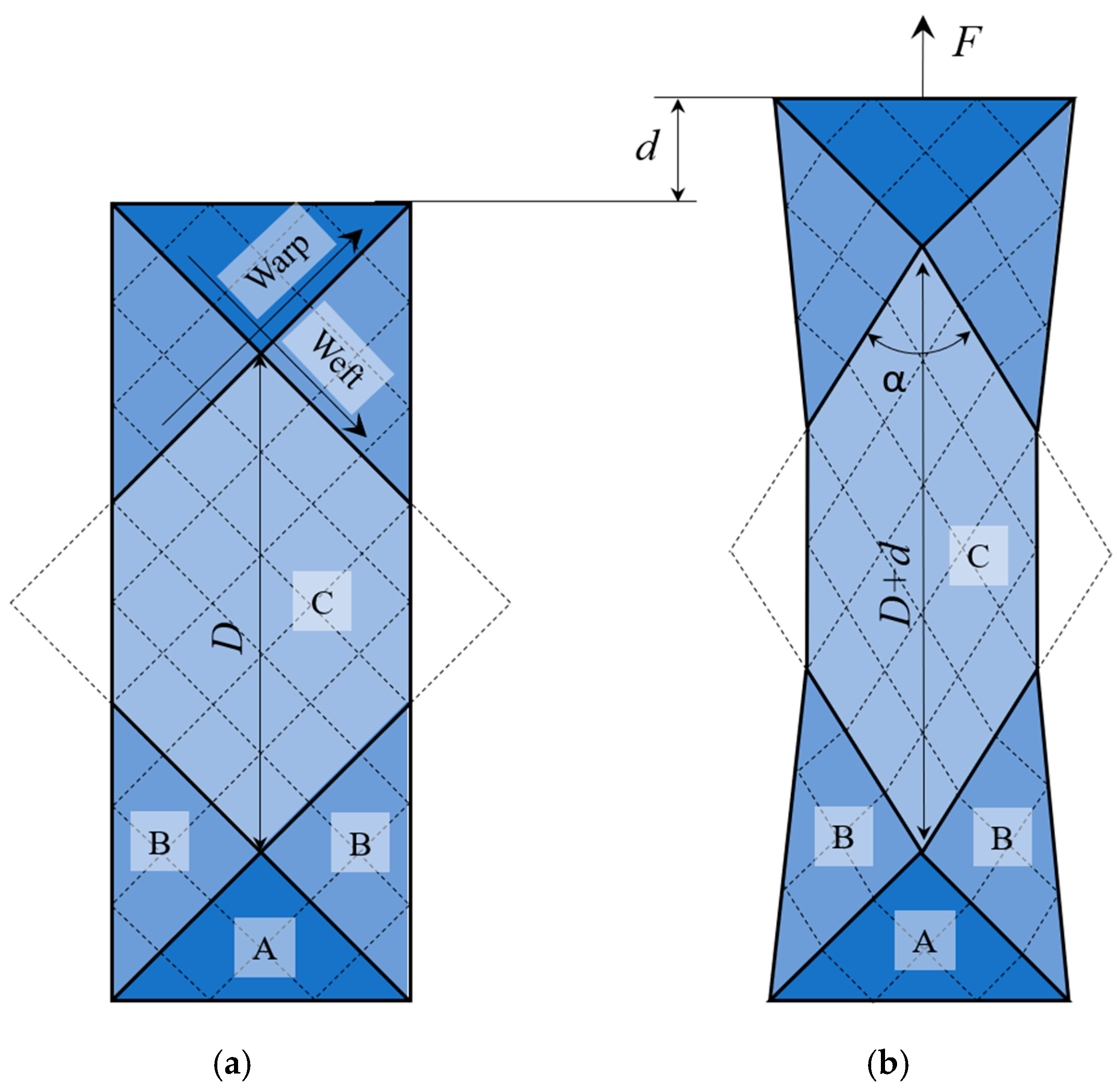
Figure 5.
A specimen in an environmental chamber before (a) and after (b) the bias extension test.
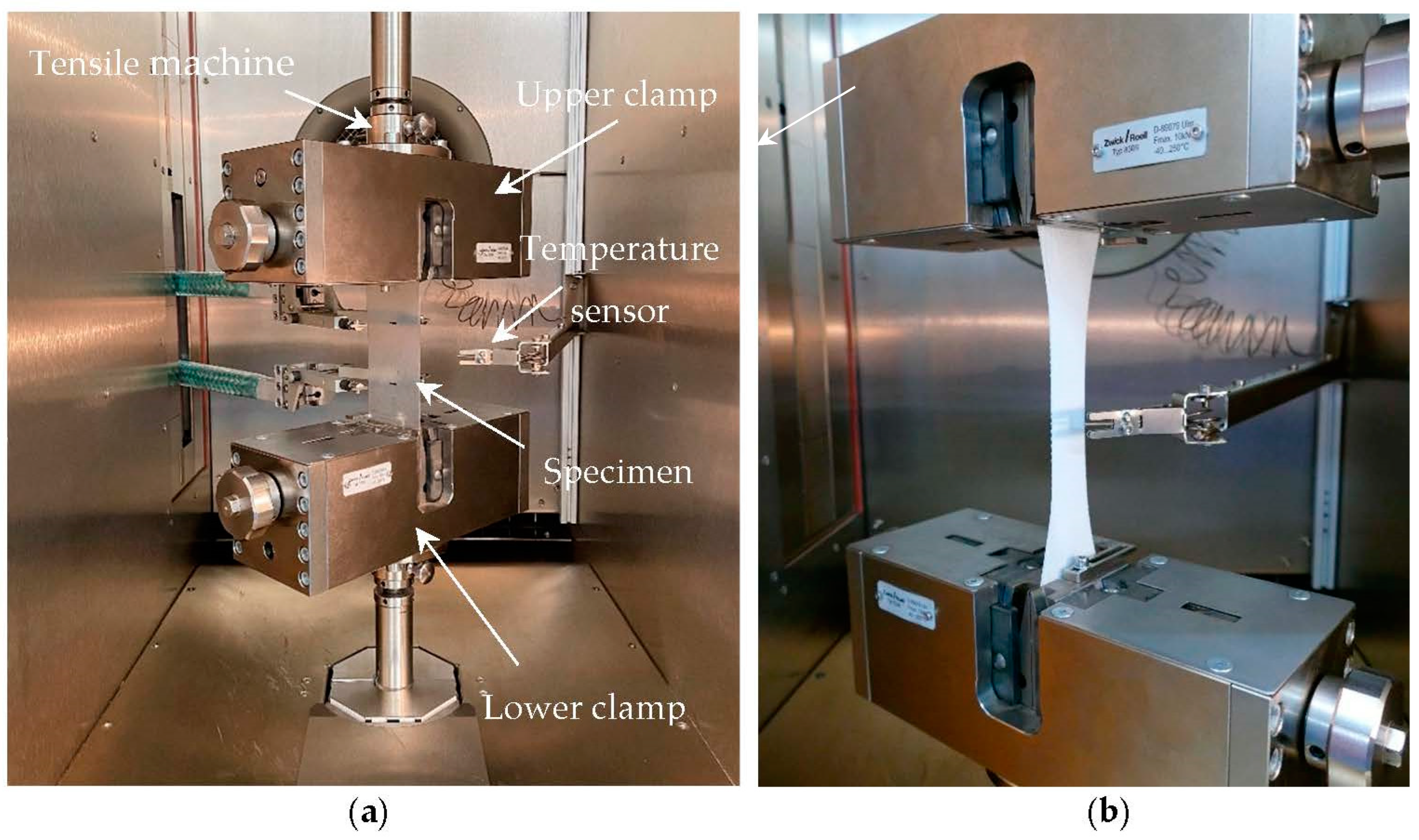
Figure 6.
Thermoforming model.
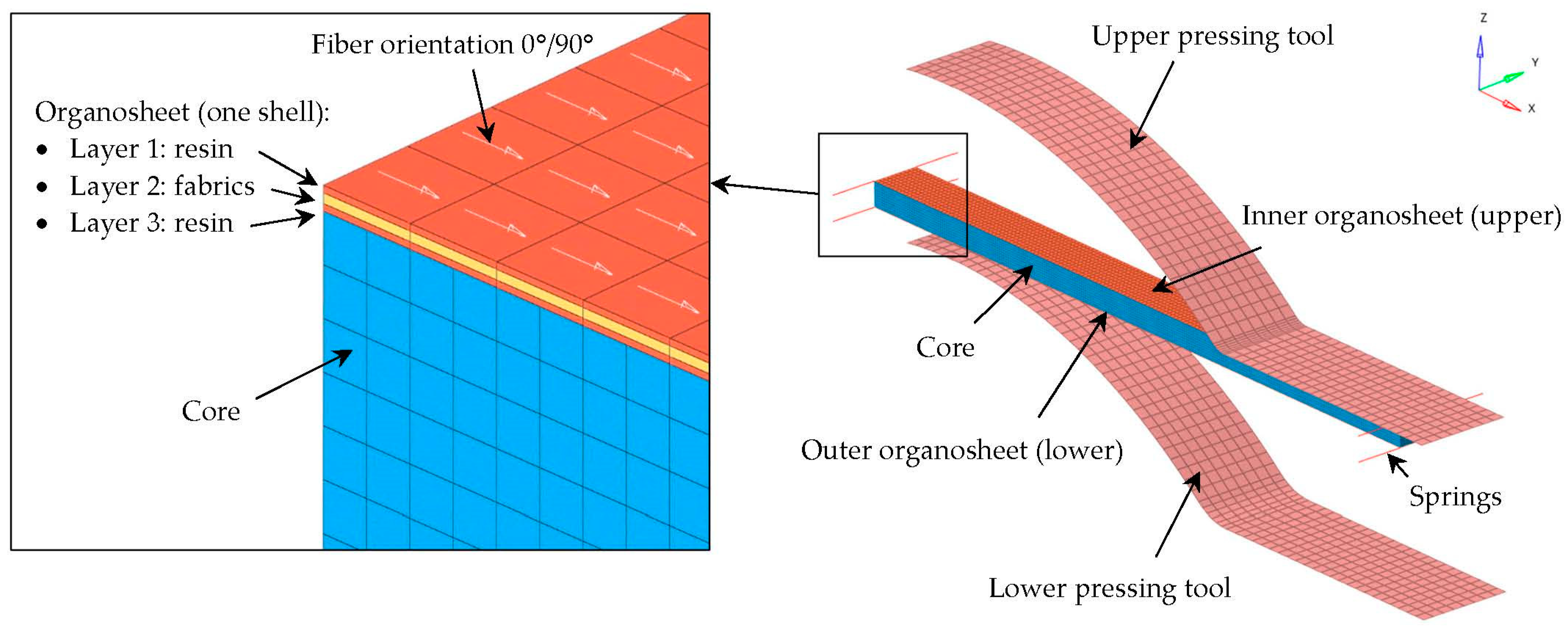
Figure 7.
Polycarbonate yield behavior for material law 73 (skin matrix) and law 74 (core) [36].
Figure 7.
Polycarbonate yield behavior for material law 73 (skin matrix) and law 74 (core) [36].

Figure 8.
Typical tensile stress–strain curve for material law 58 [35].
Figure 8.
Typical tensile stress–strain curve for material law 58 [35].

Figure 9.
Polycarbonate’s stress–strain curve from tensile test.

Figure 10.
Shear angle distribution at a displacement of 43 mm at 160 °C (a), 190 °C (b), and 220 °C (c).
Figure 10.
Shear angle distribution at a displacement of 43 mm at 160 °C (a), 190 °C (b), and 220 °C (c).
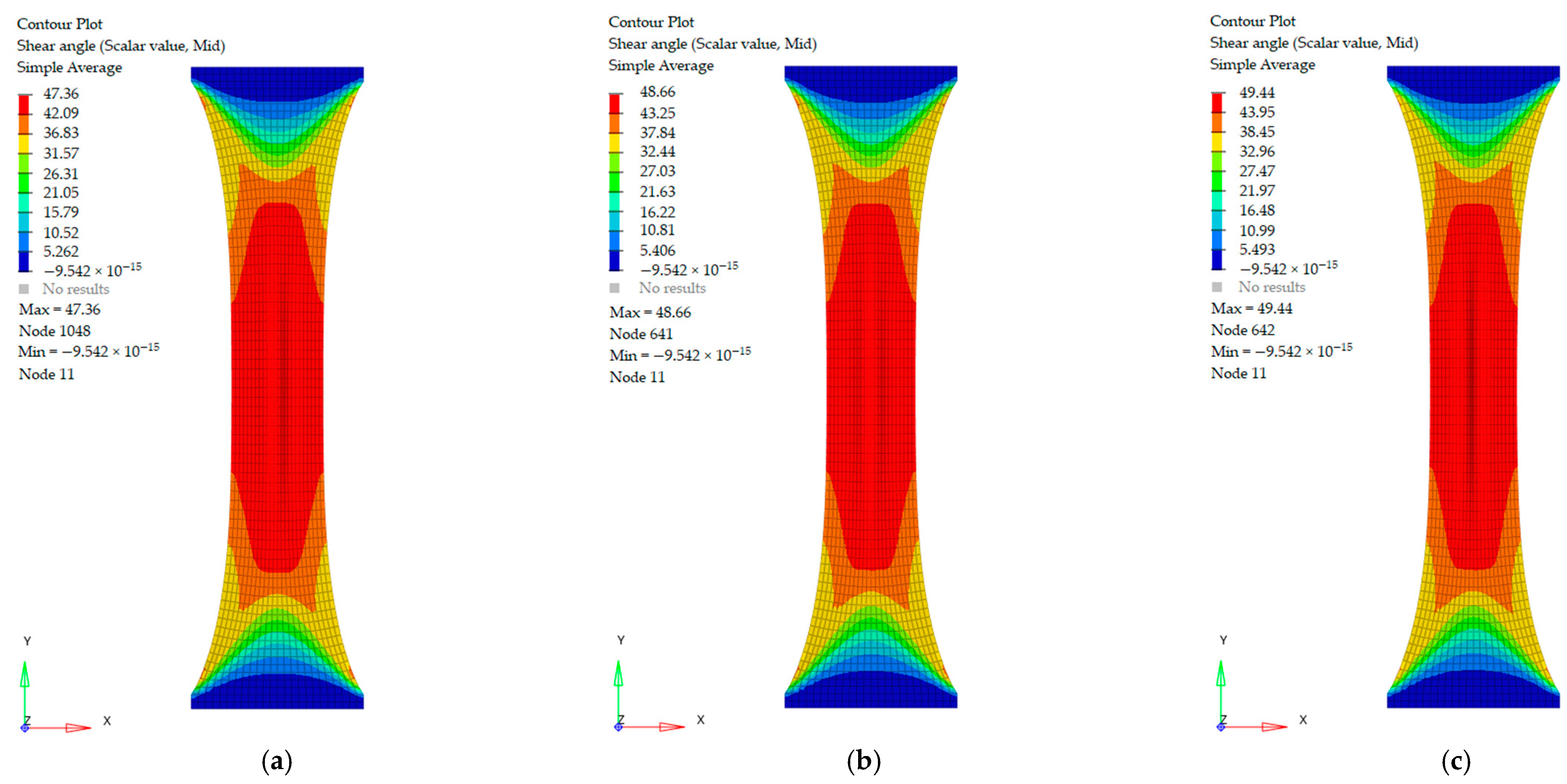
Figure 11.
Bias extension results of PC glass fiber organosheets at different temperatures.

Figure 12.
Comparison of the experimental (a) and simulation (b) results after shear deformation.
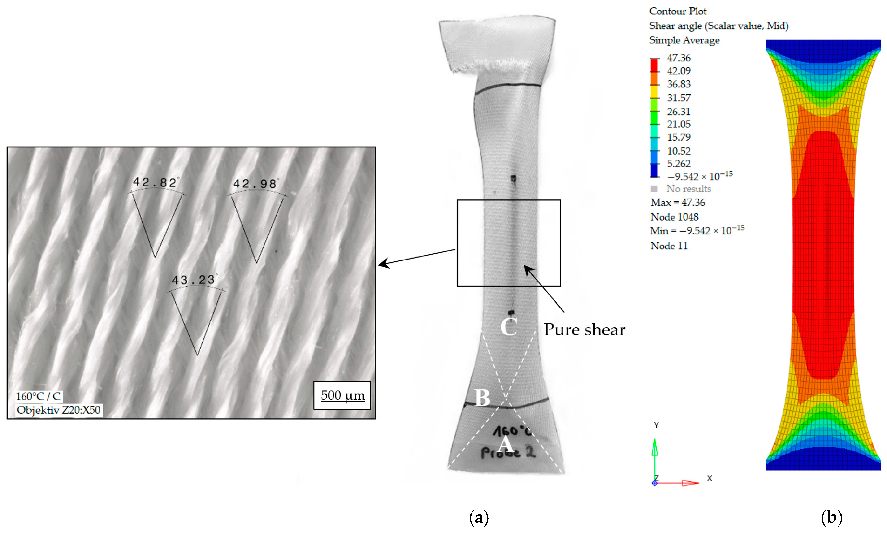
Figure 13.
Theoretical, numerical, and measured shear angle during a bias extension test.

Figure 14.
Sandwich panels produced with a pressing tool heated up to 190 °C (a) and 135 °C (b).
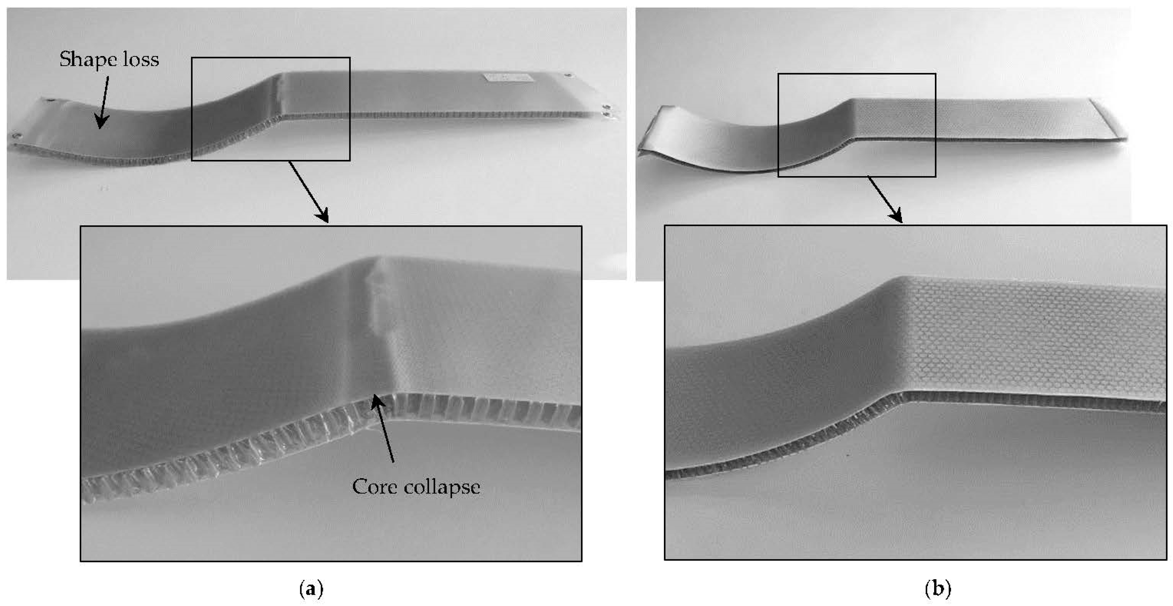
Figure 15.
Temperature distribution in sandwich panels produced with a pressing tool heated up to 190 °C (a) and 135 °C (b).
Figure 15.
Temperature distribution in sandwich panels produced with a pressing tool heated up to 190 °C (a) and 135 °C (b).

Figure 16.
Temperature versus time plot at 190 °C (a) and 135 °C (b).
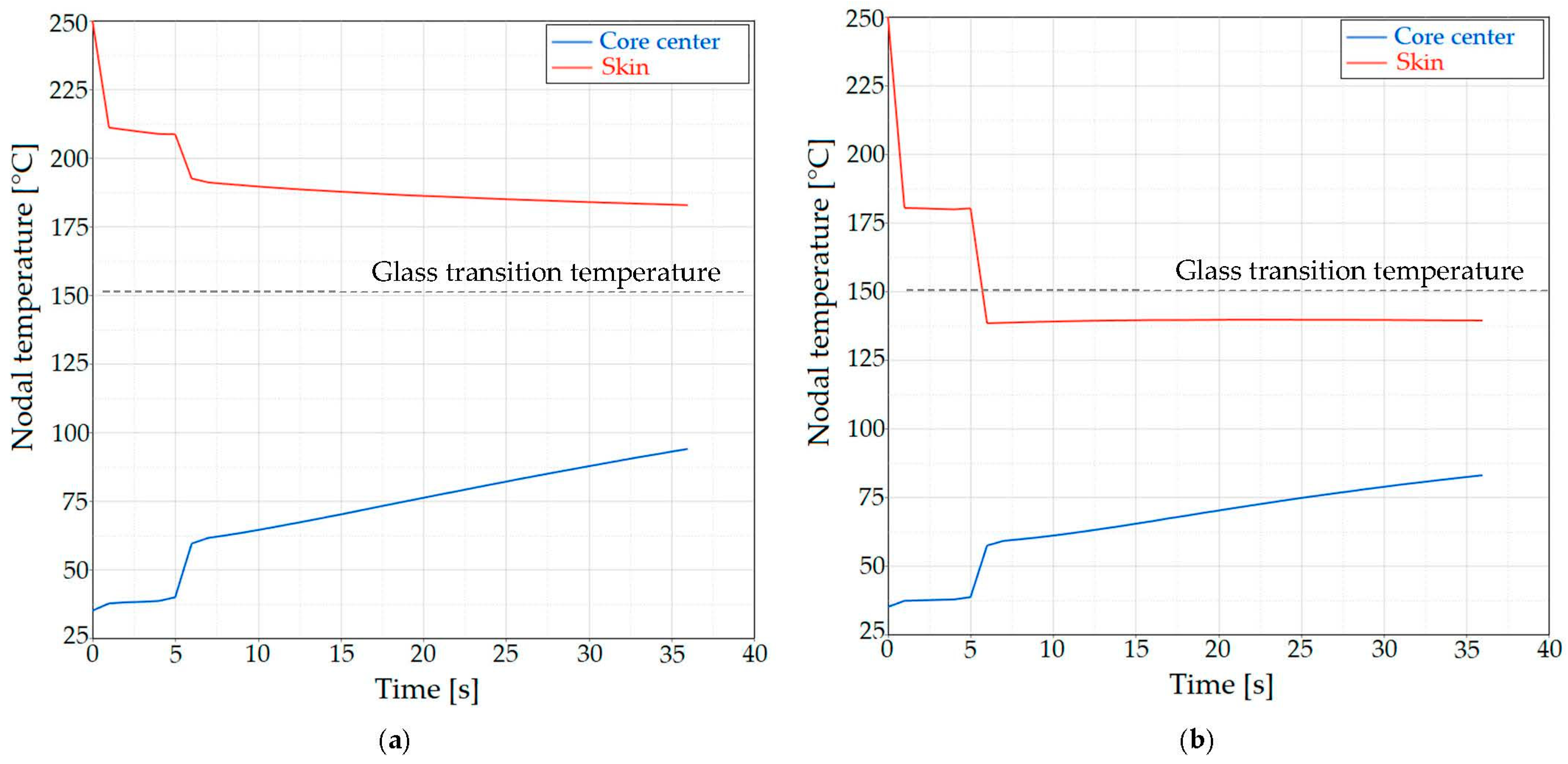
Figure 17.
Curved sandwich panels with fiber orientation of 0/90 (a) and ±45 degrees (b).
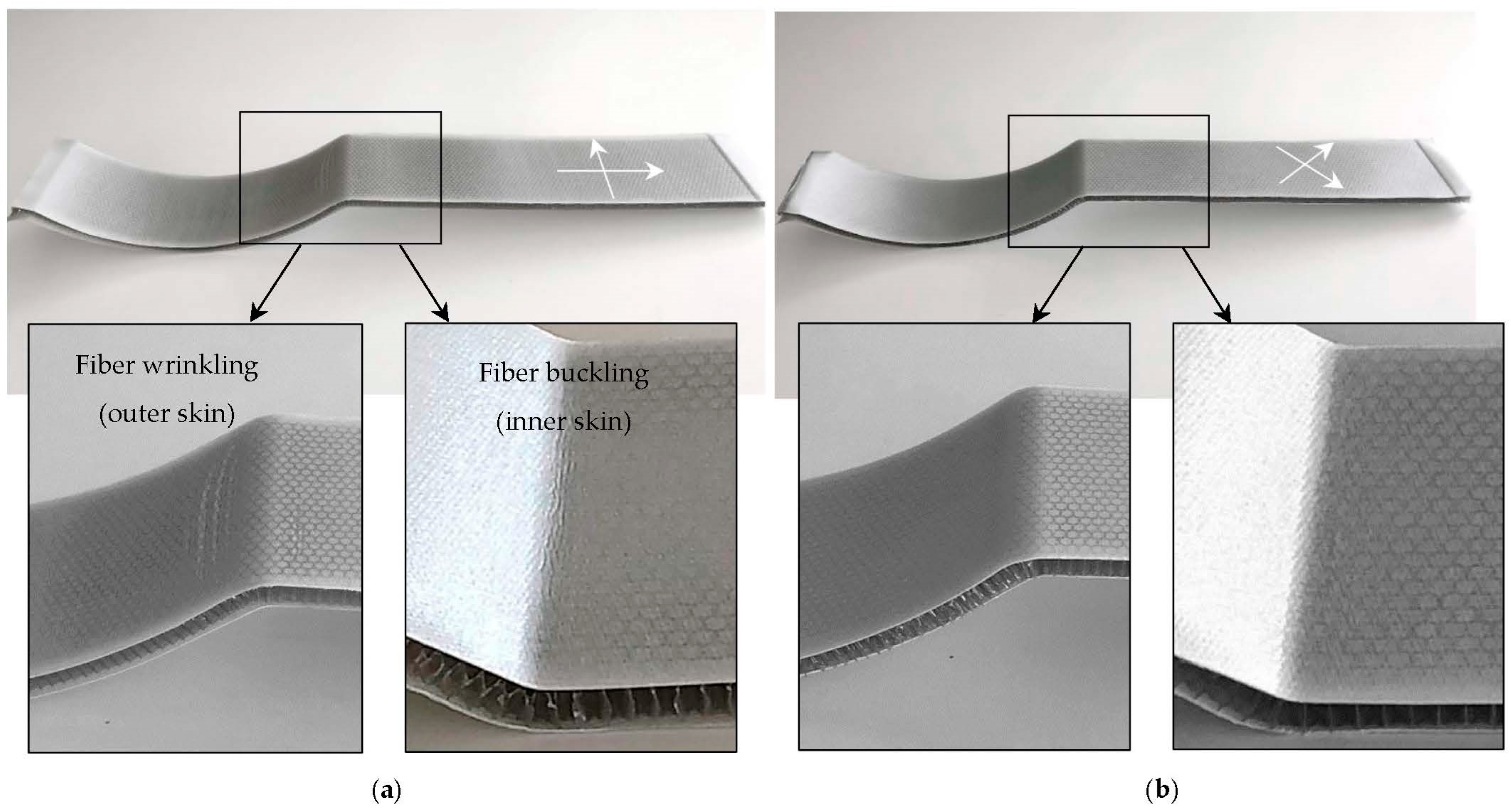
Figure 18.
Strain distribution in skins with fiber orientation of 0/90 (a) and ±45 degrees (b).

Figure 19.
Shear angle evolution in skins with fiber orientation 0/90 (a) and ±45 degrees (b).
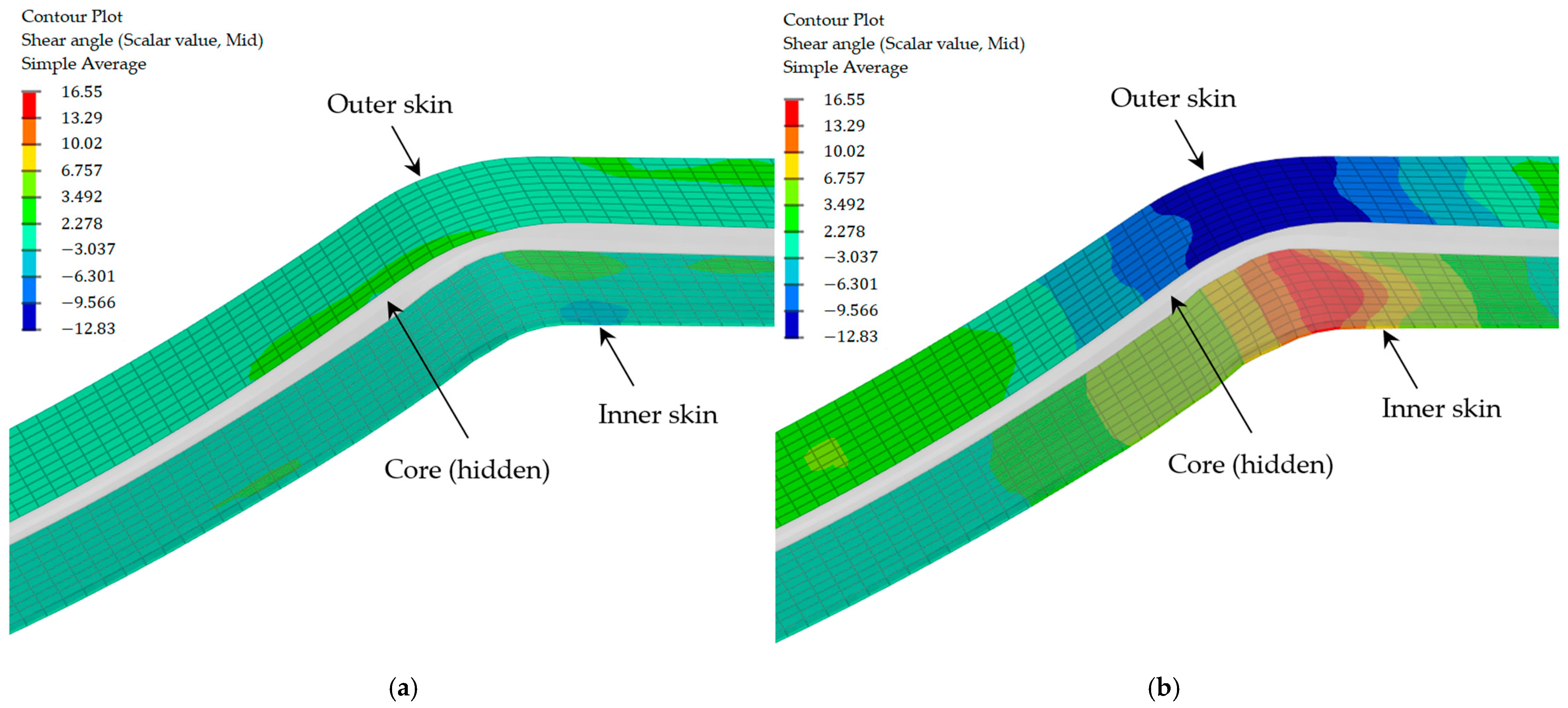
Figure 20.
Stress distribution in the sandwich structure during thermoforming.


Table 1.
Material properties for thermoforming analysis.
| Property | Polycarbonate (Skin Matrix Law 73 and Core Law 74) | Test Standard | Woven Fabric (Law 58) | Test Standard |
|---|---|---|---|---|
| Density (kg/m3) | 1330 | ISO 1183-1 [42] | 2600 | ISO 1183-1 [42] |
| Young modulus (MPa) | 2600 | ISO 527-2 [43] | - | - |
| Poisson ratio | 0.38 | ISO 527-2 [43] | - | - |
| Young modulus in warp direction (GPa) | - | - | 23.7 [23] | EN 2747-3 [48] |
| Young modulus in weft direction (GPa) | - | - | 24.1 [23] | EN 2747-3 [48] |
| Shear modulus (GPa) | - | - | 3.4 [23] | EN 6031 [49] |
| Thermal conductivity (W/m-°C) | 0.2 | ASTM E1461 [45] | 0.24 | ASTM C518 [46] |
| Specific heat capacity (J/kg-°C) | 1630 | ISO 11357-4 [44] | 810 | ISO 11357-4 [44] |
Disclaimer/Publisher’s Note: The statements, opinions and data contained in all publications are solely those of the individual author(s) and contributor(s) and not of MDPI and/or the editor(s). MDPI and/or the editor(s) disclaim responsibility for any injury to people or property resulting from any ideas, methods, instructions or products referred to in the content. |
© 2024 by the authors. Licensee MDPI, Basel, Switzerland. This article is an open access article distributed under the terms and conditions of the Creative Commons Attribution (CC BY) license (https://creativecommons.org/licenses/by/4.0/).
Share and Cite
MDPI and ACS Style
Latsuzbaya, T.; Middendorf, P.; Voelkle, D.; Weber, C. Thermomechanical Analysis of Thermoplastic Mono-Material Sandwich Structures with Honeycomb Core. J. Compos. Sci. 2024, 8, 18. https://doi.org/10.3390/jcs8010018
AMA Style
Latsuzbaya T, Middendorf P, Voelkle D, Weber C. Thermomechanical Analysis of Thermoplastic Mono-Material Sandwich Structures with Honeycomb Core. Journal of Composites Science. 2024; 8(1):18. https://doi.org/10.3390/jcs8010018
Chicago/Turabian StyleLatsuzbaya, Temuri, Peter Middendorf, Dietmar Voelkle, and Christoph Weber. 2024. "Thermomechanical Analysis of Thermoplastic Mono-Material Sandwich Structures with Honeycomb Core" Journal of Composites Science 8, no. 1: 18. https://doi.org/10.3390/jcs8010018