

Innovative Wedge Anchorage for CFRP Plates: Development and Testing

1
Department of Mechanical Engineering, King Faisal University, Al-Ahsa 31982, Saudi Arabia
2
Department of Mechanical & Mechatronics Engineering, University of Waterloo, Waterloo, ON N2L 3G1, Canada
3
Department of Civil and Environmental Engineering, University of Waterloo, Waterloo, ON N2L 3G1, Canada
*
Author to whom correspondence should be addressed.
J. Compos. Sci. 2024, 8(3), 103; https://doi.org/10.3390/jcs8030103
Submission received: 29 January 2024
/
Revised: 29 February 2024
/
Accepted: 7 March 2024
/
Published: 14 March 2024
(This article belongs to the Special Issue Carbon Fiber Composites, Volume III)
Abstract
:Gripping prestressed carbon fiber-reinforced polymers (CFRPs) in structural strengthening applications is challenging due to CFRPs’ susceptibility to lateral loading. This paper presents a reliable and reusable wedge anchorage for gripping CFRP plates that are 50 mm wide and 1.2 mm thick. The cylindrical anchorage, which is 75 mm long and 76.2 mm in diameter, consists of an external steel barrel, two internal steel wedges, and two soft copper sleeves. The barrel-wedge interface is designed using an innovative arc–linear configuration, through which the desired stress distribution is attained, preventing stress concentration and the premature failure of the CFRP plate. The wedge anchorage was experimentally tested by applying a displacement-controlled tensile load of 0.6 mm/min until the complete fracture of the CFRP plate. The anchorage’s performance was examined under distinct installation conditions by applying different presetting levels: high (40–120 kN) and low (hammering) presetting. It was observed that the anchorage successfully prevented CFRP premature failure in all tests by achieving an average tensile loading of 172.3 (±5.7) kN, exceeding its reported tensile strength of 168 kN (2800 MPa). Minor CFRP displacements of 6.26 (±0.75) mm and 3.33 (±0.16) mm were recorded under low and high presetting levels, respectively. Similarly, the CFRP slippage relative to the wedges for the low and high presetting tests was only 1.18 (±0.75) mm and 0.33 (±0.15) mm, respectively. Also, only minor scratches were observed in the wedge–barrel interface, indicating the absence of extensive plastic deformation.
1. Introduction
Numerous concrete structures require strengthening and repair due to the growing applied loads and reinforcement corrosion [1,2]. According to the American Society of Civil Engineering (ASCE) report (2017), infrastructure repair is anticipated to cost the United States about USD 2 trillion by 2025 [3]. The total replacement of the degraded concrete structures is not practical due to the associated costs and time; hence, the efficient strengthening of concrete structures with durable and corrosion-resistant retrofitting materials, such as carbon fiber-reinforced polymers (CFRPs), is essential. In addition to its high corrosion resistance, CFRPs have lightweight, superior tensile strength and exceptional fatigue properties, making them an excellent material for retrofitting concrete structures [4,5].
The overall performance of concrete structures can be enhanced by mounting CFRPs to its surface through adhesive bonding [6] or mechanical linkage [7]. While adhesive bonding is easy to apply, it is prone to CFRP delamination, particularly in hot environments [8]. On the other hand, properly designed mechanical linkages, such as anchorages, can effectively grip CFRP reinforcement, preventing delamination [9]. As reported by Al-Mahaidi and Kalfat (2010), using FRP anchorages increased the bond strength between FRP and concrete from about 5 MPa to 11.3 MPa, improving the delamination resistance and enabling higher prestressing levels [10]. Also, utilizing the high tensile strength of CFRP through prestressing can enhance the load-carrying capacity of concrete structures [11,12,13,14]. Hong and Park (2017) observed that increasing CFRPs’ prestressing level from 20% to 60% improved the flexural concrete-cracking load from 33.5 kN to 54.1 kN [11]. Similarly, Peng et al. (2016) reported that subjecting the CFRP reinforcement to pre-tension stress of 1000 MPa increased the concrete-cracking load from 18 kN to 60 kN [14]. However, prestressing CFRPs without causing premature failure is challenging due to their vulnerability to lateral loads [15,16,17]. Thus, several anchorage systems have been developed to grip CFRP elements effectively, including resin-potted [18,19,20,21,22], clamp [23,24], and wedge anchorages [25,26,27].
Resin-potted anchorage is a bond-based system consisting mainly of a steel sleeve and a resin that is made of an adhesive material or an expansive cement [18,19]. Zhang and Benmokrane (2004) reported that resin-potted anchorage can effectively grip CFRP elements without causing premature failure when a bonding anchorage length of 250 mm is provided [21]. Nonetheless, an adequate bond length is needed to reach CFRPs’ full strength without experiencing bond failure. As observed by Puigvert et al. (2014), increasing the bond length from 200 mm to 460 mm enhanced the tensile failure load from 58.7 kN to 110.7 kN [22]. In addition to its bond length requirement, an adequate curing time must be provided to attain its full gripping strength [28].
The clamp anchorage is another system utilized for gripping CFRP plates. It is generally composed of two steel clamps and a number of bolts. As reported by Bengar and Shahmansouri (2020), gripping CFRP plates using clamp anchorages instead of adhesive bonding improved the flexural strength of concrete, increasing its failure load from 206 kN to 255.3 kN [29]. Unlike the resin-potted anchorage, the clamp anchorage is a friction-based system that requires no curing time, making the installation process much faster. However, the clamp anchorage normally produces a uniform CFRP confinement (i.e., lateral stress) due to the even fastening of its bolts, resulting in stress concentration and premature CFRP failure [30]. Although it is possible to fasten the bolts to different degrees to minimize the stress concentration, a precise and adequate clamping force is essential to maintain the performance of the anchorage.
Similarly, the wedge anchorage is a friction-based system made of an external steel barrel, internal wedges, and soft sleeves. The wedge anchorage can produce a variable (non-uniform) CFRP confinement through the interference between its barrel and wedges, preventing stress concentration and premature CFRP failure [31]. As reported by Al-Mayah et al. (2001) and Han et al. (2017), wedge anchorages can utilize CFRPs’ full tensile strength without causing premature CFRP failure [26]. Also, the onsite prestressing of CFRP reinforcements using wedge anchorages is relatively fast due to its self-seating mechanism. During the prestressing process, the CFRP plate is pre-tensioned using a hydraulic jack until the required prestressing level is attained, after which the wedge anchorage is assembled through hammering [32]. As the applied tensile load is gradually released, the CFRP plate drives the wedges further into the barrel, resulting in a firm CFRP grip through the anchorage’s self-seating mechanism with a slight prestress loss. In addition to being reliable for gripping CFRP reinforcement, the wedge anchorage is reusable, compact in size, and easy to install, making it an excellent candidate for further research.
Most currently developed wedge anchorages were designed to grip circular FRP tendons. Little attention has been paid to developing wedge anchorages for CFRP plates. Therefore, the main objective of this paper is to present an innovative, compact, and reusable wedge anchorage for CFRP plates. Also, the performance of the developed anchorage system was experimentally tested under different presenting levels to demonstrate its reliability, reusability, and cost-effectiveness in field applications.
2. Test Elements
2.1. CFRP Plate
Unidirectional CFRP plates that are 1000 mm long, 50 mm wide, and 1.2 mm thick were tested. The plate has a high tensile strength of 2800 MPa, an excellent tensile strength-to-weight ratio of 1867 kN·m/kg, and a shear strength of 100 MPa. However, it has low lateral tensile and compressive strengths of 62 MPa and 350 MPa, respectively, making it vulnerable to transverse stress.
2.2. Copper Sleeves
Two soft copper sleeves that are 75 mm long, 50 mm wide, and 0.81 mm thick were placed between the two wedges and the CFRP plate to maximize the actual contact area, improve gripping, minimize stress concentration, and prevent the premature failure of CFRP [30,33]. Soft copper sleeves have been proven to enhance CFRP gripping [34], attributed to their role in filling surface asperities, resulting in better gripping at the CFRP-sleeve and wedge-sleeve interfaces. Hence, the copper sleeves were heat-treated at a temperature of 500 °C for an hour and then air-cooled before testing. A new set of disposable copper sleeves was used in each test to maintain the anchorage’s performance, as the sleeves are expected to experience considerable plastic deformation. This, however, has little impact on the anchorage’s installation cost, given the availability of the sleeve material with the required dimensions at a low cost.
2.3. Wedge Anchorages
Two wedge anchorages were used, namely the developed and dead-end systems. Both anchorages are generally similar; however, the dead-end is larger in length and diameter than the developed anchorage. The developed wedge anchorage consists of two identical wedges and one barrel. The novelty of the developed wedge anchorage is its unique arc–linear interface between the barrel and the wedges. The new configuration comprises two segments: an arc segment near the loading end (Edge 1) and a linear segment close to the presetting end (Edge 2), as illustrated in Figure 1. The arc segment of the interface is used to gradually increase the interference between the wedges and the barrel, creating a stronger grip of the CFRP plate. On the other hand, the linear segment is utilized to maintain the interference within the desired range to mitigate high stress and prevent plastic deformation of the elements. Also, it was observed through finite element (FE) modeling that using identical linear segments (e.g., identical slope) improved the anchorage performance [35]; thus, the wedges and the barrel were designed with identical linear segments.
The developed wedge anchorage is 70 mm in length and 76.2 in diameter. The radius for the arc-segment of 1750 mm was determined as appropriate for improving the performance after conducting an extensive numerical investigation using a verified finite element model [35]. Also, the linear segments of the wedges and the barrel were designed with identical linear segments with the same suitable slope that was determined using FE modeling. The best-performing dimensions of the developed anchorage are presented in Figure 1.
It is recommended to manufacture the anchorage from 440C stainless steel for field usage since it has high yield and tensile strengths and excellent corrosion resistance [36]. However, in this paper, the wedges and barrel were manufactured from heat-treated 4140 steel, which has comparable yield and tensile strengths of 1896 MPa and 1965 MPa, respectively. Also, the wedges and the barrel were made of the same material to minimize surface ploughing [37].
3. Test Procedures and Instrumentations
3.1. Part Assembly
The CFRP plate, the copper sleeves, the dead-end anchorage, and the developed wedge anchorage were carefully cleaned using acetone before assembly to remove any undesired particles, such as debris and lubrication from the previous test. The CFRP plate, sleeves, and wedges were carefully assembled and gripped using a C-clamp, as shown in Figure 2, before applying a high-pressure lubricant to the wedge-barrel interface to facilitate the movement of the core elements (CFRP plate, sleeves, and wedges) into the barrel. The wedges were then carefully hammered to insert the core elements into the barrel, as illustrated in Figure 3. It is worth noting that misassembling the elements, such as uneven insertion of the wedges, can alter the stress distribution within the CFRP plate and may affect anchorage performance. Thus, a digital vernier caliper was used to confirm the even placement of the wedges into the barrel.
3.2. Anchorage Presetting
After assembly, the wedges were pushed further into the barrel using two different presetting levels: high presetting using the hydraulic jack, shown in Figure 4, and low presetting by manual hammering. Two identical steel rods of the same dimensions were employed to evenly push the wedges into the barrel without damaging the CFRP plate, after which a digital vernier caliper was used to ensure even the presetting of the wedges.
Three presetting loads of 40 kN, 80 kN, and 120 kN were applied in the high presetting tests to investigate the presetting effect on the anchorage’s performance. The other three low-presetting tests were preset using manual hammering to examine the effectiveness of the anchorage’s self-seating mechanism.
3.3. CFRP Tensile Loading
The anchorage performance was examined by applying a slow uniaxial displacement-controlled tensile load of 0.6 mm/min to the CFRP plate until the CFRPs’ full fracture. The tensile load was applied using the rig, shown in Figure 5A, operated by a servo-hydraulic material testing system (MTS). The displacements of the wedges and the CFRP plate were measured using two linear variable differential transducers (LVDTs) mounted to the steel where the wedge anchorage was seated, as shown in Figure 5B. The tip of one LVDT was placed on the wedge to measure its displacement. The other LVDT was employed to measure the CFRPs’ displacement by positioning its probe tip on a metallic plate fixed to the CFRP plate. The CFRP slippage, which is the relative displacement of the CFRP plate with respect to the wedges, was determined by computing the difference between the readings of the two LVDTs, as shown in Figure 6.
4. Results and Discussion
4.1. General
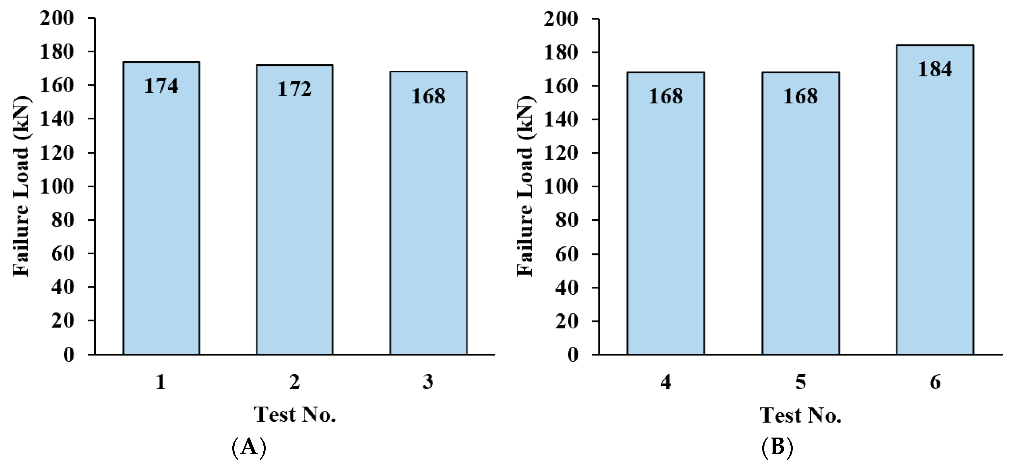
Six tensile tests were conducted under high and low presetting levels. Three tests were performed using high presetting levels of 40 kN, 80 kN, and 120 kN to examine the presetting effect on the anchorage’s performance. The other three tests were conducted with low presetting levels using manual hammering to investigate the effectiveness of the anchorage’s self-seating mechanism. A displacement-controlled tensile loading of 0.6 mm/min was applied until CFRP failure. The CFRPs’ fracture mode, shown in Figure 7, was observed in all tests outside the anchorage, indicating effective CFRP gripping. This was achieved by eliminating stress concentration and extensive CFRP plate slippage. The anchorage’s high performance was illustrated by the average recorded CFRP failure load of 172.3 (±5.7) kN, which surpassed the reported CFRP tensile strength of 168 kN (2800 MPa). As a comparison, the mechanical anchorage developed by Ye et al. (2018) successfully gripped a CFRP plate that was 25 mm wide and 1.5 mm thick with a tensile strength of 1950 MPa; however, the anchorage was somewhat large in size with a length of 150 mm, a width of 120 mm, and a thickness of 40 mm [24]. On the other hand, the developed wedge anchorage has a length of 70 mm and a diameter of 76.2 mm, and it was capable of gripping a wider CFRP plate with a higher tensile strength of 2800 MPa, illustrating its high performance despite its small size.
As stated earlier, the disposable soft copper sleeves were expected to experience substantial plastic deformation, as shown in Figure 8; hence, new sets of sleeves were used per test to maintain the anchorage’s performance. It is worth mentioning that the soft copper sleeves were 5 mm longer than the wedges for easier assembly. However, that extra length was not subjected to wedge confinement, which resulted in deformation at the sleeves’ ends.
The effect of the presetting level on the anchorage’s performance was assessed. It was observed that the presetting level had a minor effect on the CFRPs’ failure load, as indicated by the average fracture loads of 171.3 (±2.5) kN and 173.3 (±7.5) kN under high and low presetting levels, respectively. On the other hand, the CFRP displacement and slippage were substantially impacted by the presetting level. It was observed that the average CFRP displacement and slippage under low presetting were 6.04 (±0.27) mm and 1.18 (±0.75) mm, whereas the CFRP displacement and slippage were only 3.57 (±0.66) mm and 0.34 (±0.15) mm, respectively, in the case of high presetting. In other words, applying high presetting resulted in 41% and 71% reductions in the CFPR displacement and slippage, respectively. Based on these results, the wedge anchorage demonstrated an excellent performance under both low and high presetting levels.
The fracture mode of the CFRP plate was inspected, and the plastic deformation within the wedges and barrel was investigated after conducting the six tensile tests. It was observed that while the CFRP’s loaded end (Edge 1) fragmented, its anchored segment was still intact, illustrating the effective gripping of the anchorage. Also, it was found that the wedges and barrel experienced only minor plastic deformation, mainly at the loading (Edge 1) and presetting (Edge 2) ends, indicating that the anchorage can withstand further testing.
4.2. CFRP Failure Load
The performance of the wedge anchorage was investigated by analyzing the fracture load of the CFRP plate under high and low presetting levels. The recorded CFRP failure loads of the high presetting tests 1–3 are 174 kN, 172 kN, and 168 kN, respectively, with an average of 171.3 (±2.5) kN, which exceeded the reported CFRP tensile strength of 168 kN (2800 MPa), as illustrated in Figure 9A. It is noteworthy that applying a higher presetting level was not required to reach the CFRPs’ tensile strength. In fact, increasing the presetting load slightly reduced the CFRPs’ failure load. Increasing the presetting load from 40 kN (Test 1) to 120 kN (Test 3) decreased the CFRP failure load by 6 kN, attributed to the CFRPs’ preloading damage caused by excessive confinement.
On the other hand, the fracture loads of the low presetting tests 4–6 are 168 kN, 168 kN, and 184 kN, respectively, with an average of 173.3 (±7.5) kN, as shown in Figure 9B. Based on the results, the wedge anchorage successfully achieved the full reported tensile strength of the CFRP plates in all tests under both high and low presetting conditions, illustrating its excellent performance.
4.3. CFRP Displacement
The excessive displacement of the CFRP plate during the tensioning process is not desired in field applications since it causes a considerable loss of CFRP prestressing. Thus, the wedge anchorage was evaluated based on the resulting CFRP displacement, as shown in Figure 10. The general plot of the recorded load–displacement data consisted of vertical and inclined linear segments, which correlated well with previously reported findings [39]. It was observed that applying a higher presetting load produced a higher displacement-initiation load, represented by the vertical segment, and a lower CFRP displacement, attributed to the increased confinement. The presetting level had a minor effect on the resistance of wedge insertion into the barrel, represented by the inclined segment’s slope because it is primarily a function of the barrel’s thickness and the interference of the wedge–barrel interface. In other words, the presetting level had a significant impact on the CFRP displacement.
As illustrated in Figure 10A, increasing the presetting load from 40 kN (Test 1) to 120 kN (Test 3) reduced the CFRPs’ displacement, at a tensile load of 168 kN, from 3.91 mm to 2.65 mm, improving the prestressing effectiveness. Consequently, applying low presetting through manual hammering produced higher CFRP displacement with an average of 6.04 (±0.27) mm, as shown in Figure 10B. However, it is clear from the results that the wedge anchorage allowed only minor CFRP displacement ranging from 2.65 mm to 6.35 mm, demonstrating its ability to preserve the CFRP prestressing. It is worth noting that the CFRP plate of Test 4 experienced noticeable displacement as the tensile loading was increased from 15 kN to 38 kN, possibly due to the uneven hammering of the two wedges. Nonetheless, the wedge anchorage was still capable of gripping the CFRP plate effectively.
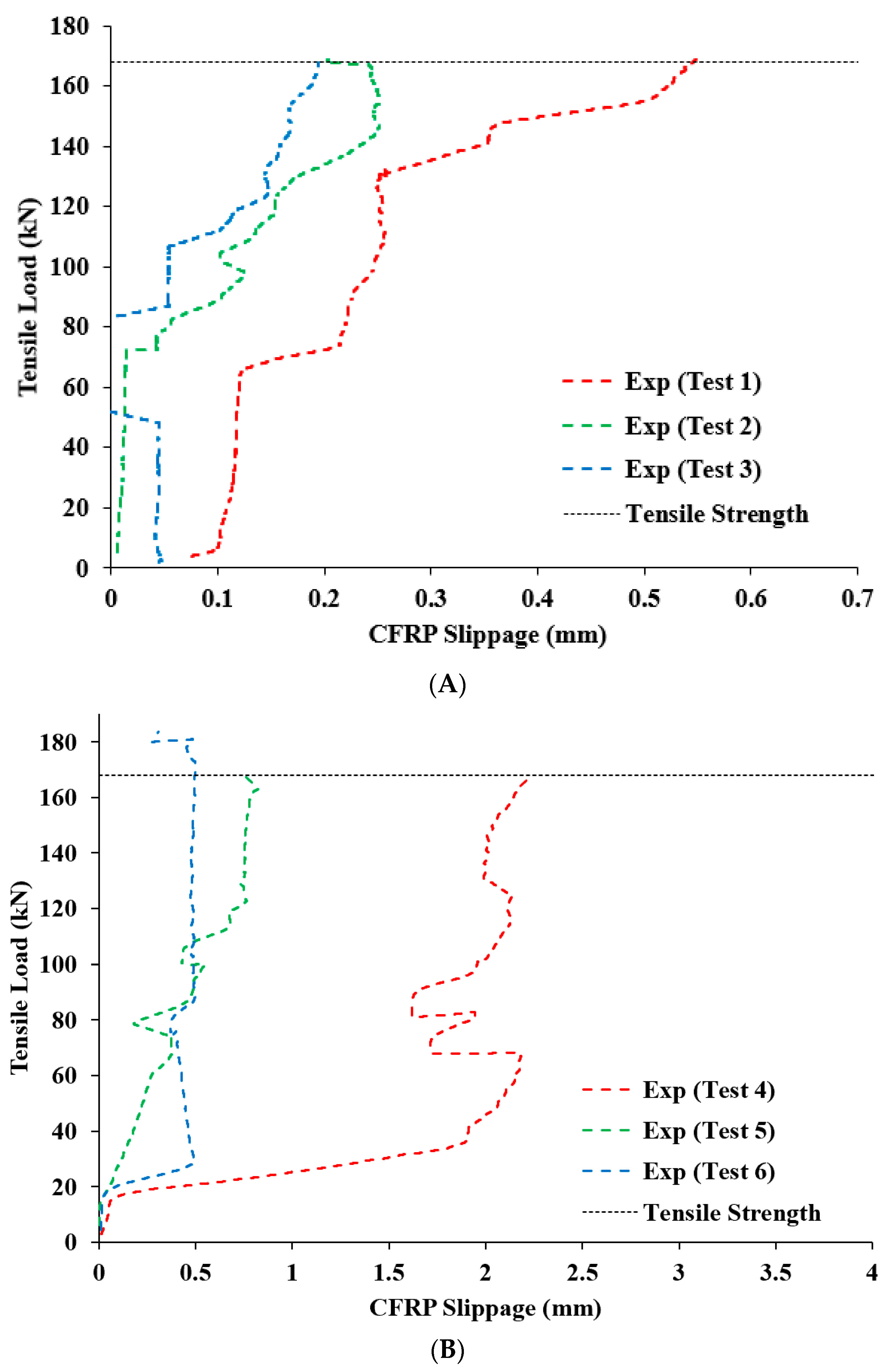
4.4. CFRP Slippage
Investigating the CFRP slippage, which is the displacement with respect to the wedges, is crucial since CFRP is vulnerable to abrasion damage that can lead to premature fracture. Therefore, the CFRP slippage was recorded and analyzed, as illustrated in Figure 11. It was observed that the maximum recorded CFRP slippages of the high presetting tests 1–3 were 0.55 mm, 0.25 mm, and 0.2 mm, respectively, with an average of 0.33 (±0.15) mm. Increasing the presetting level generally decreased the CFRP slippage. Hence, increasing the presetting load from 40 kN (Test 1) to 80 kN (Test 2) and 120 kN (Test 3) reduced the CFRP slippage by 55% and 64%, respectively.
As a result, higher CFRP slippage occurred in the low presetting tests. The maximum recorded CFRP slippage of the low presetting tests 4–6 was 2.2 mm, 0.82 mm, and 0.5 mm, respectively, with an average of 1.18 (±0.75) mm. The CFRP plate of Test 4 experienced almost 85% of its slippage as the tensile loading was increased from 15 kN to 38 kN, likely because of uneven presetting of the wedges. On the contrary, the CFRP slippage of Test 6 was only 0.5 mm despite being manually hammered, illustrating the anchorage’s excellent performance even under low presetting. Based on the results, the wedge anchorage minimized the CFRP displacement with respect to the wedges and, consequently, mitigated the abrasion damage, preventing the premature failure of the CFRP plate.
4.5. CFRP Fracture and Anchorage Damage Analysis
A fragmented CFRP plate failure, shown in Figure 12, was observed after reaching the ultimate load in every test. As illustrated, while the CFRPs’ loaded end experienced full rupture, the anchored segment of the CFRPs remained intact. This is evidence that the wedge anchorage successfully gripped the CFRP plate and prevented fracture propagation into the anchored portion of the CFRP plate inside the anchorage. Advanced monitoring technologies (e.g., high-speed camera) can be employed to gain a better understanding of the CFRPs’ failure process.
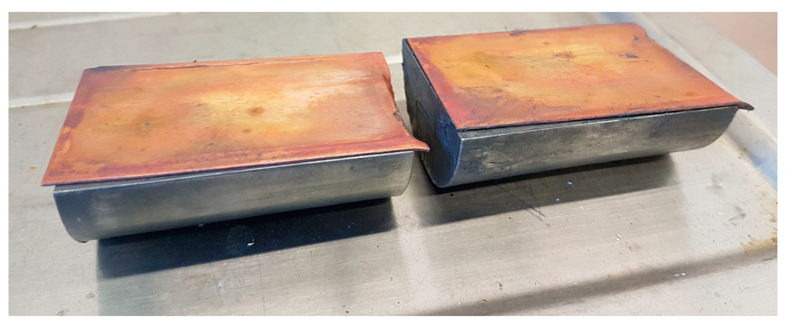
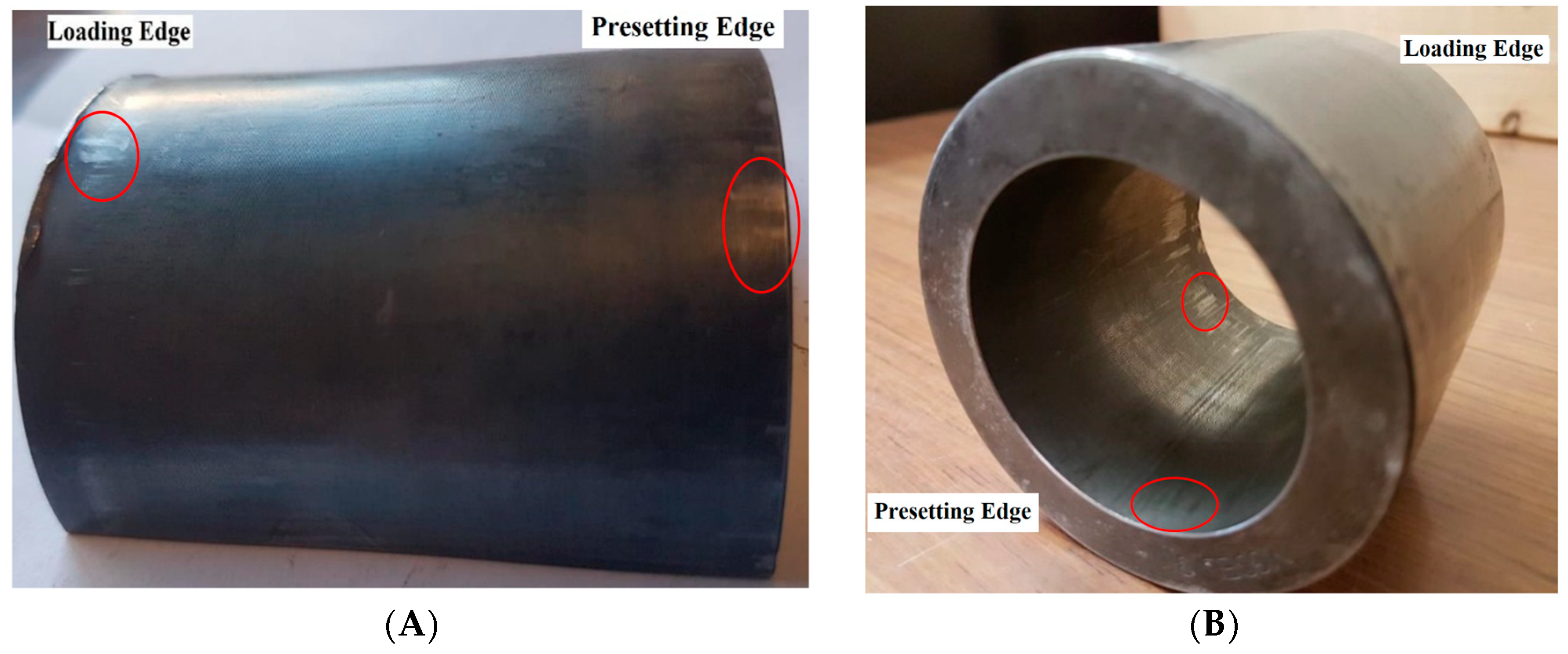
The wedge anchorage was visually inspected after conducting the tensile tests. Minor plastic deformation was observed mainly at the loading (Edge 1) and presetting (Edge 2) ends of the wedges and barrel, as highlighted in Figure 13. Different underlying factors were involved in producing plastic deformation at each edge. While plastic deformation near the loading end was mostly caused by elevated shear stress between the barrel and the wedges, plastic deformation around the presetting end was induced by a combination of high shear and contact (interference) stresses. The partial removal of lubrication at the loading end by the moving wedges and the low barrel thickness at the presetting end could have contributed to the plastic deformation within the anchorage. It is worth noting that the machining pattern on the surface is still visible, illustrating the absence of significant plastic deformation. Therefore, the anchorage maintained its excellent performance throughout the repeated tests, proving that its performance was not affected by the minor plastic deformation.
5. Conclusions
A compact, reliable, and reusable wedge anchorage for CFRP plates was developed using the innovative configuration that utilized an arc-linear profile in the wedge-barrel interface. The performance of the wedge anchorage was tested repeatedly under high and low presetting levels. The CFRP failure load, displacement, slippage, and fracture mode were analyzed. Based on the experimental results, the following points were concluded.
- The wedge anchorage effectively gripped the CFRP plate under both high and low presetting conditions until its full reported tensile strength was reached by preventing stress concentration within the CFRP plate.
- Only minor CFRP displacement ranging from 2.65 mm to 6.35 mm was recorded, indicating that the wedge anchorage is capable of preserving CFRP prestressing.
- The CFRP plate experienced low slippage of only 0.2–2.2 mm, mitigating abrasion damage.
- Applying a higher presetting level had a minor effect on the failure load of the CFRP plate, but it substantially reduced the CFRPs’ displacement and slippage.
- Post-experimental visual inspection revealed that the anchored segment of the CFRP plate remained intact even after the full fracture of its loading end.
- The wedge anchorage maintained its excellent performance throughout the repeated tests while enduring only minor surface scratches at the loading and presetting ends of its wedges and barrel.
Author Contributions
Conceptualization, M.A. and A.A.-M.; methodology, M.A. and A.A.-M.; validation, M.A. and A.A.-M.; formal analysis, M.A. and A.A.-M.; investigation, M.A. and A.A.-M.; writing—original draft preparation, M.A.; writing—review and editing, A.A.-M.; visualization, M.A. and A.A.-M.; supervision, A.A.-M., funding acquisition, M.A. All authors have read and agreed to the published version of the manuscript.
Funding
This work was supported by the Saudi Arabian Cultural Bureau (SACB), Ottawa, Canada. It was also supported by the Deanship of Scientific Research at King Faisal University.
Data Availability Statement
The research-related data is illustrated in the figures.
Conflicts of Interest
The authors declare no conflict of interest.
References
- Wardhana, K.; Hadipriono, F. Analysis of Recent Bridge Failures in the United States. J. Perform. Constr. Facil. 2003, 17, 144–150. [Google Scholar] [CrossRef]
- Petrović, Z.C. Catastrophes caused by corrosion. Vojnoteh. Glas. 2016, 64, 1048–1064. [Google Scholar] [CrossRef]
- ASCE Infrastructure Report Card; American Society of Civil Engineers (ASCE): Reston, VA, USA, 2017.
- Al-Mahaidi, R.; Kalfat, R. Investigation into CFRP plate end anchorage utilising uni-directional fabric wrap. Compos. Struct. 2011, 93, 821–830. [Google Scholar] [CrossRef]
- Meier, U. Carbon fiber-reinforced polymers: Modern materials in bridge engineering. Struct. Eng. Int. 1992, 2, 7–12. [Google Scholar] [CrossRef]
- Hassan, S.A.; Gholami, M.; Ismail, Y.S.; Sam, A.R.M. Characteristics of concrete/CFRP bonding system under natural tropical climate. Constr. Build. Mater. 2015, 77, 297–306. [Google Scholar] [CrossRef]
- Zheng, Y.; Zhou, Y.; Zhou, Y.; Pan, T.; Zhang, Q.; Liu, D. Cracking behavior of reinforced concrete beams strengthened with CFRP anchorage system under cyclic and monotonic loading. Eng. Struct. 2020, 207, 110222. [Google Scholar] [CrossRef]
- Al-Safy, R.; Al-Mahaidi, R.; Simon, G.P.; Habsuda, J. Experimental investigation on the thermal and mechanical properties of nanoclay-modified adhesives used for bonding CFRP to concrete substrates. Constr. Build. Mater. 2012, 28, 769–778. [Google Scholar] [CrossRef]
- Al-Rousan, R.Z. Impact of elevated temperature and anchored grooves on the shear behavior of reinforced concrete beams strengthened with CFRP composites. Case Stud. Constr. Mater. 2021, 14, e00487. [Google Scholar] [CrossRef]
- Kalfat, R.; Al-Mahaidi, R. Investigation into bond behaviour of a new CFRP anchorage system for concrete utilising a mechanically strengthened substrate. Compos. Struct. 2010, 92, 2738–2746. [Google Scholar] [CrossRef]
- Hong, S.; Park, S.-K. Concrete beams strengthened with prestressed unbonded carbon-fiber-reinforced polymer plates: An experimental study. Polym. Compos. 2017, 38, 2459–2471. [Google Scholar] [CrossRef]
- Hong, S.; Park, S.-K. Effect of prestress and transverse grooves on reinforced concrete beams prestressed with near-surface-mounted carbon fiber-reinforced polymer plates. Compos. Part B Eng. 2016, 91, 640–650. [Google Scholar] [CrossRef]
- Peng, H.; Zhang, J.; Cai, C.S.; Liu, Y. An experimental study on reinforced concrete beams strengthened with prestressed near surface mounted CFRP strips. Eng. Struct. 2014, 79, 222–233. [Google Scholar] [CrossRef]
- Peng, H.; Zhang, J.; Shang, S.; Liu, Y.; Cai, C.S. Experimental study of flexural fatigue performance of reinforced concrete beams strengthened with prestressed CFRP plates. Eng. Struct. 2016, 127, 62–72. [Google Scholar] [CrossRef]
- Benmokrane, B.; Xu, H.; Nishizaki, I. Aramid and carbon fibre-reinforced plastic prestressed ground anchors and their field applications. Can. J. Civ. Eng. 1997, 24, 968–985. [Google Scholar] [CrossRef]
- Kim, H.-J.; Sim, J. Mechanical properties of GFRP slip-form for in-situ application. KSCE J. Civ. Eng. 2016, 20, 1842–1851. [Google Scholar] [CrossRef]
- Zhao, X.-L. FRP-Strengthened Metallic Structures; CRC Press: Boca Raton, FL, USA, 2014; ISBN 978-0-203-89521-4. [Google Scholar]
- Lees, J.M.; Gruffydd-Jones, B.; Burgoyne, C.J. Expansive cement couplers: A means of pre-tensioning fibre-reinforced plastic tendons. Constr. Build. Mater. 1995, 9, 413–423. [Google Scholar] [CrossRef]
- Meier, U.; Farshad, M. Connecting high-performance carbon-fiber-reinforced polymer cables of suspension and cable-stayed bridges through the use of gradient materials. J. Comput.-Aided Mater. Des. 1996, 3, 379–384. [Google Scholar] [CrossRef]
- Taerwe, L. Non-Metallic (FRP) Reinforcement for Concrete Structures: Proceedings of the Second International RILEM Symposium; CRC Press: Boca Raton, FL, USA, 1995; ISBN 978-0-419-20540-1. [Google Scholar]
- Zhang, B.; Benmokrane, B. Design and evaluation of a new bond-type anchorage system for fiber reinforced polymer tendons. Can. J. Civ. Eng. 2004, 31, 14–26. [Google Scholar] [CrossRef]
- Puigvert, F.; Crocombe, A.D.; Gil, L. Static analysis of adhesively bonded anchorages for CFRP tendons. Constr. Build. Mater. 2014, 61, 206–215. [Google Scholar] [CrossRef]
- Schmidt, J.W.; Bennitz, A.; Taljsten, B.; Pedersen, H. Development of Mechanical Anchor for CFRP Tendons Using Integrated Sleeve. J. Compos. Constr. 2010, 14, 397–405. [Google Scholar] [CrossRef]
- Ye, H.; Liu, C.; Hou, S.; Wang, T.; Li, X. Design and experimental analysis of a novel wedge anchor for prestressed CFRP plates using pre-tensioned bolts. Compos. Struct. 2018, 206, 313–325. [Google Scholar] [CrossRef]
- Burtscher, S. Wedge Anchorage for CFRP Strips. J. Compos. Constr. 2008, 12, 446–453. [Google Scholar] [CrossRef]
- Han, Q.; Wang, L.; Xu, J. Test and numerical simulation of large angle wedge type of anchorage using transverse enhanced CFRP tendons for beam string structure. Constr. Build. Mater. 2017, 144, 225–237. [Google Scholar] [CrossRef]
- Sayed-Ahmed, E.Y.; Shrive, N.G. A new steel anchorage system for post-tensioning applications using carbon fibre reinforced plastic tendons. Can. J. Civ. Eng. 1998, 25, 113–127. [Google Scholar] [CrossRef]
- Czaderski, C.; Martinelli, E.; Michels, J.; Motavalli, M. Effect of curing conditions on strength development in an epoxy resin for structural strengthening. Compos. Part B 2011, 43, 398–410. [Google Scholar] [CrossRef]
- Akbarzadeh Bengar, H.; Shahmansouri, A.A. A new anchorage system for CFRP strips in externally strengthened RC continuous beams. J. Build. Eng. 2020, 30, 101230. [Google Scholar] [CrossRef]
- Schmidt, J.W.; Bennitz, A.; Täljsten, B.; Goltermann, P.; Pedersen, H. Mechanical anchorage of FRP tendons—A literature review. Constr. Build. Mater. 2012, 32, 110–121. [Google Scholar] [CrossRef]
- Al-Mayah, A.; Soudki, K.; Plumtree, A. Simplified Anchor System for CFRP Rods. J. Compos. Constr. 2013, 17, 584–590. [Google Scholar] [CrossRef]
- Li, X.; Deng, J.; Wang, Y.; Xie, Y.; Liu, T.; Rashid, K. RC beams strengthened by prestressed CFRP plate subjected to sustained loading and continuous wetting condition: Time-dependent prestress loss. Constr. Build. Mater. 2021, 275, 122187. [Google Scholar] [CrossRef]
- Feng, P.; Zhang, P.; Meng, X.; Ye, L. Mechanical Analysis of Stress Distribution in a Carbon Fiber-Reinforced Polymer Rod Bonding Anchor. Polymers 2014, 6, 1129–1143. [Google Scholar] [CrossRef]
- Al-Mayah, A.; Soudki, K.; Plumtree, A. Effect of sleeve material on interfacial contact behavior of CFRP-metal couples. J. Mater. Civ. Eng. 2006, 18, 825–830. [Google Scholar] [CrossRef]
- Alhusain, M. Development, Optimization and Testing of an Innovative Wedge Anchorage for CFRP Plates. Master’s Thesis, University of Waterloo, Waterloo, ON, Canada, 2018. [Google Scholar]
- American Iron and Steel Institute. Design Guidelines for the Selection and Use of Stainless Steel; American Iron and Steel Institute: Washington, DC, USA, 1993. [Google Scholar]
- Shaji, S.; Radhakrishnan, V. An investigation on solid lubricant moulded grinding wheels. Int. J. Mach. Tools Manuf. 2003, 43, 965–972. [Google Scholar] [CrossRef]
- Alhusain, M.; Al-Mayah, A. Novel Wedge Anchorage for CFRP Plates. In Proceedings of the 10th International Conference on FRP Composites in Civil Engineering, İstanbul, Turkey, 8–10 December 2021; Ilki, A., Ispir, M., Inci, P., Eds.; Springer International Publishing: Cham, Switzerland, 2022; pp. 2197–2208. [Google Scholar]
- Al-Mayah, A.; Soudki, K.; Plumtree, A. Experimental and analytical investigation of a stainless steel anchorage for CFRP prestressing tendons. PCI J. 2001, 46, 88–99. [Google Scholar] [CrossRef]
Figure 1.
Dimensions of the anchorage’s (A) wedges and (B) barrel in mm.

Figure 2.
Assembled CFRP plate, sleeves, and wedges before lubrication.
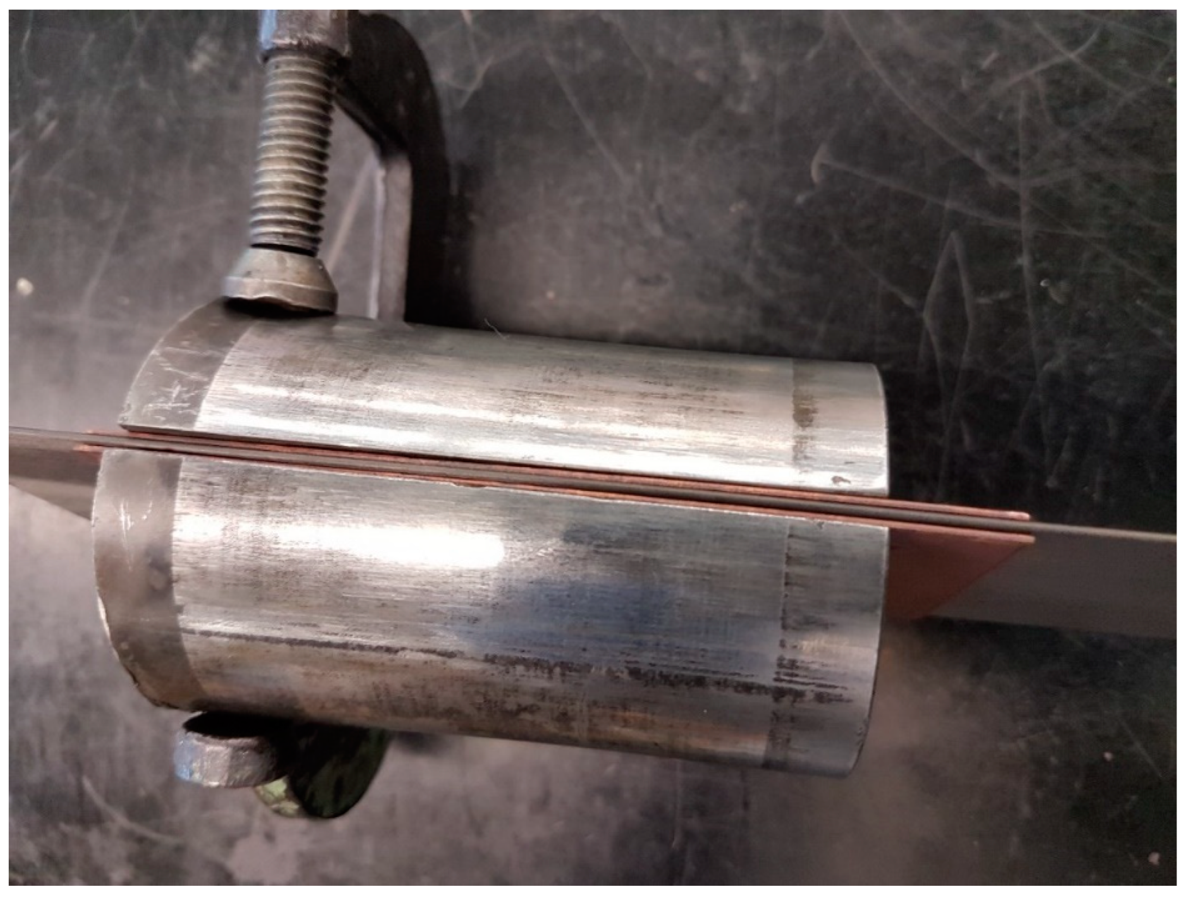
Figure 3.
Assembled wedge anchorage (left), dead-end anchorage (right), and CFRP plate.
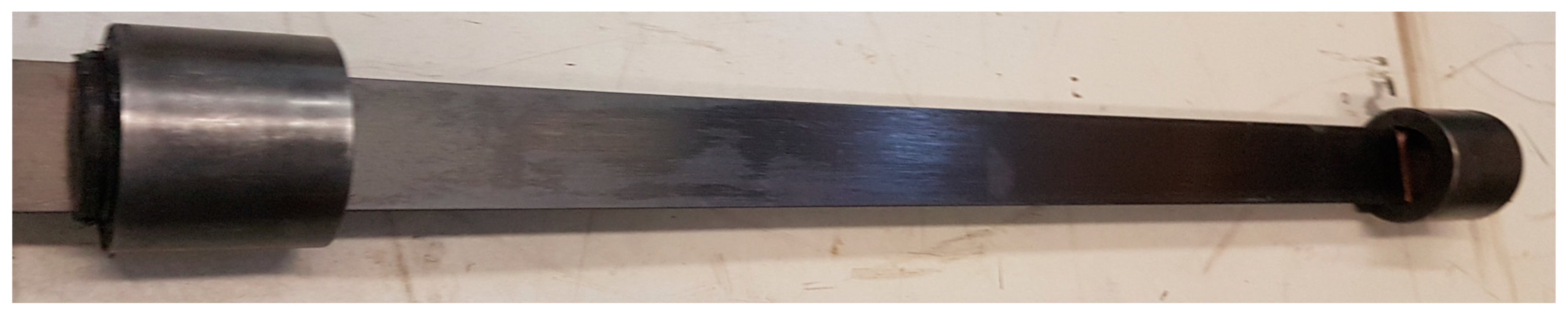
Figure 4.
Anchorage presetting: (A) hydraulic press apparatus and (B) presetting setup. Reproduced from Alhusain and Al-Mayah (2022) [38] with permission from Springer Nature.
Figure 4.
Anchorage presetting: (A) hydraulic press apparatus and (B) presetting setup. Reproduced from Alhusain and Al-Mayah (2022) [38] with permission from Springer Nature.

Figure 5.
Tensile loading: (A) test rig with assembled CFRP plate, two anchorages, and two LVDTs and (B) the setup of two LVDTs. Reproduced from Alhusain and Al-Mayah (2022) [38] with permission from Springer Nature.
Figure 5.
Tensile loading: (A) test rig with assembled CFRP plate, two anchorages, and two LVDTs and (B) the setup of two LVDTs. Reproduced from Alhusain and Al-Mayah (2022) [38] with permission from Springer Nature.

Figure 6.
Recorded wedge, CFRP displacements, and CFRP slippage.
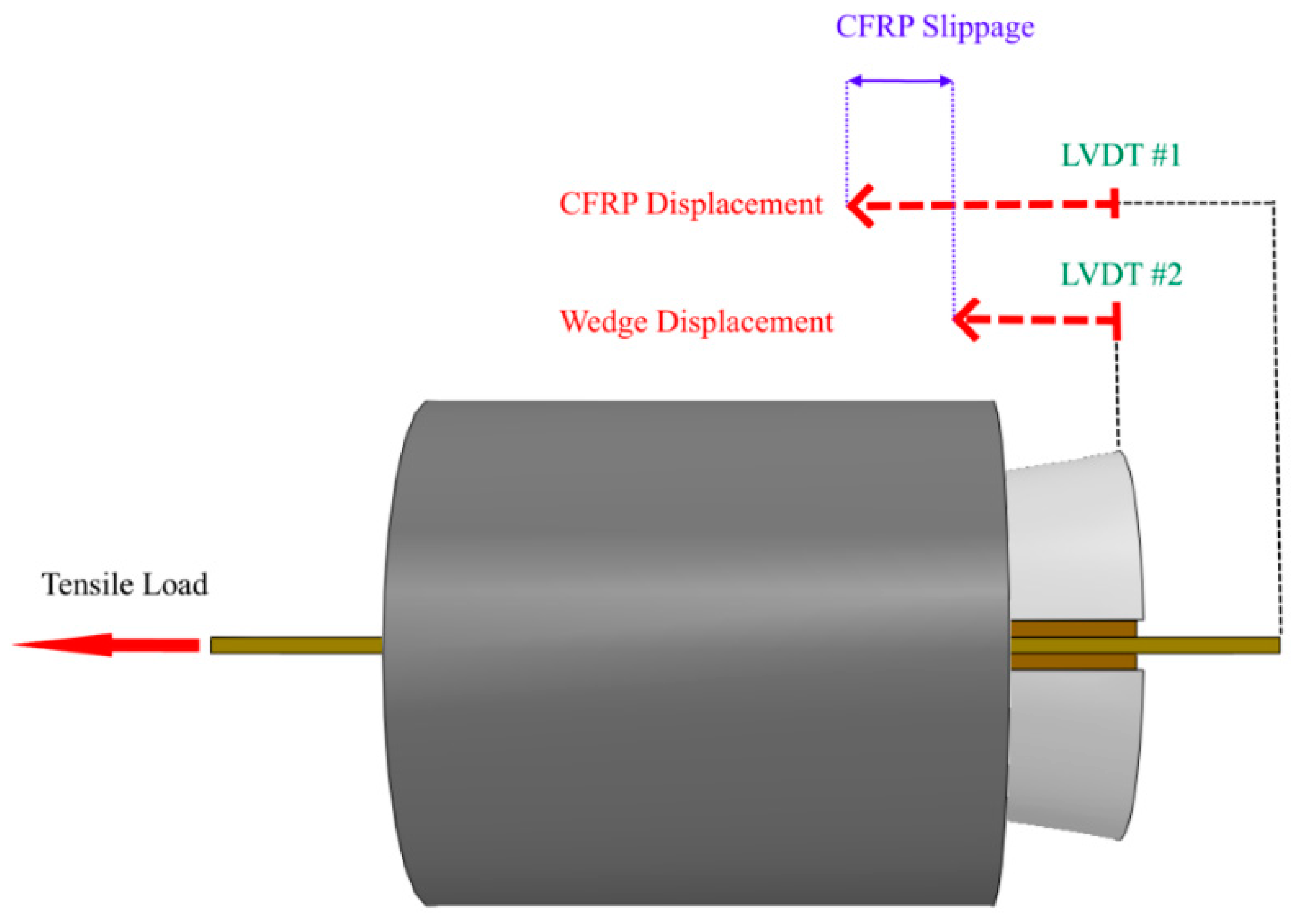
Figure 7.
Fracture mode of CFRP plate outside the anchorage. Reproduced from Alhusain and Al-Mayah (2022) [38] with permission from Springer Nature.
Figure 7.
Fracture mode of CFRP plate outside the anchorage. Reproduced from Alhusain and Al-Mayah (2022) [38] with permission from Springer Nature.
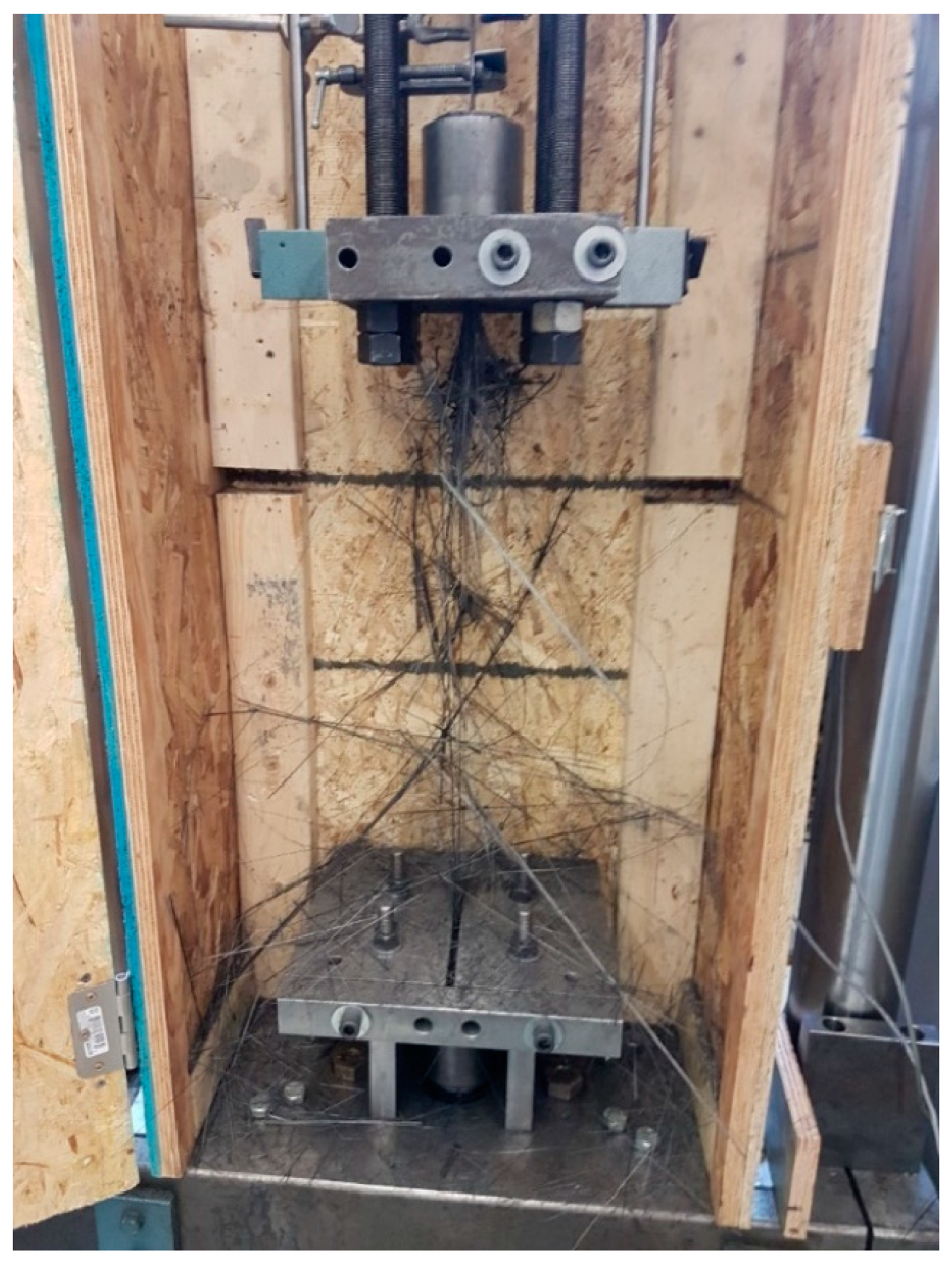
Figure 8.
Deformed copper sleeves after testing.

Figure 9.
CFRPs’ failure load under (A) high and (B) low presetting levels.

Figure 10.
Tensile load vs. CFRP displacement for (A) high-presetting, and (B) low-presetting tests.
Figure 10.
Tensile load vs. CFRP displacement for (A) high-presetting, and (B) low-presetting tests.
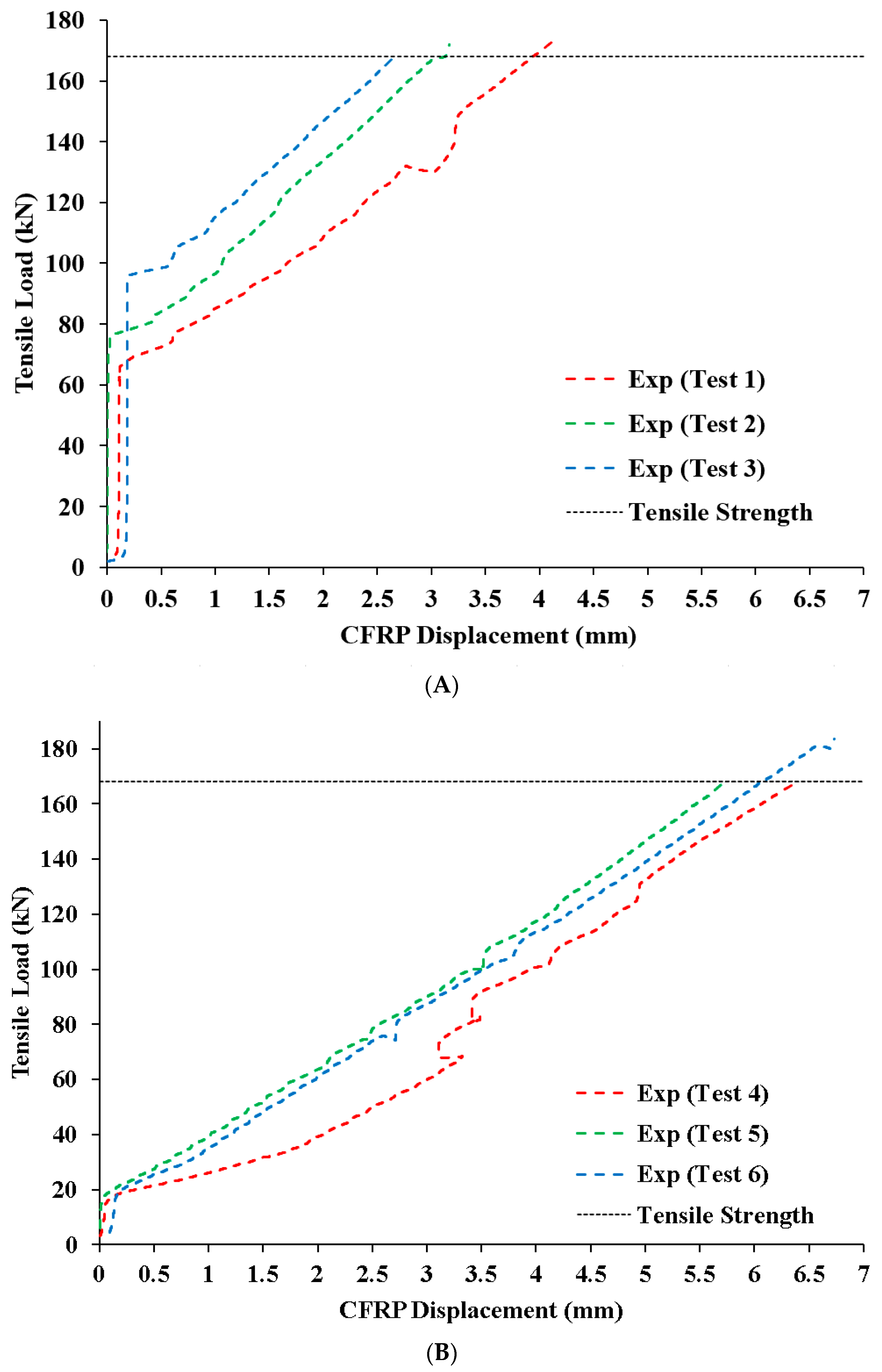
Figure 11.
Tensile load vs. CFRP slippage for (A) high-presetting and (B) low-presetting tests.

Figure 12.
Intact and fractured CFRP parts of CFRP plate.

Figure 13.
Plastically deformed (A) wedge and (B) barrel.
Disclaimer/Publisher’s Note: The statements, opinions and data contained in all publications are solely those of the individual author(s) and contributor(s) and not of MDPI and/or the editor(s). MDPI and/or the editor(s) disclaim responsibility for any injury to people or property resulting from any ideas, methods, instructions or products referred to in the content. |
© 2024 by the authors. Licensee MDPI, Basel, Switzerland. This article is an open access article distributed under the terms and conditions of the Creative Commons Attribution (CC BY) license (https://creativecommons.org/licenses/by/4.0/).
Share and Cite
MDPI and ACS Style
Alhusain, M.; Al-Mayah, A. Innovative Wedge Anchorage for CFRP Plates: Development and Testing. J. Compos. Sci. 2024, 8, 103. https://doi.org/10.3390/jcs8030103
AMA Style
Alhusain M, Al-Mayah A. Innovative Wedge Anchorage for CFRP Plates: Development and Testing. Journal of Composites Science. 2024; 8(3):103. https://doi.org/10.3390/jcs8030103
Chicago/Turabian StyleAlhusain, Mustafa, and Adil Al-Mayah. 2024. "Innovative Wedge Anchorage for CFRP Plates: Development and Testing" Journal of Composites Science 8, no. 3: 103. https://doi.org/10.3390/jcs8030103