Article

Fabrication and Ablation Properties of SiC Nanowires-Network Modified Carbon/Carbon–Ultrahigh Temperature Ceramics Composites

1
Shaanxi Key Laboratory of Green Preparation and Functionalization for Inorganic Materials, School of Material Science and Engineering, Shaanxi University of Science & Technology, Xi’an 710021, China
2
State Key Laboratory for Mechanical Behavior of Materials, School of Materials Science and Engineering, Xi’an Jiaotong University, Xi’an 710049, China
*
Author to whom correspondence should be addressed.
J. Compos. Sci. 2024, 8(3), 108; https://doi.org/10.3390/jcs8030108
Submission received: 23 January 2024 / Revised: 28 February 2024 / Accepted: 6 March 2024 / Published: 19 March 2024
(This article belongs to the Section Fiber Composites)

Abstract

:
In order to address the anti-ablation of carbon/carbon (C/C) composites, SiC nanowires (SiCnws) network-modified C/C-ZrB2-ZrC-SiC composites were prepared through the one-step precursor conversion method. With an optimized B-Si-Zr sol-precursor, uniformly dispersed SiCnws and ceramic particles forming an interlocking structure were synchronous in situ grown in the C/C matrix. During ablation, the partially oxidized SiCnws networks with molten SiO2 surface can stabilize the oxide protecting layer and heal the microcracks efficiently in combination with the refractory ZrO2 particles, thus significantly improving the anti-ablation properties of the composites. This study lays the foundation for the high temperature and long-term anti-oxidation and anti-ablation application of C/C composites in the aerospace industry.

Graphical Abstract

1. Introduction

As the key materials for the thermal protection systems of advanced space vehicles and their propulsion systems, carbon fiber-reinforced carbon (C/C) composites must operate in extreme environments above 2000 °C with complex airflow erosion and large gradient thermal shock [1,2,3]. Therefore, it is crucial to obtain C/C composites with good anti-ablation properties. Recently, ultrahigh temperature ceramics (UHTCs)-modified C/C composites (C/C-UHTCs) have been proven to be the most promising candidate [4,5,6]. Ultra-high temperature ceramics (UHTCs) generally refers to the carbides, nitrides, and borides of the transition metals, with melting points higher than 3000 °C and excellent oxidation ablation resistance [7]. In particular, the carbides and borides, such as ZrB2, ZrC, HfB2, and HfC, have attracted much attention because their high melting points coupled with their ability to form refractory oxide scales give them the ability to withstand temperatures in the 1900–2500 °C range [8]. With the introduction of UHTCs, an oxide protecting layer can be generated due to the oxidation of the UHTCs, which can efficiently decrease the contact between oxygen and the substrate, thus contributing to the anti-ablation of the composites [9,10,11]. However, the CTE mismatch between the ceramic phases (such as ZrB2, ~6.5 × 10⁻⁶ °C−1 [12]; ZrC, ~7.1 × 10⁻⁶ °C−1 [12]; ZrO2, 8.0~11 × 10−6 °C−1 [13]) with C/C (1~2 × 10⁻⁶ °C−1 [14]) cause thermal stress concentration and may induce penetrating cross cracks during the ablation. Generally, the greater the CTE mismatch, the larger the crack frequency will be. The cracks become the channels for oxygen diffusion and provide ways for the oxide protecting layer to be scoured away, which will accelerate carbon matrix oxidation and the failure of the composites [15,16,17]. Therefore, it is crucial to restrain the formation and propagation of the cracks and improve the stability of the oxide protecting layer during ablation.
SiC nanowires (SiCnws) have been widely applied as reinforcements to promote the toughness of ceramic composites due to their high specific strength, large aspect ratio, and harsh environment resistance [18,19,20]. Wang et al. [21] fabricated a nano-whisker SiC coating for C/C composites, and found that the CTE of the composites at 1000 °C was 2.69 × 10⁻⁶ °C−1, which was much lower than that of the composites with a dense SiC coating (5.80 × 10⁻⁶ °C−1). Chu et al. [22] investigated the influence of SiC nanowires on the oxidation protective ability of an SiC coating for C/C composites between room temperature and 1500 °C. It reveals that the CTE of the coated C/C samples with SiC nanowires is always below that of the coated C/C samples without SiC nanowires at the same temperature. Zhang et al. [23] investigated the CTE of bare C/C composites and the SiC-coated C/C composites with or without SiC nanowires from 850 to 1500 °C. The results showed that the CTE of the C/C-SiC sample with SiCnws was closer to that of bare C/C composites, thus improving its resistance to thermal shock. As is well known, the C/C substrates have the same thermal expansion behavior under the same conditions, so that the measured results can reflect the difference in CTE of these coatings [24]. These results suggest that the introduction of SiCnws could relieve CTE mismatch between the carbon matrix and the ceramic phases [25,26], thus decreasing the formation of microcracks. Furthermore, during oxidation, a molten silica scale glass can be formed, which can endow the composites with a good self-healing effect against cracks [27,28]. Therefore, there is a strong possibility that the CTE mismatch and self-healing problems of C/C-UHTCs composites can be solved if we fully utilize the properties of SiCnws and the UHTCs matrix synergistically [29,30,31]. If a ceramic matrix dispersed with SiCnws interwoven networks can be obtained, it can not only alleviate the CTE mismatch between C/C and the UHTCs to reduce the cracks formation, but also increase the length per unit area of the UHTCs/SiC interface and provide molten glass SiO2 continuously during oxidation. This is expected to help the ceramic matrix be more effective and efficient in forming the protective oxide layer and to heal the cracks. However, preparing SiCnws reinforced with the UHTCs multiphase ceramic matrix with a dispersed structure is challenging, due to the difficulty in controlling the distribution of the SiCnws. Moreover, the ratio of the SiCnws in the ceramic matrix is crucial. With a too low content of SiCnws, its effectiveness in forming a supporting skeleton network structure and providing molten silica rich glass is limited. On the other hand, with a too high content of SiCnws, the self-healing process cannot be achieved because of the limited pinning effect of the refractory ceramic particles and the low viscosity of the oxide layer. Therefore, the formation of SiCnws networks and its effect on the ablation behavior of the composites still need to be explored.
In our previous study [32,33,34], we reported a facile approach to preparing homogeneously dispersed SiCnws in ZrB2-ZrC-based UHTCs powders with a regulatable morphology and particle size distribution. In this method, the phase ratio of the ceramic matrix can be optimized by regulating the composition of the sol precursor. The SiCnws-reinforced multiphase ceramic matrix with a dispersed structure can be achieved by the in situ growth of SiCnws and the ceramic matrix synchronously through pyrolyzing the precursor. Therefore, an optimized structure and composition of the C/C-UHTCs composites with dispersed SiCnws networks should be obtained to provide clearly improved anti-ablation properties for C/C composites.

2. Experimental Section

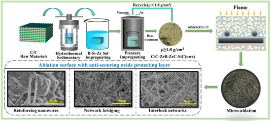
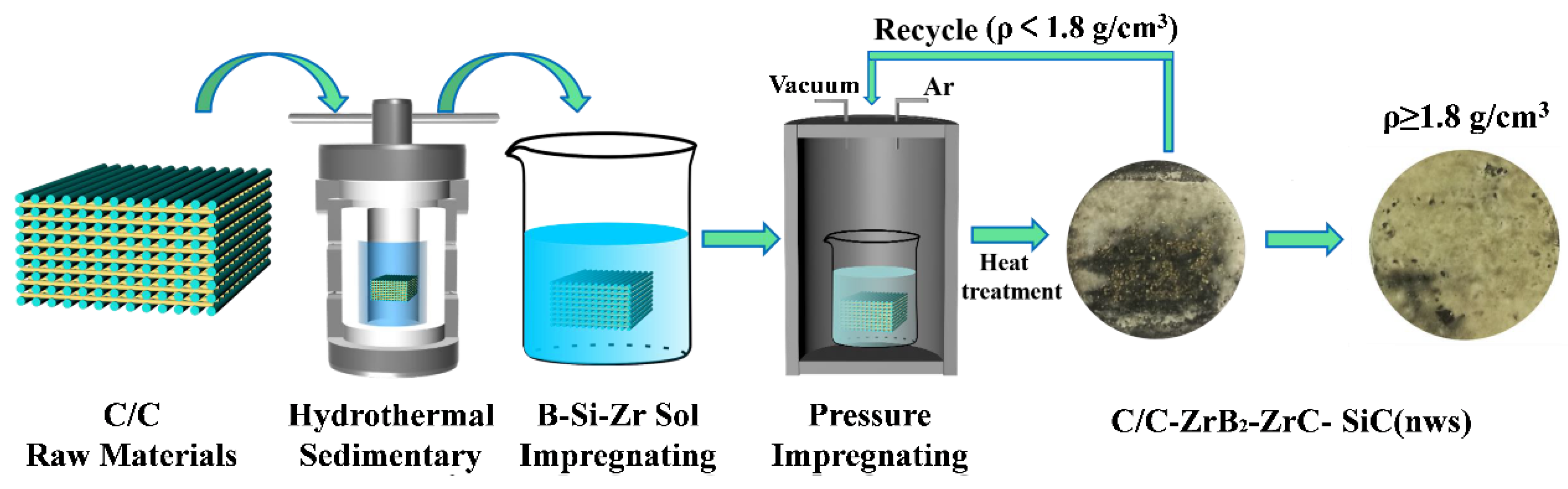
2.1. Preparation of the C/C-ZrB2-ZrC-SiC(nws) Composites

Figure 1 shows the schematic for the fabrication of SiCnws network-reinforced C/C-UHTCs composites (C/C-ZrB2-ZrC-SiC(nws)). T300 PAN-based carbon felts (0.45 g/cm3) were obtained from Yixing Tianniao High Technology Co., Ltd. (Yixing, China). Firstly, a hydrothermal carbon layer was deposited on the carbon fiber through hydrothermal treatment at 200 °C for 2 h using glucose as the carbon source. Secondly, B-Si-Zr sol precursors with various silicon contents were infiltrated into the carbon felt by vacuum impregnation, followed by dring and pyrolysis at 1600 °C for 2 h in flowing Ar atmosphere. The specific preparation method for the B-Si-Zr sol precursor and morphologies of their pyrolysis products are shown in our previous study [32,33]. Specifically, in each n(Si)/n(Zr) ratio range, i.e., n(Si)/n(Zr) < 6, 6 ≤ n(Si)/n(Zr) < 10, 10 ≤ n(Si)/n(Zr) < 14, 14 ≤ n(Si)/n(Zr) ≤ 18, the pyrolyzed products possess similar composition and morphology within the range. Moreover, the length of SiCnws in the ceramic matrix clearly grew with the increasing n(Si)/n(Zr) ratio. Therefore, considering the potential ability to form the SiCnws networks, the four precursors with n(Si)/n(Zr) values of 4, 8, 12, 16, which can produce SiCnws in different lengths, were chosen. Viscosities of the prepared sol precursors with n(Si)/n(Zr) values of 4, 8, 12, and 16 were 68, 45, 40, and 36 mPa·s, respectively. Accordingly, the samples were labeled as 4SZ, 8SZ, 12SZ, and 16SZ, respectively. We repeated the above precursor–infiltration–pyrolysis (PIP) process 15 times until the sample density reached 1.8 g/cm3. Finally, resin carbon was infiltrated to fill the pores through vacuum impregnation and carbonization. Final density of the composites measured by Archimedes method was 2.2 g/cm3.

2.2. Ablation Tests

Ablation tests were conducted using a plasma torch (Multiplaz 3500, Multiplaz, Shenzhen, China) with working voltage of 160 V and working current of 6 A [35,36]. The ablation specimens were cut into a cylindrical shape (Ø 30 × 10 mm). Distance between the specimens and the nozzle was set to 10 mm. The maximum temperature region of the flame is about 2 mm. For each composition, three samples were prepared for ablation tests. The ablation time was 30 s for each test. The linear (Rl, mm·s−1) ablation rates with an accuracy of ±0.1 μm/s and mass ablation rates (Rm, g·cm−2·s−1) with an accuracy of ±0.1 mg/s were the average of three samples tested at each testing condition by calculating the thickness and mass changes in the specimens before and after ablation according to the following formulas [37]:
R l = d 0 d 1 t
R m = m 0 m 1 S · t
where d0 and d1 are the thicknesses of the samples before and after ablation, respectively; m0 and m1 are the masses of the samples before and after ablation, respectively; S is the ablation surface area; t is the ablation time.

2.3. Characterization

Viscosities of the precursors were detected by the rotational viscometer (NDJ-1S, Shanghai, China). Phase analysis was recorded by a D/max-2200PC X-ray diffraction with Cu K radiation (XRD) scanning at 4°/min. Microstructure of the samples were investigated by a FEI Verios 460 scanning electron microscopy (SEM) with energy-dispersive spectroscopy (EDS, Oxford INCA) (FEI, HI, USA).

3. Results and Discussion

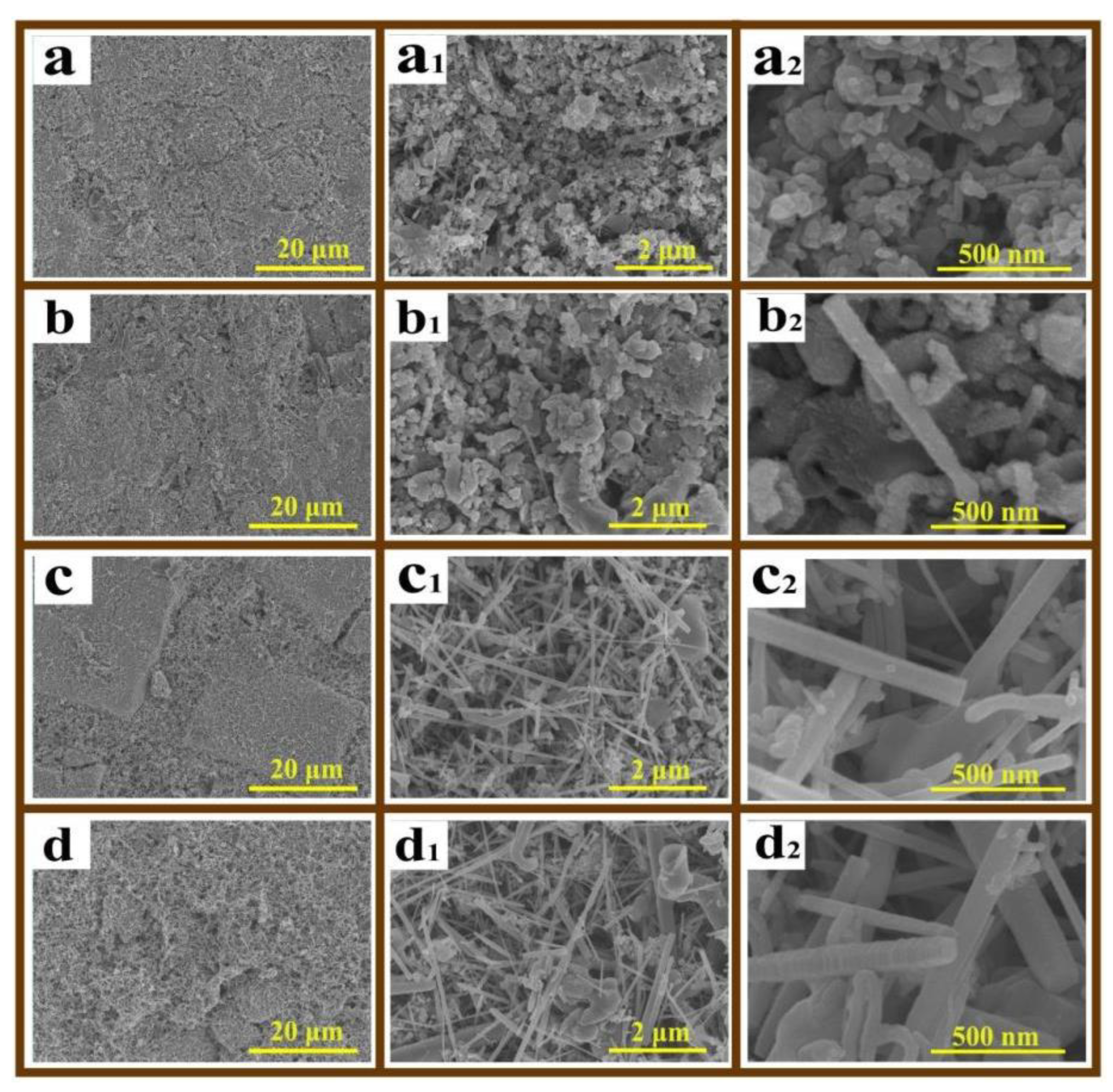
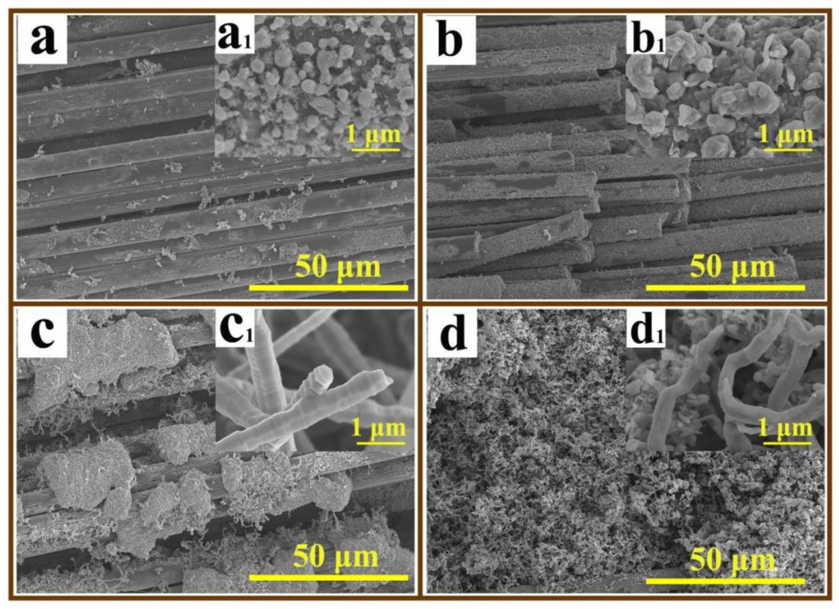
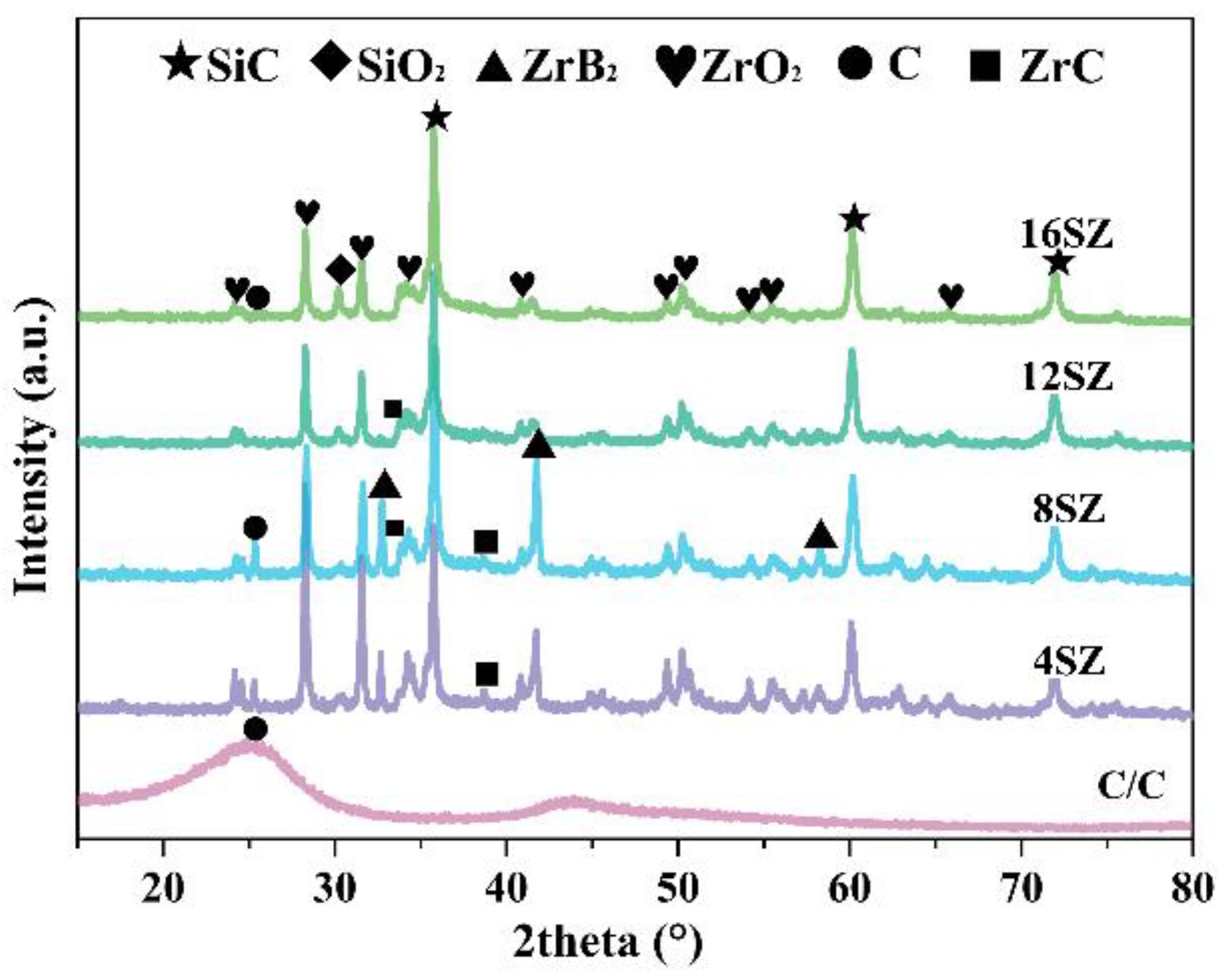
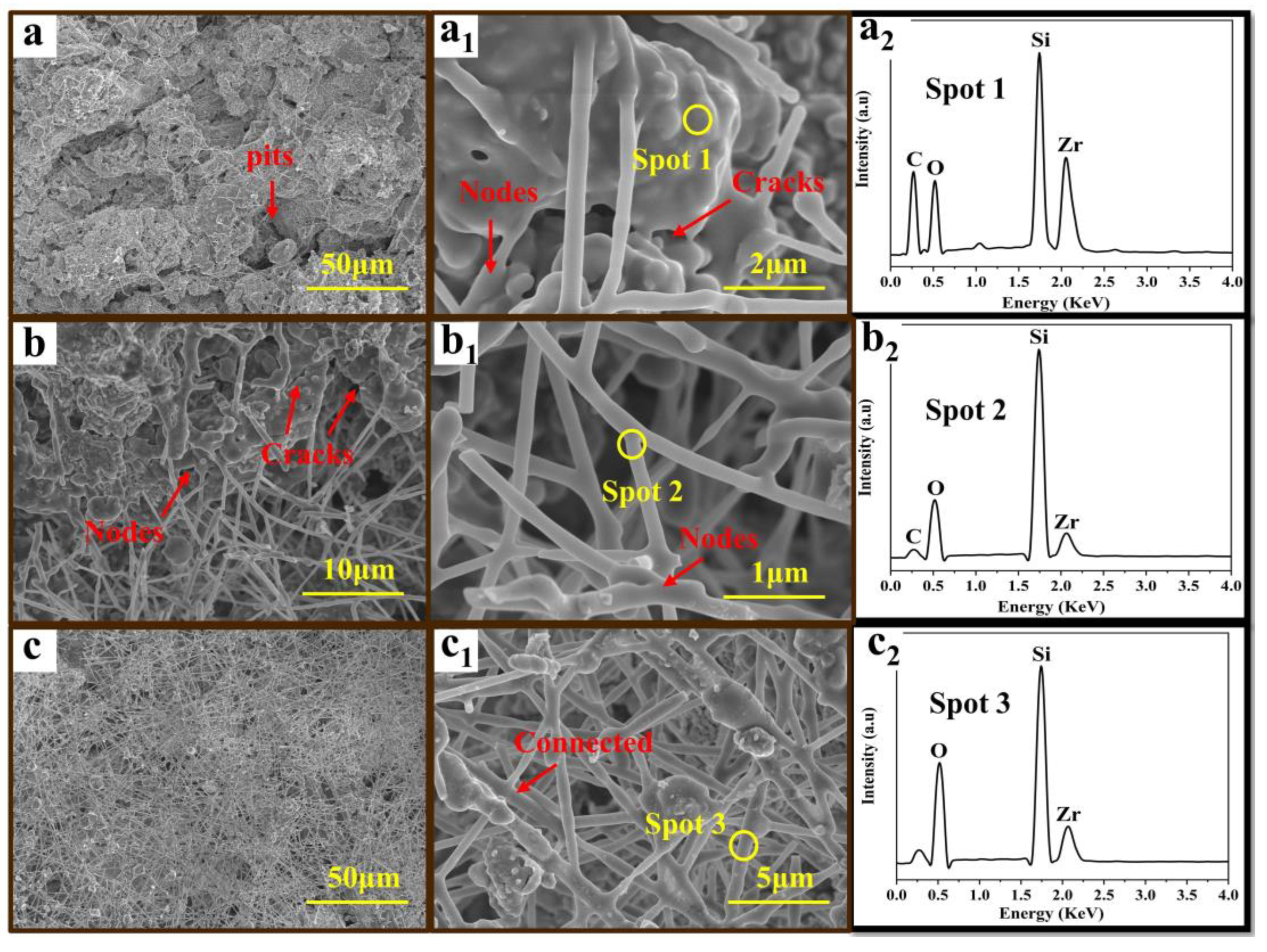
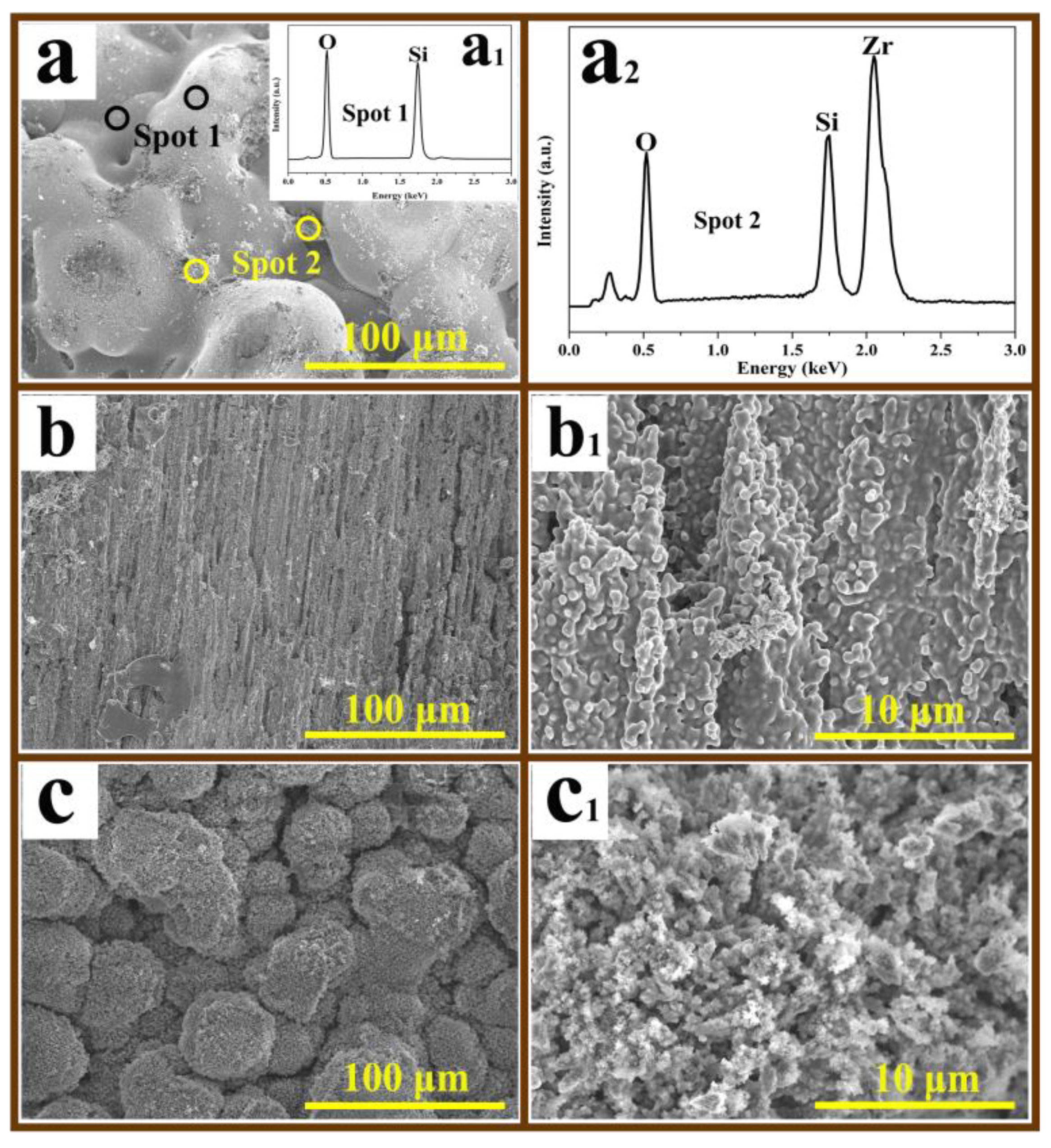
3.1. Microstructure and Composition

Figure 2 illustrates the surface morphology of the composites after undergoing the PIP process twice. As can be seen, the content of the SiCnws clearly increased with the increase in the silicon content in the precursor. For 4SZ and 8SZ, mainly ceramic particles and tiny amounts of SiCnws can be observed. For 12SZ and 16SZ, a large amount of SiCnws was formed. The length of the SiCnws varies from a few micrometers to tens of micrometers. And the diameter also varies from several nanometers to tens of nanometers. The large aspect ratio (length/diameter) and the various length of the SiCnws contribute to an enhanced toughening effect. Moreover, with an appropriate silicon content (12SZ), the ceramic particles with a diameter of about 50–100 nm dispersed randomly in the gaps of the SiCnws networks, indicating that SiCnws networks-reinforced multiphase ceramic matrix with a dispersed structure can be obtained by the in situ growth of SiCnws and ceramic particles simultaneously.
Figure 3 shows a cross-sectional images of the composites with various silicon contents after undergoing the PIP process twice. For the samples 4SZ and 8SZ, the ceramic particles are mainly located on the surface of the carbon fibers. And the sample with a higher silicon content shows a denser ceramic layer (8SZ). For the sample 12SZ, SiCnws with a diameter of about 500 nm are uniformly distributed in the matrix including the fiber surface and their gaps. In particular, the SiCnws are interwoven with each other forming a network structure. Meanwhile, the ceramic particles show an aggregated morphology but an even distribution. For the sample 16SZ, uniform and fine ceramic particles with uniformly distributed warm-like SiCnws but a smaller diameter can be observed. As is known, an appropriate local CO and SiO gas supersaturation is required for the growth of SiCnws. And these reaction gases are generated from the pyrolysis of the B-Si-Zr precursor. With an increased silicon content, the SiCnws begin to grow when the gas supersaturation meets the requirements. But with a high gas supersaturation, the deposition rate of the gases is greater than the growth of nanowires; thus, a warm-like morphology, usually with a high number of defects, is obtained. Based on the above analysis, with an adjusted silicon content in the precursor, SiCnws can be successfully introduced into the matrix and surface of the composites forming an interwoven network structure, which could produce an enhanced toughing effect on the surface and substrate during the ablation process.
Figure 4 presents the XRD results of the composites with various silicon contents. The XRD patterns show the phase compositions of SiC, SiO2, ZrB2, ZrC, and ZrO2 for all of the samples. For sample 4SZ, ZrB2, SiC, and ZrO2 are the main phase. By increasing the silicon content, a decrease in ZrO2 content and an increase in ZrB2 can be observed, confirming the further carbothermal reaction caused by the grain-refining effect of SiO2 [34]. However, after further increasing the silicon content, a clear decrease in the ZrB2 peak intensity was observed. This may have resulted from the full division and easier evaporation of B2O3 due to the excessive silicon.
Figure 5 presents cross-sectional images of the composites with various silicon contents after densification. It shows that both the number of pores and the sizes of pores decreased as the silicon content increased, suggesting that free spaces between the individual woven fabrics can be filled completely by impregnating them with a B-Si-Zr sol-precursor. With the increase in silicon content, the viscosity of the sol precursor decreases because of the increased tetraethyl orthosilicate content in the sol. For the samples prepared with a low silicon content, there are clear incomplete infiltration defects, which may be due to the high viscosity of the sol precursor with a low silicon content. For the samples prepared with a high silicon content, a dense microstructure with a small number of matrix shrinkage defects can be observed. Therefore, the infiltration of the prepared B-Si-Zr sol precursor of appropriate viscosity can contribute to the fully filled of the porous structure.

3.2. Ablation Characteristics

The compositions of the composites before and after ablation are shown in Figure 6. All the samples show a similar phase composition, but a clearly increased ZrO2 and SiO2 content and decreased SiC content can be noticed after ablation. This result indicates that part of the ceramic matrix was oxidized during ablation, and oxidation products which are mainly composed of ZrO2 and SiO2 were formed. Figure 7 shows the ablation morphologies of the composites with various silicon contents. Compared to the other samples with a clear peeling off of the protecting layer, the ablation surface of composite 12SZ shows a continuous and integral structure, suggesting that a stable and anti-scouring oxide layer was formed during ablation. After ablation, the Rm and Rl of 12SZ were 0.11 mg·cm−2·s−1 and 0.08 um·s−1 (as shown in Table 1), respectively, indicating a good ablation resistance.
As for the ablation mechanism of the C/C-UHTCs composites, it has been widely studied. A common conclusion is that the formation of an oxide protecting layer on the ablated surface contributes to the improvement of anti-ablation properties [38,39,40]. In this work, it is the ZrO2-SiO2 products. If the bonding strength of the oxide protecting layer is not high enough, the oxide layer can be scoured away by the strong plasma flame, thus leading to the failure of the composites. Therefore, the formation and structural evolution of the oxide layer will be focused on and discussed in detail in the following section.
According to fluid mechanics, a high viscosity of the ablation products would provide high shear strength to endure the scouring of the ablation flame. On the other hand, a suitable viscosity is necessary to provide a good liquidity to heal the cracks. Therefore, the viscosity of the ablation products is important for the ablation resistance of the composites. In the ablation process, the ZrO2-SiO2 products are formed due to the oxidation of ZrB2-ZrC-SiC ceramics. In particular, under the plasma ablation temperature (∼2300 °C), they are the solid ZrO2 (melting point, 2680 °C) and the molten glassy SiO2 liquid phase (melting point, 1723 °C) according to the phase diagram of the ZrO2-SiO2 binary system [41]. The ablation products can be regarded as a ZrO2-SiO2 suspension system. According to the semiempirical equation of Krieger and Dougherty for monodisperse suspensions [42], the relative viscosity is a rapidly increasing function of the solid fraction.
η r = η η L
x = 1 Φ Φ m η Φ m
where η is the viscosity of the suspension, ηL is the viscosity of the liquid phase, ηr is the relative viscosity of the suspension, Φ and [η] are the volume fraction and the intrinsic viscosity of the particles, and Φm is the maximum packing fraction of particles. Generally, the crystal and liquid phases coexist up to Φm = 0.545.
The viscosity of SiO2 at ∼2300 °C is 4.5 Pa∙s, which can be estimated using the Vogel–Fulcher–Tammann equation [43]. When the volume fraction of solid phase in the ablation products reached 0.1, 0.2, 0.3, 0.4, and 0.5, the relative viscosity increased to 1.5, 2.5, 5, 14, and 147, respectively [37]. When the volume fraction of the ablation products exceeds the maximum packing fraction of particles (Φm, 0.545), there is not sufficient fluid to lubricate the relative motion of particles and the viscosity rises to infinity [42]. This suggests that the viscosity of the ZrO2-SiO2 ablation products increased exponentially with the increase in ZrO2 content.
For sample 4SZ (Figure 8), the viscosity of the ablation products (mainly SiO2 and ZrO2) was high due to the low SiO2 content. An oxide layer can ensure the ablation flame, but it cannot cover the ablated surface rapidly, i.e., it possesses no self-healing ability; therefore, a porous and discontinuous layer was formed in the ablation center. On the other hand, due to the CTE difference between the C/C matrix and the oxide protecting layer, microcracks were easily form and the oxide layer was easy to peel off. Without the efficient protection of an oxidation layer, oxidative erosion of carbon fibers with scour marks can be observed in the transition area. In the rim area, a layer composed of spherical or hollow spheres in a size of about 20–100 um formed by airflow erosion can be observed.
With the increase in silicon content (6SZ), the morphology of the ablation center became smooth and had a strong integrity (as shown in Figure 9), indicating its increased self-healing ability. However, the content of SiCnws was not high enough to form a supported network and cannot provide enough molten SiO2 to heal the cracks. Discontinuous and porous structures formed by ZrO2 particles as confirmed by EDS analysis were formed in the transition area. In the rim area, a large amount of spherical and broken hollow spherical particles can be observed. With a higher SiO2 content (Figure 9(c2)), molten SiO2 of low viscosity was scoured to the rim area of the composites under high-speed airflow, forming a spherical morphology.
With the introduction of SiCnws networks into the ceramic matrix (12SZ), the obtained composites exhibit superior ablation property. As can be seen, the ablation surface shows structural integrity with no presence of the peeling off of the oxide layer (Figure 10a). Although big pits can clearly be observed, there are no large penetrating cracks present on the surface. Moreover, the SiCnws network remained after ablation and they were uniformly distributed in the whole area of the ablation surface. And the oxide products formed had a relatively dense molten structure (Figure 10b), which was composed of large amounts of molten oxides of SiO2 and ZrO2 (Figure 10(a2)) with bridging and reinforcing nanowires (Figure 10(a1,b,b1)). Moreover, the EDS analysis (Figure 10(b2,c2)) shows that the element composition of the nanowires is Si, O, and Zr, verifying that the surface of the SiCnws has been oxidized into SiO2 phases, forming a molten SiO2 surface layer. The molten SiO2 surface contributes greatly to the formation of the interlocking nanowires networks and the healing of defects as they can easily integrate with each other in the molten state. The strengthening effect of the nanowires can be remarkably enhanced by interconnecting with each other. As the nanowires melt and connect with each other, the surrounding pores or microcracks are filled and sealed. Therefore, in the early stage of ablation, the formed molten SiO2 oxides can flow and heal the microcracks in combination with the pinning effect of the ZrO2 particles as confirmed by the EDS analysis in Figure 10(a2), thus undergoing a self-healing process. Nanowires in whole or in part are literally rooted into the oxide products, strengthening or bridging the oxide layer, thus greatly improving the stability of the oxide layer. This can be proved by the traces of the cracks being healed, and the accumulation of molten oxides at the connected nodes (Figure 10(a1,b)). In Figure 10b, large scales of molten products bridged by nanowires networks can be observed, which is another common structure present on the ablation surface. The nanowires melted and connected with each other and formed a branching structure with one end rooted in the molten oxides (Figure 10(b1)). The oxide products were snared and pinned by the networks, thus avoiding being scoured away. Moreover, in the rim area, a large number of nanowires cross connected with each other can be observed. The relatively dense and interlocking networks can resist the scouring and heat attack, thus preventing the matrix from being ablated. Therefore, it can be concluded that the SiCnws networks can stabilize the oxide layer, while restraining and healing the microcracks, thus significantly improving the ablation resistance of the composites.
For sample 16SZ (Figure 11), due to the high SiC content, the ablation products high in SiO2 content possessed low viscosity and good flowability. During ablation, the ablation products were easy to blow away and spherical structures were easy to form. Therefore, a oxide protecting layer with a smooth but rough surface resulting from the molten spherical particles accumulation was formed in the central area. As confirmed by the EDS analysis, the spherical particles mainly consisted of SiO2 with ZrO2 particles deposited on their surface. In the transitional area, scour marks of V-grooves along the ablation flow direction were left. In the rim area, a porous and loose layer composed of spherical agglomerates formed by particle accumulation can be observed.
Based on the above analysis, it can be concluded that ratio of the SiCnws in the ceramic matrix is detrimental to the structure’s stability of the formed oxide protecting layer. By increasing the silicon content in the precursor, the silicon content is high enough to support the growth of SiCnws and form a supporting skeleton network structure. Furthermore, the appropriate content of ZrO2 can ensure the high viscosity of the oxide products to ensure the ablation flame. The formed SiCnws network can strength the oxide layer and provide molten silica-rich glass to heal the microcracks, thus effectively improving the stability of the oxide layer. However, when further increasing the silicon content, although a large amount of SiCnws can be formed, the oxide protecting layer is easy to be sourced away due to the insufficient volume fraction of the refractory ZrO2 particles.

3.3. Ablation Mechanism

For the common C/C-UHTCs composites, the CTE mismatch between the ceramic phases with the C/C matrix could cause thermal stress concentration, promote the initiation and rapidly propagation of microcracks, and finally lead to their oxidation failure (Figure 12a). For the SiCnws interwoven networks-reinforced C/C-UHTCs composites, some SiCnws are positioned at the surface of the composite, some are completely growth in the matrix, while others are partially rooted in the dense matrix, thus forming a uniformly dispersed SiCnws interwoven network through the whole composite. The SiCnws connected with each other to form the reinforced structure, while adhering and bond ceramic particles to form a dense matrix. And the presence of the dispersed SiCnws networks can efficiently reduce the CTE difference between the ceramic phases and the carbon matrix, thus relieving the stress concentration and restraining the formation of microcracks. During ablation, ceramic phases are oxidized into ZrO2-SiO2 composite oxides forming an oxide protecting layer. The remaining SiCnws networks with a molten SiO2 surface can join and lock the ceramic particles and their oxide products together as an integrated structure, thus improving the stability of the oxide layer. Moreover, the propagation of cracks can be effectively restrained due to the strengthening effect of the nanowires (Figure 12b). Furthermore, SiCnws at the ablation surface are completely or partially oxidized into a molten and flowable SiO2 phase, which can further enhance their interaction with the surrounding ceramics particles. Meanwhile, the appropriate volume fraction of the dispersed ZrO2 phase which has a high melting point can restrict the movement of the oxide product layer, thus improving its resistance to peeling off from the matrix. Furthermore, due to the larger contact interface with the ceramic matrix, oxidized SiCnws networks can fill and heal the microcracks in the local position more quickly in combination with the pinning effect of the ZrO2 ceramic particles, thus providing an efficient self-healing ability to the protecting film. Finally, a continuous and anti-scouring oxide protecting layer with efficient self-healing abilities was formed (Figure 12c). And the anti-ablation abilities of the composites were enhanced.

4. Conclusions

C/C-ZrB2-ZrC-SiC(nws) composites were prepared by pyrolyzing B-Si-Zr gel precursors using cyclic impregnation and pyrolyzing processes. SiC nanowires forming an interwoven network were grown in situ in the C/C matrix with the synchronous generation of the ZrB2, ZrC, SiC and ZrO2 ceramic particles. When the molar ratio of silicon to zirconium was 12, the obtained composites showed good anti-ablation properties. During ablation, the SiCnws were partially oxidized forming a molten SiO2 surface, which contributed greatly to the formation of reinforcing interlock networks, while filling and healing the cracks efficiently. In combination with the appropriate volume and content of the ZrO2 particles, the interlocking networks can stabilize the oxide layer, thus the anti-ablation of the modified C/C composites was greatly enhanced.

Author Contributions

Conceptualization, C.L. (Changqing Liu); methodology, C.L. (Changqing Liu); software, W.W.; validation, Y.W., C.L. (Changqing Liu) and L.C.; formal analysis, X.Y. and C.L. (Changqing Liu); investigation, L.C., W.W. and X.Y.; resources, C.L. (Chengxin Li); data curation, X.Y.; writing—original draft preparation, L.C.; writing—review and editing, C.L. (Changqing Liu); visualization, X.Y.; supervision, Y.W. and C.L. (Chengxin Li); project administration, Y.W.; funding acquisition, Y.W. and C.L. (Changqing Liu). All authors have read and agreed to the published version of the manuscript.

Funding

This work has been supported by the National Natural Science Foundation of China (Grant No. 51702194 and 52173214), the Natural Science Foundation of Shaanxi Province (Grant No. 2023-JC-YB-384), and the Youth Innovation Team of Shaanxi Universities (2022-70).

Data Availability Statement

The data are available upon request and please contact the corresponding author to access the data.

Conflicts of Interest

The authors declare that they have no known competing financial interests or personal relationships that could have appeared to influence the work reported in this paper.

References

  1. Savage, G. Carbon-Carbon Composites; Chapman & Hall: London, UK, 1993; pp. 198–209. [Google Scholar]
  2. Leonard, C.P.; Amundsen, R.M.; Bruce, W.E. Hyper-X Hot structures design and comparison with flight data. In Proceedings of the AIAA/CIRA International Space Planes and Hypersonic Systems and Technologies Conference, AIAA-2005-3438, 1th, Capua, Italy, 16–20 May 2005. [Google Scholar]
  3. Zhu, S.B.; Zhang, G.X.; Bao, Y.L.; Sun, D.Y.; Zhang, Q.; Meng, X.L.; Hu, Y.; Yan, L.S. Progress in preparation and ablation resistance of ultra-high-temperature ceramics modified C/C composites for extreme environment. Rev. Adv. Mater. Sci. 2023, 62, 20220276. [Google Scholar] [CrossRef]
  4. Jiao, X.Y.; Tan, Q.; He, Q.C.; Qing, M.C.; Wang, Y.Q.; Yin, X.M. Cyclic ablation behavior of mullite-modified C/C-HfC-SiC composites under an oxyacetylene flame at about 2400 °C. J. Eur. Ceram. Soc. 2023, 43, 4309–4321. [Google Scholar] [CrossRef]
  5. Pan, X.H.; Niu, Y.R.; Xu, X.T.; Zhong, X.; Shi, M.H.; Zheng, X.B.; Ding, C.X. Long time ablation behaviors of designed ZrC-SiC-TiC ternary coatings for environments above 2000 °C. Corros. Sci. 2020, 170, 108645. [Google Scholar] [CrossRef]
  6. Hu, C.L.; Pang, S.Y.; Tang, S.F.; Wang, S.J.; Huang, H.T.; Cheng, H.M. Ablation and mechanical behavior of a sandwich-structured composite with an inner layer of Cf/SiC between two outer layers of Cf/SiC-ZrB2-ZrC. Corros. Sci. 2014, 80, 154–163. [Google Scholar] [CrossRef]
  7. Monteverde, F. The thermal stability in air of hot-pressed diboride matrix composites for uses at ultra-high temperatures. Corros. Sci. 2005, 47, 2020–2033. [Google Scholar] [CrossRef]
  8. Tang, S.F.; Deng, J.Y.; Wang, S.J.; Liu, W.C.; Yang, K. Ablation behaviors of ultra-high temperature ceramic composites. Mater. Sci. Eng. A 2007, 465, 1–7. [Google Scholar] [CrossRef]
  9. Jiao, X.Y.; He, Q.C.; Qing, M.C.; Wang, Y.Q.; Yin, X.M. Ablation behavior of C/C-Zr1-xHfxC-SiC composites under an oxyacetylene flame at above 2500 °C. J. Mater. Res. Technol. 2023, 24, 3235–3251. [Google Scholar] [CrossRef]
  10. Liu, C.X.; Cao, L.X.; Chen, J.X.; Xue, L.; Tang, X.; Huang, Q.Z. Microstructure and ablation behavior of SiC coated C/C-SiC-ZrC composites prepared by a hybrid infiltration process. Carbon 2013, 65, 196–205. [Google Scholar] [CrossRef]
  11. Jin, X.C.; Fan, X.L.; Lu, C.S.; Wang, T.J. Advances in oxidation and ablation resistance of high and ultra-high temperature ceramics modified or coated carbon/carbon composites. J. Eur. Ceram. Soc. 2018, 38, 1–28. [Google Scholar] [CrossRef]
  12. Guo, S.Q.; Kagawa, Y.; Nishimura, T.; Chung, D.; Yang, J.M. Mechanical and physical behavior of spark plasma sintered ZrC-ZrB2-SiC composites. J. Eur. Ceram. Soc. 2008, 28, 1279–1285. [Google Scholar] [CrossRef]
  13. Song, X.M.; Ding, Y.; Zhang, J.M.; Jiang, C.F.; Liu, Z.W.; Lin, C.H.; Zheng, W.; Zeng, Y. Thermophysical and mechanical properties of cubic, tetragonal and monoclinic ZrO2. J. Mater. Res. Technol. 2023, 23, 648–655. [Google Scholar] [CrossRef]
  14. Liao, X.L.; Li, H.J.; Xu, W.F.; Li, K.Z. Study on the thermal expansion properties of C/C composites. J. Mater. Sci. 2007, 42, 3435–3439. [Google Scholar] [CrossRef]
  15. Cheng, Y.; Hu, P.; Zhang, W.Z.; Ma, C.; Feng, J.X.; Fan, Q.P.; Zhang, X.H.; Du, S.Y. One-step introduction of ZrC-SiC inside carbon fabric to fabricate high homogeneous and damage-tolerant composite inspired by vibration. J. Eur. Ceram. Soc. 2019, 39, 2251–2256. [Google Scholar] [CrossRef]
  16. Oana, M.M.; Neff, P.; Valdez, M.; Powell, A.; Packard, M.; Walker, L.S.; Corral, E.L. Oxidation behavior of aerospace materials in high enthalpy flows using an oxyacetylene torch facility. J. Am. Ceram. Soc. 2015, 98, 1300–1307. [Google Scholar] [CrossRef]
  17. Chen, X.W.; Feng, Q.; Zhou, H.J.; Dong, S.M.; Wang, J.X.; Cao, Y.P.; Kan, Y.M.; Ni, D.W. Ablation behavior of three-dimensional Cf/SiC-ZrB2-ZrC2 composites prepared by a joint process of sol-gel and reactive melt infiltration. Corros. Sci. 2018, 134, 49–56. [Google Scholar] [CrossRef]
  18. Wang, C.; Xia, L.; Zhong, B.; Yang, H.; Huang, L.N.; Xiong, L.; Huang, X.X.; Wen, G.W. Fabrication and mechanical properties of carbon fibers/lithium aluminosilicate ceramic matrix composites reinforced by in-situ growth SiC nanowires. J. Eur. Ceram. Soc. 2019, 39, 4625–4633. [Google Scholar] [CrossRef]
  19. Zhang, Z.F.; Sha, J.J.; Dai, J.X.; Zu, Y.F.; Lv, Z.Z. Enhanced fracture properties of ZrB2-based composites by in-situ grown SiC nanowires. Adv. Appl. Ceram. 2019, 118, 137–144. [Google Scholar] [CrossRef]
  20. Wang, W.; Fu, Q.; Tan, B. Effect of in-situ grown SiC nanowires on the mechanical properties of HfC-ZrB2-SiC modified C/C composites. J. Alloys Compd. 2017, 726, 866–874. [Google Scholar] [CrossRef]
  21. Wang, C.; Guo, B.; Lu, P.; Xu, Q.; Tu, R.; Kosinova, M.; Zhang, S. Fabrication of porous SiC nanostructured coatings on C/C composite by laser chemical vapor deposition for improving the thermal shock resistance. Ceram. Int. 2022, 48, 12450–12459. [Google Scholar] [CrossRef]
  22. Chu, Y.H.; Fu, Q.G.; Li, H.J.; Li, K.Z.; Zou, X.; Gu, C.G. Influence of SiC nanowires on the properties of SiC coating for C/C composites between room temperature and 1500 °C. Corros. Sci. 2011, 53, 3048–3053. [Google Scholar] [CrossRef]
  23. Zhang, J.P.; Fu, Q.G.; Qu, J.L.; Yuan, R.M.; Li, H.J. Blasting treatment and chemical vapor deposition of SiC nanowires to enhance the thermal shock resistance of SiC coating for carbon/carbon composites in combustion environment. J. Alloys Compd. 2016, 666, 77–83. [Google Scholar] [CrossRef]
  24. Feng, T.; Li, H.J.; Fu, Q.G.; Shen, X.T.; Wu, H. Microstructure and oxidation of multi-layer MoSi2-CrSi2-Si coatings for SiC coated carbon/carbon composites. Corros. Sci. 2010, 52, 3011–3017. [Google Scholar] [CrossRef]
  25. Zhang, M.Y.; Li, K.Z.; Shi, X.H.; Tan, W.L. Effects of SiC interphase on the mechanical and ablation properties of C/C-ZrC-ZrB2-SiC composites prepared by precursor infiltration and pyrolysis. Mater. Des. 2017, 122, 322–329. [Google Scholar] [CrossRef]
  26. Wen, S.Q.; Li, K.Z.; Song, Q.; Shan, Y.C.; Li, Y.Y.; Li, H.J.; Ma, H.L. Enhancement of the oxidation resistance of C/C composites by depositing SiC nanowires onto carbon fibers by electrophoretic deposition. J. Alloys Compd. 2015, 618, 336–342. [Google Scholar] [CrossRef]
  27. Weng, Y.Q.; Yang, X.; Chen, F.X.; Fang, C.Q.; Zhang, X.X.; Shi, A.H.; Huang, Q.Z. Ablative property and mechanism of SiC-CuxSiy modified C/C-ZrC composites prepared by a rapid method. J. Eur. Ceram. Soc. 2023, 43, 4602–4615. [Google Scholar] [CrossRef]
  28. Ouyang, H.B.; Li, C.Y.; Huang, J.F.; Cao, L.Y.; Fei, J.; Lu, J.; Xu, Z.W. Self-healing ZrB2–SiO2 oxidation resistance coating for SiC coated carbon/carbon composites. Corros. Sci. 2016, 110, 265–272. [Google Scholar]
  29. Yang, X.; Huang, Q.Z.; Su, Z.A.; Chang, X.; Xue, L.; Zhong, P.; Li, J. Ablative property and mechanism of C/C-ZrB2-ZrC-SiC composites reinforced by SiC networks under plasma flame. Corros. Sci. 2016, 107, 9–20. [Google Scholar]
  30. Xie, X.M.; Tang, X.; Su, Z.A.; Liao, J.J.; Yang, C.; Huang, Q.Z. Oxidation and ablation behaviours of a SiCnw@SiC-Si coating fabricated for carbon-fibre-reinforced carbon-matrix composites via thermal evaporation and gaseous silicon infiltration. Ceram. Int. 2023, 49, 9130–9137. [Google Scholar] [CrossRef]
  31. Xie, A.L.; Zhang, B.; Ge, Y.C.; Peng, K.; Xu, P.; Wang, X.D.; Feng, Z.R.; Yi, M.Z.; Zhou, Z. Effect of the incorporation of SiC nanowire with double protective layers on SiC coating for C/C composites. J. Eur. Ceram. Soc. 2023, 43, 4636–4644. [Google Scholar] [CrossRef]
  32. Liu, C.Q.; Yuan, X.X.; Wang, W.T.; Liu, H.L.; Li, C.X.; Wu, H.; Hou, X.H. In-situ fabrication of ZrB2-ZrC-SiCnws hybrid nanopowders with tuneable morphology SiCnws. Ceram. Int. 2022, 48, 4055–4065. [Google Scholar] [CrossRef]
  33. Liu, C.Q.; Zhang, L.Y.; Li, C.X.; Wu, H.; Hou, X.H. Preparation of ZrB2-ZrC-SiC-ZrO2 nanopowders with in-situ grown homogeneously dispersed SiC nanowires. Mater. Des. 2020, 196C, 109186. [Google Scholar] [CrossRef]
  34. Zhuang, L.; Fu, Q.G.; Li, H.J. SiCnw/PyC core-shell networks to improve the bonding strength and oxyacetylene ablation resistance of ZrB2-ZrC coating for C/C-ZrB2-ZrC-SiC composites. Carbon 2017, 124, 675–684. [Google Scholar] [CrossRef]
  35. Liu, C.Q.; Chang, X.J.; Wu, Y.T.; Wang, X.F.; Hou, X.H. Effect of SiC content on microstructure evolution of ZrC-ZrB2-SiC ceramic in sol-gel process. Vacuum 2020, 177, 109430. [Google Scholar] [CrossRef]
  36. Huang, D.; Zhang, M.; Huang, Q.; Wang, L.; Xue, L.; Tang, X.; He, K. Ablation mechanism of C/C-ZrB2-ZrC-SiC composite fabricated by polymer infiltration and pyrolysis with preform of Cf/ZrB2. Corros. Sci. 2015, 98, 551–559. [Google Scholar] [CrossRef]
  37. Cao, L.; Bai, Z.; Huang, J.; Ouyang, H.; Wu, J. Ablation properties of Cf/C-SiC-MoSi2 composites: Effects of hydrothermal penetration temperature. J. Alloys Compd. 2017, 703, 45–55. [Google Scholar] [CrossRef]
  38. Ouyang, H.B.; Zhang, Y.L.; Li, C.Y.; Li, G.B.; Huang, J.F.; Li, H.J. Effects of ZrC/SiC ratios on mechanical and ablation behavior of C/C–ZrC–SiC composites prepared by carbothermal reaction of hydrothermal co-deposited oxides. Corros. Sci. 2020, 163, 108239. [Google Scholar] [CrossRef]
  39. SChen, A.; Hu, H.F.; Zhang, Y.D.; Zhang, C.R.; Wan, Q.K. Effects of high-temperature annealing on the microstructure and properties of C/SiC-ZrB2 composites. Mater. Des. 2014, 53, 791–796. [Google Scholar]
  40. Huang, D.; Zhang, M.Y.; Huang, Q.Z.; Wang, L.P.; Tong, K. Mechanical property, oxidation and ablation resistance of C/C-ZrB2-ZrC-SiC composite fabricated by polymer infiltration and pyrolysis with preform of Cf/ZrB2. J. Mater. Sci. Technol. 2017, 33, 481–486. [Google Scholar] [CrossRef]
  41. Telle, R.; Greffrath, F.; Prieler, R. Direct observation of the liquid miscibility gap in the zirconia-silica system. J. Eur. Ceram. Soc. 2015, 35, 3995–4004. [Google Scholar] [CrossRef]
  42. Konijn, B.J.; Sanderink, O.B.J.; Kruyt, N.P. Experimental study of the viscosity of suspensions: Effect of solid fraction, particle size and suspending liquid. Powder Technol. 2014, 266, 61–69. [Google Scholar] [CrossRef]
  43. Fluegel, A. Glass viscosity calculation based on a global statistical modelling approach. Glass Technol. Eur. J. Glass Sci. Technol. Part A 2007, 48, 13–30. [Google Scholar]
Figure 1. Preparation of C/C-ZrB2-ZrC-SiC(nws) composites.
Jcs 08 00108 g001
Figure 2. Surface images of the composites after PIP process twice. (aa2) 4SZ, (bb2) 8SZ, (cc2) 12SZ, (dd2) 16SZ.
Jcs 08 00108 g002
Figure 3. Cross-sectional images of the composites after PIP process twice: (a,a1) 4SZ, (b,b1) 8SZ, (c,c1) 12SZ, (d,d1) 16SZ.
Jcs 08 00108 g003
Figure 4. XRD results of the prepared composites with various silicon contents.
Jcs 08 00108 g004
Figure 5. Cross-sectional images of the prepared composites after densification: (a) 4SZ, (b) 8SZ, (c) 12SZ, (d) 16SZ.
Jcs 08 00108 g005
Figure 6. XRD patterns of all the samples before and after ablation: (a) before ablation, (b) after ablation.
Jcs 08 00108 g006
Figure 7. Macromorphologies of all the samples after ablation: (a) 4SZ, (b) 8SZ, (c) 12SZ, (d) 16SZ. Regions labeled I–III represent the ablation center, the transition area and the rim area, respectively.
Jcs 08 00108 g007
Figure 8. SEM images of sample 4SZ after ablation: (a,a1) Region I, (b,b1) Region II, (c) Region Ⅲ.
Jcs 08 00108 g008
Figure 9. SEM images of sample 8SZ after ablation (aa2) Region I, (bb3) Region II, (cc2) Region Ⅲ.
Jcs 08 00108 g009
Figure 10. SEM images of sample 12SZ after ablation: (a) the common ablation surface (a1,a2) the reinforcing nanowires and the EDS result, (bb2) the bridging nanowires and the EDS result, (cc2) the nanowires networks in the rim area, the local enlarged networks and the EDS result.
Jcs 08 00108 g010
Figure 11. SEM images of sample 16SZ after ablation: (aa2) Region I, (b,b1) Region II, (c,c1) Region III.
Jcs 08 00108 g011
Figure 12. Schematic diagram of the anti-ablation process of the prepared SiCnws network modified C/C-UHTCs composites.
Jcs 08 00108 g012
Table 1. Line and mass ablation rates of all the samples after ablation for 30 s.
Samplesn(Si)/n(Zr)Linear Ablation Rate
(Rl, um·s−1)
Standard
Deviation of Rl
Mass Ablation Rate
(Rm, mg·cm−2·s−1)
Standard
Deviation of Rm
4SZ40.840.041.80.90
8SZ80.690.100.910.11
12SZ120.080.050.110.06
16SZ160.760.060.760.10
Disclaimer/Publisher’s Note: The statements, opinions and data contained in all publications are solely those of the individual author(s) and contributor(s) and not of MDPI and/or the editor(s). MDPI and/or the editor(s) disclaim responsibility for any injury to people or property resulting from any ideas, methods, instructions or products referred to in the content.

