Article

Analysis of Intact/Delaminated Composite and Sandwich Beams Using a Higher-Order Modeling Technique

1
School of Architecture and Civil Engineering, The University of Adelaide, Adelaide, SA 5005, Australia
2
Sinosteel Wuhan Safety & Environmental Protection Research Institute Co., Ltd. No.1244, Heping Avenue, Qingshan District, Wuhan 430081, China
*
Author to whom correspondence should be addressed.
J. Compos. Sci. 2024, 8(5), 175; https://doi.org/10.3390/jcs8050175
Submission received: 22 March 2024 / Revised: 30 April 2024 / Accepted: 8 May 2024 / Published: 10 May 2024
(This article belongs to the Special Issue Characterization and Modelling of Composites, Volume III)

Abstract

:
A simple higher-order model (HOM) is presented in this study for the bending analysis of an intact or delaminated composite and sandwich beam. This model adopts the concept of sub-laminates to simulate multilayered structures, and each sub-laminate takes cubic variation for axial displacement and linear variation for transverse displacement through the thickness. A sub-laminate possesses displacement components at its surfaces (bottom and top) that provide a straightforward way to improve the accuracy of prediction by stacking several sub-laminates. Thus, analysts will have the flexibility to balance the computational cost and the accuracy by selecting an appropriate sub-lamination scheme. The proposed model was implemented by developing a C0 beam element that has only displacement unknowns. The model was used to solve numerical examples of composite and sandwich beams to demonstrate its performance.

1. Introduction

Composite laminates are assembled by several layers consisting of fiber-reinforced polymer, which are stacked one over the other and bonded to behave as a single monolithic structure. These structures are widely used in mechanical, aerospace, marine, and civil engineering applications owing to their outstanding mechanical features (e.g., high stiffness and strength, and being lightweight) [1]. One of the specific types of composite laminates is sandwich structures, where a thick core layer (extremely lightweight with comparatively low stiffness and strength) is stacked in the middle of two thin face sheets (high strength and stiffness) for a more lightweight construction.
The precise modeling of these structures is challenging due to the complex material configurations of the structural system. Generally, the transverse shear deformations of composites are more due to lower shear stiffness compared to extensional rigidity. This has drawn a significant research interest in the recent past and different laminate theories [2,3,4,5] have been proposed. Initially, single-layer-based theories have evolved where a single formulation is employed to describe the through-thickness deformation kinematics so that the multilayered structures are simulated by a single-layer-based model [2]. These belong to first-order shear-deformation theory (FSDT) [6,7,8,9] or higher-order shear-deformation theory (HSDT) [10,11,12,13,14,15]. The FSDT needs a shear correction factor because it assumes a constant through-thickness shear strain, but an accurate calculation of this factor is cumbersome for a multilayered composite structure [16].
The performance of HSDT is better than FSDT, since it includes cross-sectional warping, and the shear correction factor is no longer needed. However, these equivalent single layers models give a continuous through-thickness variation for displacement fields. This fails to model the interfacial discontinuity of transverse strain which is caused by an abrupt change in material properties between layers having a different fiber orientation. Layer-wise (LW) models [17,18,19,20,21] are developed for accurately modeling the interfacial strain/stress of multilayered structures but they require enormous computational efforts, especially for laminates having a high number of layers, since variables are taken at all interfaces. In order to improve computational efficiency, zigzag theories have been proposed. The main difference between the zigzag theory and LW theory is that the stress continuities of interfacial transverse shear stress are utilized to replace interfacial variables in terms of variables at the reference plane [22,23,24,25,26,27].
The existing zigzag theories can have different forms, with higher-order or linear through-thickness displacement variation for every single layer, but they need a C1 continuous finite element formulation, which is the main issue unless developing a particular element [28,29]. To avoid the requirement of C1 continuity, different strategies have been adopted for modifying zigzag models with different forms to have a C0 continuous formulation [30,31,32]. The other limitation of the conventional/improved zigzag model is the absence of transverse deformability that must be included for sandwich structures. Due to the relatively high deformability of the thick, soft-core layer, the deviation of transverse displacements between the top and bottom surface cannot be ignored, especially when a localized loading is applied. Layer-wise modes can address this issue, although they are computationally expensive. In addition, a dedicated sandwich model [33,34] has also been developed, where a quadratic variation of transverse displacement is applied only to the core. Moreover, some studies tried to unify various theories with different ranges of generality [35,36,37,38,39]. For this purpose, a thorough study was conducted by Carrera and his group using mixed formulations involving stress/strain fields in addition to displacements [36,38,39].
Delamination occurs as a common form of damage in composite laminates that would significantly reduce the strength stiffness of the laminates. It was observed that the number of existing studies on the modeling of delaminated sandwich structures and composite laminates is limited. Moreover, the suitability of existing models for multilayered structures with any arbitrary number/location of delaminations, except the computationally expensive LW [40,41,42,43,44] model, is an issue. Thus, this study attempted to develop a pure displacement-based higher-order model for simulating laminated composite and sandwich beams with any possible combination of delaminations. The model is simple but at the same time it is sufficiently powerful due to its sub-laminate-based modeling capability that can accommodate several bonded layers with a sub-laminate [45,46,47,48] to achieve computational efficiency with adequate accuracy. The model provides cubic variation for axial displacement and linear variation for transverse displacement through the thickness within a sub-laminate. This was achieved by taking unknowns at two internal reference planes in addition to the surfaces (top and bottom) of a sub-laminate. This helps to connect sub-laminates easily due to nodes at the top and bottom surfaces.
The finite element (FE) implementation of the model was performed through the development of a three-nodes beam element with C0 continuity. The present model was validated by solving static responses of intact laminated composite and sandwich beams and comparing the results to Pagano’s exact solution [49] and Reddy’s conventional higher-order-equivalent single-layer model [11]. As results available in the literature are not adequate for the validation of beams containing delamination, detailed 2D FE models developed by a commercial FE code (ABAQUS) were used for analyzing the delaminated beam. The validation of predictions showed an encouraging performance of the model. Some new results are also reported for future benchmarking, especially for composite beams with delamination.

2. Mathematical Formulations

This study presents a sub-lamination-based higher-order model (HOM), which is capable of simulating a composite beam having multiple layers with different approaches: (1) treat the whole multilayered beam as a single HOM based sub-laminate (Figure 1a); (2) represent every individual physical layer of the beam by HOM, and the entire multilayered beam is simulated by stacking multiple HOMs over the beam’s thickness (Figure 1b); or (3) represent several (less than the total number of layers) physical layers in the form of sub-laminates by the HOM and stack them to simulate the beam (Figure 1c). For every sub-laminate applying formulations of HOM (shown in Figure 2), the displacement fields are taken in terms of pure displacements components through the thickness as follows:
u = i = 1 4 L i u u i
w = i = 1 2 L i w w i = 1 2 z h w 1 + 1 2 + z h w 2
where Li is the Lagrange polynomial in terms of z, which can be expressed as L i z = z z m z i z m ,   1 m 4 ,   m i   ( z 1 = h 2 ,   z 2 = h 6 ,   z 3 = h 6 ,   z 4 = h 2 ) . Taking displacement variables at sub-laminate bottom and top (see u1, u4, w1, w4 in Figure 2) and two internal axial displacements (u2, u3), the proposed model provides cubic variation for axial displacement and linear vibration for transverse displacement through the thickness. It should be noted that the proposed model has benefit in staking multiple sub-laminates to model a composite beam having many layers by incorporating surface unknowns u4, u1, w2, and w1, where u1 and w1 represent axial and transverse displacements at the sub-laminate bottom, while w2 and u4 are transverse and axial displacement at the sub-laminate top. These surface unknowns (u4, u1, w2, w1) help the model directly obtain the displacements at surfaces of a sub-laminate without any additional transformation, which is required in a conventional model only having unknowns at mid-plane. The benefits of this include that several sub-laminates can be stacked by easily connecting the corresponding surface unknowns to simulate a whole multilayered beam, and a delamination is explicitly modeled by debonding them. Moreover, stacking several HOM-based sub-laminates in the thickness direction also improves the accuracy of the modeling in addition to the higher order approximation used for displacement fields of a sub-laminate.
Due to the fact that the dimension of a beam is small in its width direction (y-axis) compared to other directions, the plane stress assumption is implemented in the xz plane of the beam (Figure 2). The strain components at an arbitrary location are expressed by the derivative of displacements at this point as
ε = ε x ε z γ x z = u x w z u z + w x
Substituting Equations (1) and (2) into Equation (3), and decoupling the two-dimensional strain vector into a cross-sectional matrix [H] and a one-dimensional strain vector ε ¯ as
ε = H ε ¯
where H is expressed in terms of functions of z:
H = 0 0 0 0 L 1 u L 2 u L 3 u L 4 u 0 0 0 0 0 0 0 0 0 0 0 0 L 1 w z L 2 w z 0 0 L 1 u z L 2 u z L 3 u z L 4 u z 0 0 0 0 0 0 L 1 w L 2 w
where ε ¯ is expressed in terms of function of x:
ε ¯ T = u 1 u 2 u 3 u 4 u 1 x u 2 x u 3 x u 4 x w 1 w 2 w 1 x w 2 x
In order to retail a good degree of generality for analysis, standard FE procedures were used to implement this model. The quadratic Lagrangian interpolation function was employed as the shape function to approximate the six displacement components (u1, u2, u3, u4, w1, and w2) that appeared in Equation (6). As a result, a quadratic C0 beam element was adopted to approximate all six displacement variables along the sub-laminate length.
u 1 = j = 1 3 N j χ j u 1 , u 2 = j = 1 3 N j χ j u 2 , u 3 = j = 1 3 N j χ j u 3 , u 4 = j = 1 3 N j χ j u 4 w 1 = j = 1 3 N j χ j w 1 , w 2 = j = 1 3 N j χ j w 2
where N i represents the shape function corresponding to node j [50] and the nodal displacement of variable c at node i is represented by χ j c . Substituting Equation (7) into Equation (6) to express ε ¯ in terms of the strain–displacement matrix [B] and nodal displacement vector χ , and as
ε ¯ = B χ
where B comprises 1D shape functions and their derivatives. Layers/plies made of composites are idealized as a homogeneous orthogonal material, and their 3D constitutive relationship is expressed as follows [51]:
σ m = C ε m
The material stiffness matrix [ C ] used in the above equation can be written in terms of different direction-dependent elastic modulus (E1, E2, E3), shear modulus (G12, G23, G31) and Poisson’s ratio (ν12, ν23, ν31) as
[ C ] = C 11 C 12 C 13 0 0 0 C 12 C 22 C 23 0 0 0 C 13 C 23 C 33 0 0 0 0 0 0 C 44 0 0 0 0 0 0 C 55 0 0 0 0 0 0 C 66
where
C 11 = 1 ν 23 ν 32 E 2 E 3 λ , C 12 = ν 12 + ν 32 ν 13 E 1 E 3 λ , C 13 = ν 31 + ν 21 ν 32 E 2 E 3 λ C 22 = 1 ν 13 ν 31 E 1 E 3 λ , C 23 = ν 23 + ν 21 ν 13 E 1 E 3 λ , C 33 = 1 ν 12 ν 21 E 1 E 2 λ C 44 = G 23 , C 55 = G 31 , C 66 = G 12 λ = 1 ν 12 ν 21 ν 23 ν 32 ν 31 ν 13 2 ν 21 ν 32 ν 13 E 1 E 2 E 3
A composite laminate is usually a combination of number of layers having different fiber orientations. Thus, it is necessary to express the stress–strain relationship of the individual layer in terms of the same axis system of the structure so as to combine their individual contributions. This needs transformation of the constitutive relationship of a physical layer expressed in terms of its principal material axis system (1-2-3) to the global laminates axis (xy–z):
σ L = C ¯ ε L
The transformed material stiffness matrix [ C ¯ ] in the above equation can be obtained utilising the fibre orientation ( θ ) [51]:
C ¯ = T T C T
where [T] is the transform matrix, which is dependent on fibre orientation ( θ ) as [51] follows:
T = cos 2 θ sin 2 θ 0 0 0 s i n 2 θ sin 2 θ cos 2 θ 0 0 0 s i n 2 θ 0 0 1 0 0 0 0 0 0 c o s θ s i n θ 0 0 0 0 s i n θ c o s θ 0 s i n θ c o s θ s i n θ c o s θ 0 0 0 cos 2 θ sin 2 θ
To achieve the plane stress material condition at plane xz ( σ y = τ x y = τ y z = 0), the strain–stress relationship of a sub-laminate is expressed with a compliance matrix S ¯ =   C ¯ 1 .
ε L = S ¯ σ L
The 2D plane stress condition can now be easily obtained by eliminating the corresponding rows and columns. (Reduce system of equations from 6 to 3.) This will reduce the 3D problem to plane stress problem, and the reduced strain–stress relationship is reversed again to form the final constitutive relationship of the beam as
σ = Q ε
Now the virtual work principle ( δ U = δ W ) is applied to obtain the governing equation within an element. And δ U represents the variation of strain energy, which is expressed as
δ U = δ ε T σ d A
Equations (4), (8), and (15) are substituted in the above equation to express it in the following form:
δ U = δ χ T B T H T Q H B χ d x d z
The above equation can now be expressed in the form of a 1D integral by operating integration along z direction for the cross-section considering a unity width as
δ U = δ χ T B T D B χ d x
where
D = H T Q H d z
The beam can be subjected to any transversely distributed load ( q = q ( x ) ) along the x-axis, and the variation of work performed by it ( δ W ) can be written as
δ W = δ w q q d x
where wq can be w1 or w2 depending on the position of the load. Equation (12) can be substituted in the above equation to express it in terms of nodal displacement vector as
δ W = δ χ T [ N ] q T q d x
where w q = [ N ] q Δ .
Substituting Equations (18) and (21) into the equation for virtual work principle ( δ U = δ W ), the governing equation can finally be obtained and expressed as
K e χ = P e
where the stiffness matrix K e and the nodal load vector P e of an element can be written as follows:
K e = B T D B d x
P e = [ N ] q T q d x
The numerical integration technique Gauss quadrature rule was used to undertake the integration in the above equations, where four integration points were used for integrations within each physical layer along the z-axis, while three integration points were used for integrations in terms of x for a single element. With these equations, K e and P e of all elements along the sub-laminate length were calculated. The global stiffness matrix [K] and global load vector P were then formed by assembling all K e and P e , and the global beam governing equation in terms of global nodal displacements χ g as K χ g = P . The boundary condition was incorporated by the penalty method to restrain the corresponding degrees of freedom, and then χ g can be solved. Stresses at an arbitrary location within an element can then be calculated using nodal displacements by substituting Equations (5) and (9) into (16):
σ = Q H B χ
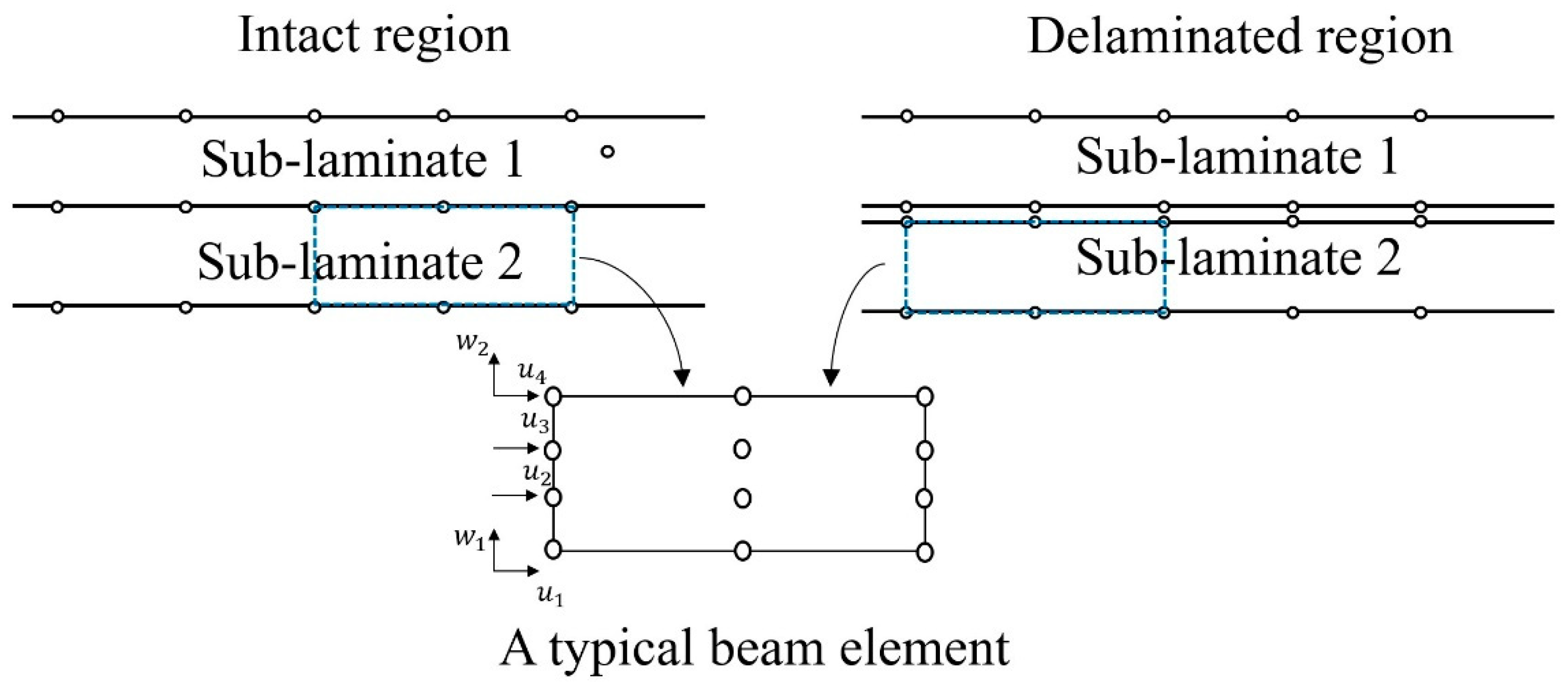
The utilization of the surface displacements in HOM provides ease in modeling delamination, which is shown in Figure 3. For the contact region, the adjunct sub-laminate/element is directly connected in the thickness direction by taking the nodes at the bottom surface of the upper sub-laminate and nodes at the top surface of the lower sub-laminate as common nodes. As for the delaminated region, these common nodes are separated into two sets of nodes without physical gaps so that the continuity of displacements is relaxed in this region. The figure also presents a typical beam element, where unknowns are taken at four reference planes; thus, four nodes are taken along the thickness direction. This model was implemented by developing a beam element where 3 nodes are taken along the axial direction. It should be noted that the 2D strain was decoupled into x (axial) and z (thickness direction) separately (see Equations (4)–(6)). Thus, the finite element interpolation was only applied to the one-dimension strain ε ¯ in terms of x (see Equations (6)–(8)). The integration along z direction was separately performed by using Gauss quadrature integration (see Equations (18) and (19)).
The above formulation was implemented by developing a code using MATLAB, which was employed to analyze intact/delaminated composite and sandwich beams having various configurations.

3. Numerical Examples for Validation

3.1. Intact Laminated Composite Beams

Simply supported intact laminated composite beams under a sinusoidal distributed load ( q = q 0 s i n ( π x / l ) where l is the beam length, and q0 is the load intensity) were first analyzed to show the performance of the proposed model in analyzing both symmetric (0/90/90/0) and asymmetric (0/90/0/90) composite beams. There were three aspect ratios ( S = l / h where h represents beam depth). Different sub-laminated schemes were used to model those beams, which were represented in terms of the total number of sub-laminates (n) by present (NSn). A convergence study showed the model requires 20 elements in the beam axis to produce stable converged predictions of displacements and stresses. Therefore, the results in this section and other examples were calculated by using at least 20 elements along beam length. These beams were made by four equal-thickness composite plies whose material properties along the fiber orientation were as follows: E1/E2 = 25.0, E2 = E3, G12 = G13 = 0.5E2, G23 = 0.2E2, and ν12 = ν23 = ν13 = 0.25. In addition, separate MATLAB (R2020a, MathWorks, New York, USA) codes were developed based on Pagano’s exact solution [49] and Reddy’s higher-order analytical model [11], which were used for validation.
Table 1 presents the mid-span transverse displacements (w) predicted at the mid-plane by the present mode with three sub-lamination schemes and the analytical models [11,49]. All the results in this table are expressed in their non-dimensional form ( w ¯ = 100 E 2 h 3 w / l 4 q 0 ) . They show that the deflection was significantly underestimated by the single-layer-based models for beams with S = 5 (i.e., thick beams). However, the present model NS1 (using one sub-laminate for modeling) had a relatively better performance compared to Reddy’s equivalent single-layer model [11]. In addition, the capability of sub-lamination modeling of the proposed model provided good flexibility to users, with a tradeoff between solution accuracy and computational efficiency. To study the performance of the present model in predicting stresses of laminated composites, the mid-span non-dimensional bending stresses ( σ ¯ x x = σ x x / q 0 ) at the beam’s top surface and the non-dimensional mid-plane transverse shear stresses ( τ ¯ x z = τ x z / q 0 ) at the beam’s end (left) are shown in Table 2. The stresses were predicted in these locations because they were expected to be high there. In addition, the elastic exact solution [48] and results produced by Reddy’s model [11] are also included in the table. Moreover, the through-thickness variations of σ ¯ x x , and τ ¯ x z predicted by different models at the mid-span of the symmetrical composite beam are plotted in Figure 4. It should be noted that all transverse shear stresses were calculated directly from the constitutive relationship. A similar performance found in calculating displacements could also be observed for the prediction of stresses from Table 2 and Figure 4. Although modeling the four-layer composite beam with two sub-laminates had a large deviation for calculating the mid-plane transverse shear stresses through a constitutive relationship, it still provided good predictions for bending stresses. Figure 4 also shows that the zero transverse shear stresses conditions and interlaminar continuity of transverse shear stresses were fulfilled when four sub-laminates were used. Thus, the sub-lamination scheme S2 is a good option for balancing the accuracy and computational cost unless an accurate prediction of transverse shear stress is needed.

3.2. Intact Laminated Sandwich Beams

A simply supported five-layer sandwich beam (0/90/C/90/0) was analyzed by the proposed model. Two different load cases applied on the beam’s top surface were considered: (1) localized load applied at beam mid-span (i.e., point load q = P), and (2) a load that was uniformly distributed ( q = q 0 ) along the x-axis. The stiff composite layers used as face sheets, and the properties along their fiber direction were as follows: E1 = 25.0E, E2 = E3 = E, G12 = G13 = 0.5E, G23 = 0.2E, and ν12 = ν13 = ν23 = 0.25. The material properties of the soft-core layer were E1=4.0E, E2=E3=0.05E, G13=0.06E, and ν12 = ν23 = ν13 = 0.25. The composite face sheets had a small distribution in material properties since the thickness of each of them was 0.1h, while that of the core layer was 0.8 h. Similarly, Pagano’s exact solution [49] and Reddy’s equivalent single-layer higher-order model [11] were also employed to analyze the same sandwich beam for the validation of the proposed HOM.
Table 3 shows the mid-span deflection calculated by the above models at the beam’s top surface (z = h/2), bottom surface (z = −h/2), and mid-plane (z = 0) for both loads. Different aspect ratios (S) were taken (S = 5, 20, and 50) for this simulation. The deflection (w) of the beam is expressed in non-dimensional form as w ¯ = 100 E 2 h 3 w / l 3 P for the point load, while this is the same expression as used in the previous example (Section 3.1) for the uniformly distributed load. It can be observed from Table 3 that the mid-span transverse displacement under the point load was significantly underestimated by Reddy’s model [11], especially for the thickest beam (S = 5). Due to the absence of through-thickness variation of transverse displacement in Reddy’s model [11], this deviation was most significant (more than 38%) at the surface where the load was applied (top surface). And it can be expected that with the increasing aspect ratio and the loading of a less localized force, this difference would have gradually diminished. A similar problem can also be observed in the present model when the whole beam was modeled with one sub-laminate (NS1). However, the introduction of variation for deflection over the thickness helped the present model (NS1), providing an improved prediction compared to the higher-order model of Reddy [11]. For the transverse displacement predicted at the beam’s top surface with S = 5 (the worst case), the error of the present model (NS1) was approximately 19.7% (corresponding to Pagano’s solution [49]), which was 38.7% for Reddy’s results [11]. In order to improve the performance of the present model, two different sub-lamination schemes of the present model were also employed to model the sandwich beam: (a) NS4, where two sub-laminates were used for the thick core layer and every two composite plies were modeled by one sub-laminate; and (b) NS6, where each physical composite ply was simulated by one sub-laminate, and the thick-core was simulated by two sub-laminates. Table 3 presents that NS4 and NS6 have evident benefits in improving the accuracy of the present model for most cases. Moreover, the results calculated by using these sub-laminate schemes showed good agreement with the exact solution [48], with errors of 0.33% (NS4) and 0.84% (NS6) for the worst case mentioned before. Moreover, the predictions of NS6 showed a minor improvement compared to the results of NS4, and this was expected since the soft-core layer has a much more prominent contribution of material prosperity than the composite sheets along the thickness direction. Thus, the sub-laminate S4 should be an optimum option in this scenario considering its better computational efficiency.

3.3. Laminated Composite Beam Contating Delamiantion

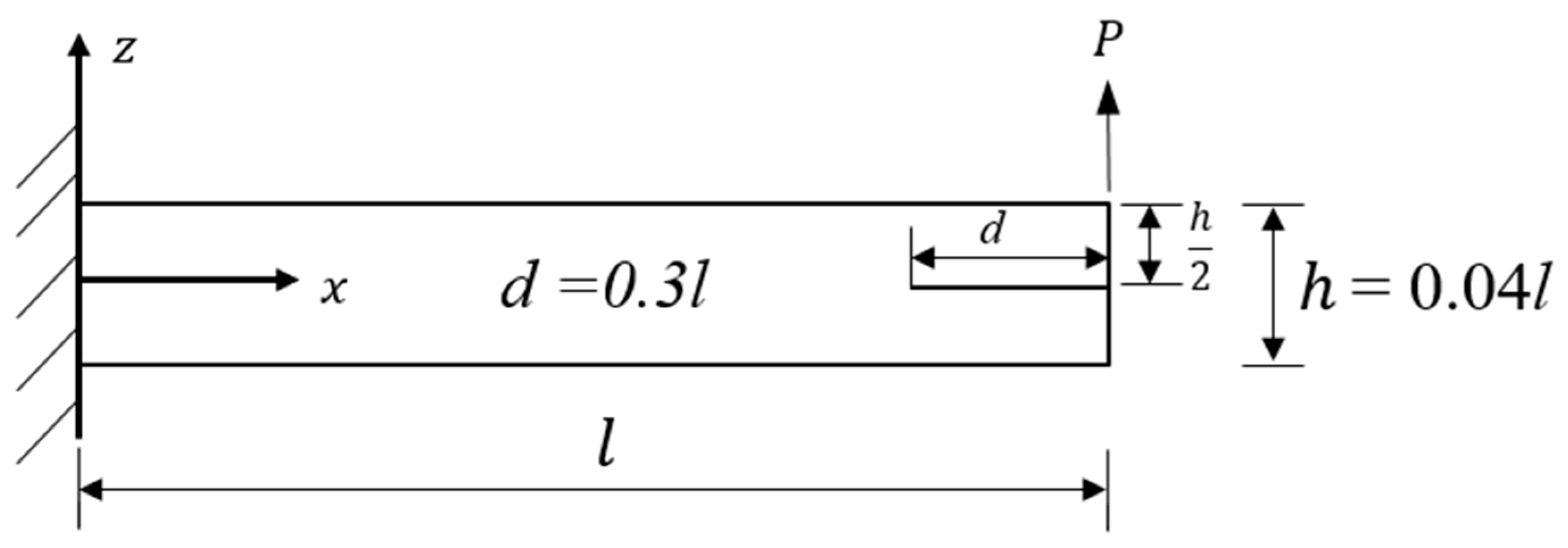
A composite beam with a delamination was analyzed to assess the performance of the HOM-based model in simulating delamination. A delaminated symmetrical layered composite beam [0/90/0/90]s was considered. One end of the beam was fixed, and a mid-plane delamination was inserted at the other end where a point load was acting on the beam top (see Figure 5). The same material properties utilized for the equal-thickness plies in Section 3.1 were also used in this section.
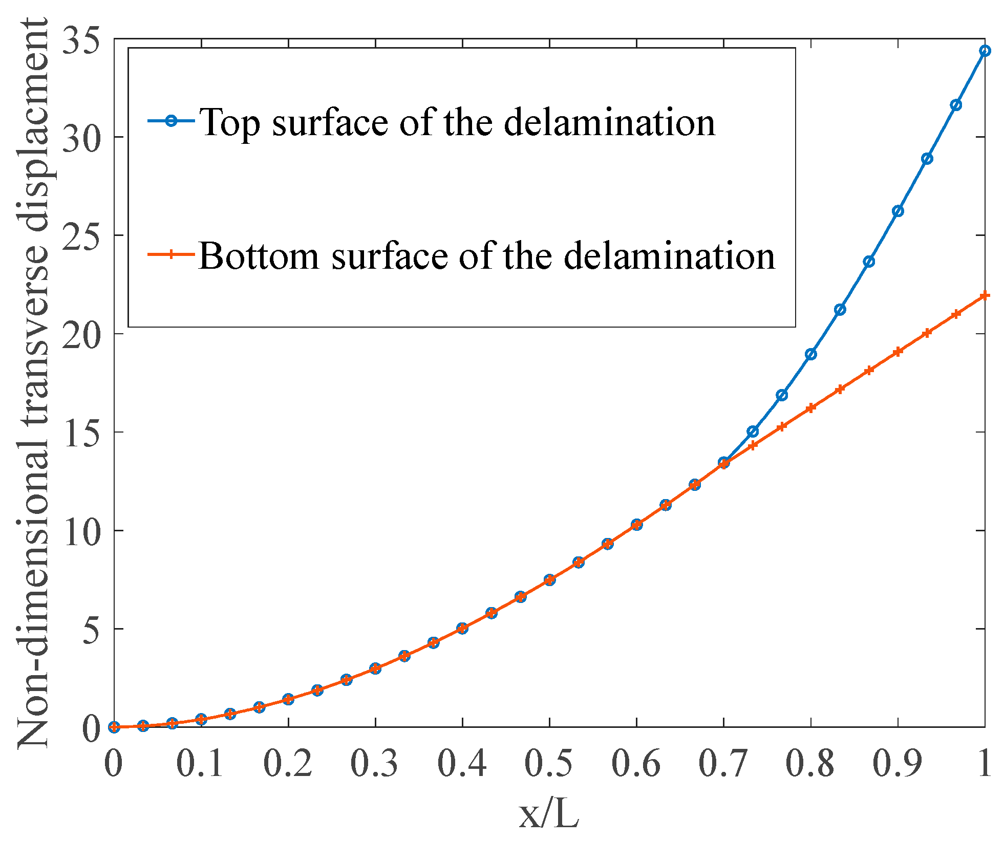
The present model with three sub-lamination schemes (NS2,NS4,NS8) was used to simulate the beam and the results are shown in Table 4. This table presents transverse displacements (w) and axial displacements (u) ( u ¯ = 100 E 2 h 3 u / l 3 P ) predicted at four different points: 1, beam top; 2, surface above the delamination; 3, surface below the delamination; and 4, beam bottom at the beam free end. Equations w ¯ = 100 E 2 h 3 w / l 3 P and u ¯ = 100 E 2 h 3 u / l 3 P were used to nondimensionalize these results. The value in this table shows that the surface above the delamination had a larger deflection than that below the delamination, which is an indicator of the opening of the delamination. For better visualization, the through-beam length variation of deflection at two sides of the delamination was predicted and plotted in Figure 6.
Since suitable results available in the literature are not adequate to validate the results of delaminated beams, a reliable commercial finite element package ABAQUS(Version 6.14, DASSAULT SYSTEMS, Paris, French) was employed to develop a detailed FE model for the validation. To accommodate the delamination by using the proposed model, at least two sub-laminates were needed. NS8, which provides the highest accuracy, was also used for modeling in addition to an intermediate option, NS4.
It can be observed from Table 4 that NS2 was adequate to simulate the delaminated composite beam in most cases.

4. Conclusions

This study presented a higher-order model that incorporates the concept of sub-lamination for the static analysis of intact and delaminated composite and sandwich beams. By taking displacement components at the beam top, bottom, and two internal planes, the proposed model achieved a cubic variation for axial displacement and linear variation for transverse displacement through the thickness. The presence of surface displacement parameters showed a significant benefit in modeling multilayered structures owing to the ease in connection of several sub-laminates in the thickness direction of the structure. The model was implemented by developing a pure displacement-based C0 beam element with three nodes. It was validated by analyzing different intact or delaminated composite and sandwich beams and comparing the results with existing solutions and results produced by a commercial finite element program. The following conclusions were made based on the numerical results.
  • The present model shows encouraging performance in analyzing multilayered structures subjected to different types of static loading. The incorporation of transverse displacement variation was beneficial in modeling the sandwich beams, especially subjected to localized load (e.g., point load). The proposed model also showed a good estimation for transverse shear stresses, which were calculated directly from the constitutive relationship. Moreover, modeling the whole structure with a single sub-laminate showed a better performance than the typical higher-order model with the equivalent single-layer hypothesis.
  • The model provides ease in the simulation of delamination by inserting it between two sub-laminates. The numerical results also showed that the model has adequate accuracy in analyzing delaminated composite beams.
  • The HOM-based model has high flexibility to choose the level of detail in the variation of displacement through the thickness for the modeling of multilayer composite and sandwich beams with or without delamination by choosing an appropriate sub-lamination scheme. Therefore, users can balance computational efficiency and prediction accuracy.

Author Contributions

Conceptualization, A.H.S. and Y.F.; methodology, A.H.S., Y.F. and G.L.; software, Y.F. and G.L.; validation, Y.F., A.H.S. and G.L.; formal analysis, Y.F. and G.L.; investigation, Y.F.; writing—original draft preparation, Y.F.; writing—review and editing, A.H.S. and G.L.; supervision, A.H.S. All authors have read and agreed to the published version of the manuscript.

Funding

The research received no external funding.

Data Availability Statement

Data used in this research can be available from the lead author by e-mail (Yuan Feng).

Conflicts of Interest

Guanzhen Li is an employee of the Sinosteel Wuhan Safety & Environmental Protection Research Institute. The paper reflects the views of the scientists and not the company.

References

  1. Doughett, A.; Asnarez, P. Composite Laminates: Properties, Performance and Applications; Nova Science Publishers, Incorporated: Hauppauge, NY, USA, 2010. [Google Scholar]
  2. Reddy, J. An evaluation of equivalent-single-layer and layerwise theories of composite laminates. Compos. Struct. 1993, 25, 21–35. [Google Scholar] [CrossRef]
  3. Kreja, I. A literature review on computational models for laminated composite and sandwich panels. Open Eng. 2011, 1, 59–80. [Google Scholar] [CrossRef]
  4. Maji, A.; Mahato, P.K. Development and applications of shear deformation theories for laminated composite plates: An overview. J. Thermoplast. Compos. Mater. 2022, 35, 2576–2619. [Google Scholar] [CrossRef]
  5. Li, D. Layerwise theories of laminated composite structures and their applications: A review. Arch. Comput. Methods Eng. 2021, 28, 577–600. [Google Scholar] [CrossRef]
  6. Fan, H.; Widera, G. Refined engineering beam theory based on the asymptotic expansion approach. AIAA J. 1991, 29, 444–449. [Google Scholar] [CrossRef]
  7. Mechab, I.; Tounsi, A.; Benatta, M. Deformation of short composite beam using refined theories. J. Math. Anal. Appl. 2008, 346, 468–479. [Google Scholar] [CrossRef]
  8. Thai, H.-T.; Choi, D.-H. A simple first-order shear deformation theory for laminated composite plates. Compos. Struct. 2013, 106, 754–763. [Google Scholar] [CrossRef]
  9. Amir, S.; Khorasani, M.; BabaAkbar-Zarei, H. Buckling analysis of nanocomposite sandwich plates with piezoelectric face sheets based on flexoelectricity and first-order shear deformation theory. J. Sandw. Struct. Mater. 2020, 22, 2186–2209. [Google Scholar] [CrossRef]
  10. Whitney, J.; Sun, C. A higher order theory for extensional motion of laminated composites. J. Sound Vib. 1973, 30, 85–97. [Google Scholar] [CrossRef]
  11. Reddy, J.N. A Simple Higher-Order Theory for Laminated Composite Plates. J. Appl. Mech. 1984, 51, 745–752. [Google Scholar] [CrossRef]
  12. Matsunaga, H. Interlaminar stress analysis of laminated composite beams according to global higher-order deformation theories. Compos. Struct. 2002, 55, 105–114. [Google Scholar] [CrossRef]
  13. Vidal, P.; Polit, O. A family of sinus finite elements for the analysis of rectangular laminated beams. Compos. Struct. 2008, 84, 56–72. [Google Scholar] [CrossRef]
  14. Pawar, E.G.; Banerjee, S.; Desai, Y.M. Stress analysis of laminated composite and sandwich beams using a novel shear and normal deformation theory. Lat. Am. J. Solids Struct. 2015, 12, 1340–1361. [Google Scholar] [CrossRef]
  15. Sayyad, A.S.; Ghugal, Y.M. Static and free vibration analysis of laminated composite and sandwich spherical shells using a generalized higher-order shell theory. Compos. Struct. 2019, 219, 129–146. [Google Scholar] [CrossRef]
  16. Whitney, J.M. Shear Correction Factors for Orthotropic Laminates under Static Load. J. Appl. Mech. 1973, 40, 302–304. [Google Scholar] [CrossRef]
  17. Reddy, J. A generalization of two-dimensional theories of laminated composite plates. Commun. Appl. Numer. Methods 1987, 3, 173–180. [Google Scholar] [CrossRef]
  18. Shimpi, R.; Ghugal, Y. A layerwise trigonometric shear deformation theory for two layered cross-ply laminated beams. J. Reinf. Plast. Compos. 1999, 18, 1516–1543. [Google Scholar] [CrossRef]
  19. Setoodeh, A.R.; Karami, G. Static, free vibration and buckling analysis of anisotropic thick laminated composite plates on distributed and point elastic supports using a 3-D layer-wise FEM. Eng. Struct. 2004, 26, 211–220. [Google Scholar] [CrossRef]
  20. Afshin, M.; Taheri-Behrooz, F. Interlaminar stresses of laminated composite beams resting on elastic foundation subjected to transverse loading. Comput. Mater. Sci. 2015, 96, 439–447. [Google Scholar] [CrossRef]
  21. Van Do, V.N.; Lee, C.-H. Isogeometric layerwise formulation for bending and free vibration analysis of laminated composite plates. Acta Mech. 2021, 232, 1329–1351. [Google Scholar] [CrossRef]
  22. Averill, R.C. Static and dynamic response of moderately thick laminated beams with damage. Compos. Eng. 1994, 4, 381–395. [Google Scholar] [CrossRef]
  23. Kapuria, S.; Dumir, P.; Ahmed, A. An efficient higher order zigzag theory for composite and sandwich beams subjected to thermal loading. Int. J. Solids Struct. 2003, 40, 6613–6631. [Google Scholar] [CrossRef]
  24. Vidal, P.; Polit, O. A sine finite element using a zig-zag function for the analysis of laminated composite beams. Compos. Part B Eng. 2011, 42, 1671–1682. [Google Scholar] [CrossRef]
  25. Nallim, L.G.; Oller, S.; Oñate, E.; Flores, F.G. A hierarchical finite element for composite laminated beams using a refined zigzag theory. Compos. Struct. 2017, 163, 168–184. [Google Scholar] [CrossRef]
  26. Abrate, S.; Di Sciuva, M. 1.16 Multilayer Models for Composite and Sandwich Structures. In Comprehensive Composite Materials II; Beaumont, P.W.R., Zweben, C.H., Eds.; Elsevier: Oxford, UK, 2018; pp. 399–425. [Google Scholar]
  27. Dorduncu, M. Stress analysis of laminated composite beams using refined zigzag theory and peridynamic differential operator. Compos. Struct. 2019, 218, 193–203. [Google Scholar] [CrossRef]
  28. Chakrabarti, A.; Sheikh, A. Vibration of laminate-faced sandwich plate by a new refined element. J. Aerosp. Eng. 2004, 17, 123–134. [Google Scholar] [CrossRef]
  29. Chakrabarti, A.; Sheikh, A. Behavior of laminated sandwich plates having interfacial imperfections by a new refined element. Comput. Mech. 2004, 34, 87–98. [Google Scholar] [CrossRef]
  30. Tessler, A.; Di Sciuva, M.; Gherlone, M. Refinement of Timoshenko Beam Theory for Composite and Sandwich Beams Using Zigzag Kinematics; NASA Technical Reports Server (NTRS): Washington, DC, USA, 2007. [Google Scholar]
  31. Pandit, M.K.; Sheikh, A.H.; Singh, B.N. An improved higher order zigzag theory for the static analysis of laminated sandwich plate with soft core. Finite Elem. Anal. Des. 2008, 44, 602–610. [Google Scholar] [CrossRef]
  32. Chakrabarti, A.; Chalak, H.; Iqbal, M.A.; Sheikh, A.H. A new FE model based on higher order zigzag theory for the analysis of laminated sandwich beam with soft core. Compos. Struct. 2011, 93, 271–279. [Google Scholar] [CrossRef]
  33. Chalak, H.D.; Chakrabarti, A.; Iqbal, M.A.; Hamid Sheikh, A. An improved C0 FE model for the analysis of laminated sandwich plate with soft core. Finite Elem. Anal. Des. 2012, 56, 20–31. [Google Scholar] [CrossRef]
  34. Chalak, H.D.; Chakrabarti, A.; Sheikh, A.H.; Iqbal, M.A. C0 FE model based on HOZT for the analysis of laminated soft core skew sandwich plates: Bending and vibration. Appl. Math. Model. 2014, 38, 1211–1223. [Google Scholar] [CrossRef]
  35. Soldatos, K.; Timarci, T. A unified formulation of laminated composite, shear deformable, five-degrees-of-freedom cylindrical shell theories. Compos. Struct. 1993, 25, 165–171. [Google Scholar] [CrossRef]
  36. Carrera, E. Theories and finite elements for multilayered plates and shells: A unified compact formulation with numerical assessment and benchmarking. Arch. Comput. Methods Eng. 2003, 10, 215–296. [Google Scholar] [CrossRef]
  37. Demasi, L. ∞3 Hierarchy plate theories for thick and thin composite plates: The generalized unified formulation. Compos. Struct. 2008, 84, 256–270. [Google Scholar] [CrossRef]
  38. Ferreira, A.; Araújo, A.; Neves, A.; Rodrigues, J.; Carrera, E.; Cinefra, M.; Soares, C.M. A finite element model using a unified formulation for the analysis of viscoelastic sandwich laminates. Compos. Part B Eng. 2013, 45, 1258–1264. [Google Scholar] [CrossRef]
  39. Bharati, R.B.; Filippi, M.; Mahato, P.K.; Carrera, E. Flutter analysis of laminated composite structures using Carrera Unified Formulation. Compos. Struct. 2020, 253, 112759. [Google Scholar] [CrossRef]
  40. Lee, J.; Gurdal, Z.; Griffin, O.H., Jr. Layer-wise approach for the bifurcation problem in laminated composites with delaminations. AIAA J. 1993, 31, 331–338. [Google Scholar] [CrossRef]
  41. Na, W.J.; Reddy, J. Delamination in cross-ply laminated beams using the layerwise theory. Asian J. Civ. Eng. Build. Hous. 2009, 10, 451–480. [Google Scholar]
  42. Chrysochoidis, N.; Saravanos, D. Layerwise dynamic response models for delamination composite beams with active piezoelectric sensors. In Proceedings of the 46th AIAA/ASME/ASCE/AHS/ASC Structures, Structural Dynamics and Materials Conference, Austin, TX, USA, 18–21 April 2005; p. 2186. [Google Scholar]
  43. Kharghani, N.; Guedes Soares, C. Influence of different parameters on the deflection of composite laminates containing through-the-width delamination using Layerwise HSDT. Compos. Struct. 2015, 132, 341–349. [Google Scholar] [CrossRef]
  44. Siorikis, D.; Rekatsinas, C.; Chrysochoidis, N.; Saravanos, D. An extended layerwise spectral finite element framework for delamination growth simulation in laminated composite strips. Compos. Struct. 2021, 276, 114452. [Google Scholar] [CrossRef]
  45. Cho, Y.; Averill, R. First-order zig-zag sublaminate plate theory and finite element model for laminated composite and sandwich panels. Compos. Struct. 2000, 50, 1–15. [Google Scholar] [CrossRef]
  46. Pai, P.F.; Palazotto, A.N. Two-dimensional sublamination theory for analysis of functionally graded plates. J. Sound Vib. 2007, 308, 164–189. [Google Scholar]
  47. Williams, T.O. A new, unified, theoretical framework for the formulation of general, nonlinear, single-scale shell theories. Compos. Struct. 2014, 107, 544–558. [Google Scholar] [CrossRef]
  48. d’Ottavio, M.; Dozio, L.; Vescovini, R.; Polit, O. Bending analysis of composite laminated and sandwich structures using sublaminate variable-kinematic Ritz models. Compos. Struct. 2016, 155, 45–62. [Google Scholar] [CrossRef]
  49. Pagano, N. Exact solutions for composite laminates in cylindrical bending. J. Compos. Mater. 1969, 3, 398–411. [Google Scholar] [CrossRef]
  50. Fish, J.; Belytschko, T. A First Course in Finite Elements; John Wiley & Sons: Hoboken, NJ, USA, 2007; Volume 1. [Google Scholar]
  51. Reddy, J.N. Mechanics of Laminated Composite Plates and Shells: Theory and Analysis; CRC Press: Boca Raton, FL, USA, 2003. [Google Scholar]
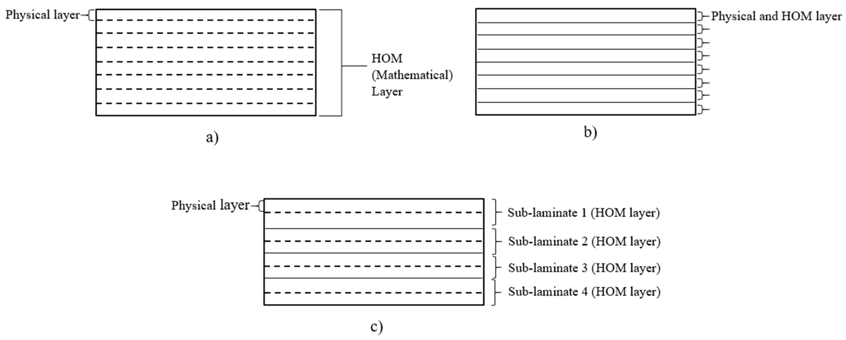
Figure 1. (a) One-layer model; (b) layer-wise like model; (c) sub-laminate model.
Jcs 08 00175 g001
Figure 2. Higher-order model (HOM)-based sub-laminate.
Jcs 08 00175 g002
Figure 3. Modeling of delaminated region.
Jcs 08 00175 g003
Figure 4. Through-thickness variation of (a) σ ¯ x x , and (b) τ ¯ x z for the symmetrical composite beams predicted at the beam midspan by different models [11,49].
Jcs 08 00175 g004
Figure 5. A cantilever laminated beam [0/90/0/90]s with single delamination under a point load.
Jcs 08 00175 g005
Figure 6. Variation of transverse displacement captured at surfaces above and below the delamination.
Jcs 08 00175 g006
Table 1. Non-dimensional middle-plane deflection ( w ¯ ) at mid-span for simply supported symmetrical and antisymmetric intact composite beams under sinusoidal load.
Lamination SchemeSourceS = 5% Error 1S = 20% ErrorS = 50% Error
0/90/90/0Present (NS1)2.29493.940.67101.440.57640.52
Present (NS2)2.31033.290.67440.940.57800.24
Present (NS4)2.38840.030.68070.010.57930.02
Reddy [11]2.27644.710.66991.600.57760.31
Pagano [49]2.3890 0.6808 0.5794
0/90/0/90Present (NS1)2.729813.471.22373.171.13761.04
Present (NS2)3.07622.491.25620.591.14700.23
Present (NS4)3.15350.041.26330.031.14920.03
Reddy [11]2.558818.891.21843.581.14230.64
Pagano [49]3.1547 1.2637 1.1496
1 % error was calculated corresponding to the exact solution of Pagano [49].
Table 2. Non-dimensional bending stresses and transverse shear stresses of simply supported symmetrical composite beams under distributed transverse load.
SSource σ ¯ x x % Error τ ¯ x z % Error
5Present (NS1)26.541.231.8193.55
Present (NS2)26.431.642.25119.35
Present (NS4)26.810.221.8960.35
Reddy [11]24.947.181.7298.32
Pagano [49]26.87 1.8863.55
20Present (NS1)285.60.457.7045.72
Present (NS2)285.80.389.84820.52
Present (NS4)286.30.218.2150.54
Reddy [11]284.20.947.08913.13
Pagano [49]286.9 8.171
50Present (NS1)1732.20.3219.524.92
Present (NS2)1733.70.2324.9421.48
Present (NS4)1734.20.2020.831.46
Reddy [11]1735.00.1617.7513.54
Pagano [49]1737.7 20.534.92
Table 3. (a): Nondimensionalized deflection ( w ¯ ) at the mid-span of a simply supported sandwich beam under localized loading. (b) Nondimensionalized deflection ( w ¯ ) at the mid-span of a simply supported sandwich beam under uniformly distributed load.
SSourceBeam Bottom% ErrorBeam Top% ErrorMid-Plane% Error
(a)
5Pagano [49]15.653 23.395 17.13816.3
Reddy [11]14.3458.3614.34538.6814.3450.51
Present (NS1)15.6630.0618.78819.6917.2252.40
Present (NS4)15.4751.1423.3180.3316.7262.44
Present (NS6)15.5020.9623.5920.8417.72016.3
20Pagano [49]3.7467 3.8525 3.7717
Reddy [11]3.44648.023.446410.53.44648.62
Present (NS1)3.72020.713.76902.173.74460.72
Present (NS4)3.74320.093.86270.263.76390.21
Present (NS6)3.74460.063.86550.343.76510.17
50Pagano [49]2.9281 2.9331 2.9297
Reddy [11]2.81573.842.81574.002.81573.89
Present (NS1)2.91490.452.91790.522.91640.45
Present (NS4)2.92760.022.93500.062.92920.02
Present (NS6)2.92790.012.93530.082.92950.01
(b)
5Pagano [49]15.653 23.395 17.138
Reddy [11]14.3458.3614.34538.6814.34516.3
Present (NS1)15.6630.0618.78819.6917.2250.51
Present (NS4)15.4751.1423.3180.3316.7262.40
Present (NS6)15.5020.9623.5920.8416.7202.44
20Pagano [49]3.7467 3.8525 3.7717
Reddy [11]3.44648.023.446410.53.44648.62
Present (NS1)3.72020.713.76902.173.74460.72
Present (NS4)3.74320.093.86270.263.76390.21
Present (NS6)3.74460.063.86550.343.76510.17
50Pagano [49]2.9281 2.9331 2.9281
Reddy [11]2.81573.842.81574.002.81573.84
Present (NS1)2.91490.452.91790.522.91490.45
Present (NS4)2.92760.022.93500.062.92760.02
Present (NS6)2.92790.012.93530.082.92790.01
Table 4. Non-dimensional displacements obtained from different depths (z) of the free end of the cantilever laminated beam [0/90/0/90]s with single delamination.
zSources w ¯ u ¯
h/2Present (NS2)33.5010−0.9868
Present (NS4)33.9085−0.9959
Present (NS8) 34.0594−0.9988
FE model34.2010−1.0152
0 aPresent (NS2)33.48330.5994
Present (NS4)33.89200.6149
Present (NS8) 34.04040.6202
FE model34.13340.6236
0 bPresent (NS2)22.01730.0184
Present (NS4)21.96420.0227
Present (NS8) 21.99840.0222
FE model21.99500.0222
h/2Present (NS2)22.01730.5998
Present (NS4)21.96420.5970
Present (NS8) 21.99840.5969
FE model21.99500.5966
a surface above the delamination; b surface below the delamination.
Disclaimer/Publisher’s Note: The statements, opinions and data contained in all publications are solely those of the individual author(s) and contributor(s) and not of MDPI and/or the editor(s). MDPI and/or the editor(s) disclaim responsibility for any injury to people or property resulting from any ideas, methods, instructions or products referred to in the content.