QuietPlace: An Ultrasound-Based Proof of Location Protocol with Strong Identities
by
 , and
, and
Dimitrios Kounas
, 
Orfefs Voutyras
,
Georgios Palaiokrassas
,
Antonios Litke
* and
Theodora Varvarigou
School of Electrical and Computer Engineering, National Technical University of Athens, 15773 Athens, Greece
*
Author to whom correspondence should be addressed.
Appl. Syst. Innov. 2020, 3(2), 19; https://doi.org/10.3390/asi3020019
Submission received: 20 February 2020
/
Revised: 27 March 2020
/
Accepted: 1 April 2020
/
Published: 7 April 2020
(This article belongs to the Section Information Systems)
Abstract
:Location-based services are becoming extremely popular due to the widespread use of smartphones and other mobile and portable devices. These services mainly rely on the sincerity of users, who can spoof the location they report to them. For applications with higher security requirements, the user should be unable to report a location different than the real one. Proof of Location protocols provide a solution to secure localization by validating the device’s location with the help of nearby nodes. We propose QuietPlace, a novel protocol that is based on ultrasound and provides strong identities, proving the location of the owner of a device, without exposing though their identity. QuietPlace provides unforgeable proof that is able to resist to various attacks while respecting the users’ privacy. It can work regardless of certificate authority and location-based service and is able to support trust schemas that evaluate the participants’ behavior. We implement and validate the protocol for Android devices, showing that ultrasound-based profiles offer a better performance in terms of maximum receiving distance than audible profiles, and discuss its strengths and weaknesses, making suggestions about future work.
1. Introduction
Nowadays, more and more people carry their smartphones and other devices with them throughout the day. As they move from place to place, location-based services (LBS) take their location into consideration in order to influence their behavior. Although smart devices have the ability for accurate geolocation through Global Navigation Satellite Systems (GNSS) such as the Global Positioning System (GPS) and Galileo, Wi-Fi networks, and cell towers, the location reported to the services is not validated. When there is a benefit from being at a specific location, the incentive to cheat the location-based service is created. In [1,2] authors mention Trusted Platform Module, a tamper-resistant hardware component that makes spoofing the reported location impossible. However, this is not currently available in commercial devices and has additional cost. It is also useless if the device cannot obtain its location (i.e., due to jammed GNSS signals).
A proof of location (PoL) protocol is a system that assists devices in getting a digitally signed proof of their location, with the help of nearby entities. It can either provide both the localization and the validation [3] or just validate the device’s reported location obtained by other sensors [4,5]. PoL protocols could be used in cases where location validation is required, such as location-based access control [6], location-based content access, customer rewards [1], employee or merchandise tracking, etc. Electronic voting systems could also benefit from the assurance that the voters vote in the areas they live. On the one hand, recent works on PoL use fixed positioned sensors [7]. Vora et al. [8] use omni-directional or directional propagation of radio signals, where some sensors are placed such that they receive the signal from the prover if it is inside the protected area. On the other hand, other proposed approaches avoid the utilization of fixed sensors [9] as in the work of Rasori et al. [10], where the use of unmanned aerial vehicles (UAVs) is examined.
Davis et al. propose an electronic alibi system for use in court [11]. In cases where spoofing is not of big concern, such as social network applications, validating one’s location contributes to establishing trust in these networks and between users by securing the sincerity of the latter. PoL can be regarded as a technology specifically useful at network edge, as it makes it possible for the various location-aware services to associate users and devices to verifiable locations, while at the same time preserving the necessary level of privacy. At the same time, Internet of Things technologies, strongly coupled within a larger area of LBS [12], are aiming to offer services at the edge and can benefit from such PoL approaches. Limitations of GNNS—such as indoor localization, time overhead to acquire accurate coordinates, limitation for low powered IoT devices, etc.—reveal the need for additional localization services which can be provided through PoL techniques such as the one presented in the current paper.
The main contribution and innovation of the paper comprises the following. At first, we extensively present the characteristics of PoL protocols. We identify the difficulty of proving a person’s location (and not just of their device) and provide a solution. In the literature, this is referred to as strong identities [13]. A strong identity is a piece of information that identifies the user, is hard to forge and is bound to a PoL protocol session. We propose QuietPlace, a novel PoL protocol that is based on ultrasound and provides strong identities, proving the location of the owner of the device, without exposing though their identity. The strong identity requirement makes collusions between users impossible, even if the two devices share the same user’s credentials. This is the common vulnerability of protocols as detailed in the relevant literature. Finally, we implement the protocol for Android devices showing that ultrasound-based profiles offer a better performance in terms of maximum receiving distance (measured up to 235 cm) than audible profiles, and discuss its strengths and weaknesses, making suggestions about future work and possible improvements.
The rest of the paper is structured as follows: In Section 2, we identify the characteristics of PoL protocols. Then, in Section 3, we explain the meaning of strong identities and propose a high-level solution. In Section 4, the system model of our protocol is described, along with a summary of the exchanged messages. Section 5 presents the challenges that we had to tackle while designing our protocol. Afterwards, in Section 6, we extensively present the messages exchanged in QuietPlace. In Section 7, we provide a security and privacy analysis and describe how QuietPlace resists to man-in-the-middle attacks. In Section 8, we present a prototype implementation. Finally, Section 9 concludes the paper.
1.1. Definitions and Participating Entities
In the following we provide an overview of the terminology, definitions, and types of participating entities and attacks as they will be used throughout the paper.
- A ‘proof of location’ (PoL) is a digital certificate that validates a device’s location at a specific time. A proof of location may consist one or more location proof segments.
- A ‘location proof segment’ (LPS) is a piece of information that is produced by a device and validates or cancels the location claim of another device.
- The ‘participants’ are the devices that participate in the location proof system. Some participants (i.e., smartphones) can have many roles, while other (i.e., a certificate authority) can have only one. The participants are referred to via their role in the system. In our protocol, the roles of the participants are: prover, witness, certificate authority, and verifier. The ‘users’ are the human owners of the devices. The ‘prover’ is the device that wants to obtain a PoL certifying its existence at a particular place on a particular time. The ‘witness’ is a device near the prover that certifies that the prover is indeed in its proximity, when it receives a request from the prover. Witnesses may belong to users, something that makes them untrusted. They can also be owned by a verifier or a certificate authority (CA) and thus be trusted. The ‘verifier’ is the entity that the PoL created between the prover and the witnesses is addressed to. Usually, it is a location-based service. The ‘certificate authority’ (CA) is responsible for keeping a list of the participants in the system and validating their identities. It can also implement a trust schema by ranking the users according to their behavior.
- With the term ‘identity’, we refer to the unique identifier of each participant. This is expressed with the use of unique key pairs, related to a username by the CA. If a participating device belongs to a user (i.e., a prover or witness), the identity is linked to the user, who is registered with credentials (username/password) to the CA and the location-based service (verifier).
Proof of location protocols may utilize additional entities that are required for their operations. The proof of location server is used in some protocols such as [5]. It acts as an intermediate that receives proofs from provers and is responsible for transfering them to the verifiers. We do not consider a server in our protocol. In a typical PoL protocol, the prover collects LPSs from nearby witnesses that can be either decentralized nodes [4] (i.e., other users) or part of the infrastructure [14]. The witnesses may also provide the prover with a location [3]. The prover then creates the PoL and can present it either directly to the verifier or after the PoL is checked by another entity such as a CA or a server [5]. Other protocols such as [15] assume that the verifier is near the prover, acting as a witness that just verifies the prover’s location.
1.2. Malicious Users and Types of Attacks
There has been an extensive study on the vulnerabilities and attacks in a proof of location context [1,4,5,6,16]. Depending on the role, a malicious user has specific purposes which are detailed in the sequel.
- An ‘eavesdropper’ listens to the communication and aims to learn the identity or the location of the legitimate users.
- A ‘malicious prover’ aims to obtain a PoL for a location they have never been to or have been to at a different time. They collude with other witnesses or try to steal another prover’s PoL. They can also create fake witnesses, such as in the case of a Sybil attack [17].
- A ‘malicious verifier’ exposes the prover’s identity and/or location or tries to reuse their PoL.
- A ‘malicious witness’ may decline to cooperate with the prover, cancel valid claims or send no LPS, send an LPS validating an invalid location, send more than one LPS or try to obtain more information on the prover’s identity.
- A ‘malicious certificate authority’ does not perform validations correctly, favors some users, or tries to expose their identity.
Malicious users deploy various attacks by themselves or by colluding with others:
- In ‘distance fraud’, a malicious prover tries to convince a witness that they are closer than in reality. Proximity tests, which are described later, attempt to tackle this attack.
- In ‘mafia fraud’, a man-in-the-middle M carries the messages between a prover P and a witness W, to convince W that P is close to them. M appears as a witness to P and as a prover to W.
- In ‘distance hijacking’ attacks, a man-in-the-middle M tries to steal the session between P and W to obtain P’s LPSs.
- In ‘P-P collusion (terrorist fraud)’, a prover P1 in location X colludes with a prover P2 in location Y, so that P2 gathers LPSs from neighboring witnesses and creates a proof that presents P1 as being at location Y. The man-in-the-middle prover P2 may act as a simple relay or may possess P1′s credentials.
- In ‘W-W collusion’, witnesses collude to either validate an invalid claim by the prover, to invalidate a valid claim by the prover, or to not participate in the protocol execution at all.
- In ‘P-W collusion’, a prover cooperates with a witness to provide them with one or more LPSs for a false location.
As it becomes evident from the above, the main goals in PoL protocols are to provide unforgeable proofs that respect the users’ privacy and are also able to detect and tackle the above attacks.
2. Characteristics of PoL Protocols
PoL protocols have different characteristics depending on their purpose and design. Having many of the characteristics defined below does not necessarily make a protocol more secure or efficient. We describe below the main characteristics of PoL protocols, as these occur in the relevant literature. The specific characteristics have been the basis for the definition and direction of the current research effort as well.
- Proof creation architecture: Witnesses can either belong to users or be controlled by a centralized authority. In the first case, we have a peer-to-peer architecture and in the second a centralized one. The above approaches can be combined, resulting in a hybrid architecture.
- Proof verification architecture: The verification process between the prover and the verifier can be executed directly between the two parties or indirectly with the involvement of other entities.
- Use of a trusted third-party/certificate authority: Many proof of location protocols include a certificate authority (CA) in their system model. Depending on its duties, the CA may pose a single point of failure.
- Geocoding: The way location is represented. Examples include geographical coordinates, a geocoding system such as Plus codes [19], or arbitrary values (country, city, etc.).
- Geolocation: A proof of location protocol may provide a system for calculating the position of the nodes involved or, more commonly, just verify the location provided by other sources such as GPS.
- Proximity test: A procedure between prover and witness that certifies that they are close to each other.
- Incentive to participate: An incentive such as a cryptocurrency reward can be given to the users to continue providing resources (i.e., install witness nodes) to the system.
- Location granularity levels: The prover can choose the granularity in which their location is known to the verifier. For example, the prover can choose to reveal their exact coordinates or just provide the name of the city or country where their location belongs to.
- Verifier-agnostic proofs: The PoL produced during a protocol session can be verified by different verifiers. This characteristic is necessary to support proactive proofs of location, which are proofs that are produced by the prover without being asked to do so by a specific verifier. In this case, the prover does not know from the beginning to whom the specific proof should be addressed.
- Proof of location chains: The prover can create chains of proofs that are either tamper-proof or tamper-evident. By using chains, the verifier can track the location history of a prover. Different schemes have been proposed [2,9,20,21] and some of them allow the prover to hide information from a proof in the chain without being able to hide the existence of a proof completely.
3. A Proposal for Strong Identities
Most of the protocols in literature prove the location of the user’s device, but not of the user themselves. The user can still give their device to others or even login with their credentials on many devices. In cases where higher security standards are required—i.e., in a crime investigation—most protocols fail to provide a PoL for the user of the device, making the protocol useless.
PoL protocols rely on a procedure which inserts intermediates between the users. The intermediates are the devices that execute the protocol. However, although the devices belong to physical users, they must be with them at the time of the proof’s creation. As a result, to provide a complete PoL for the user of the device, three correlations must be made:
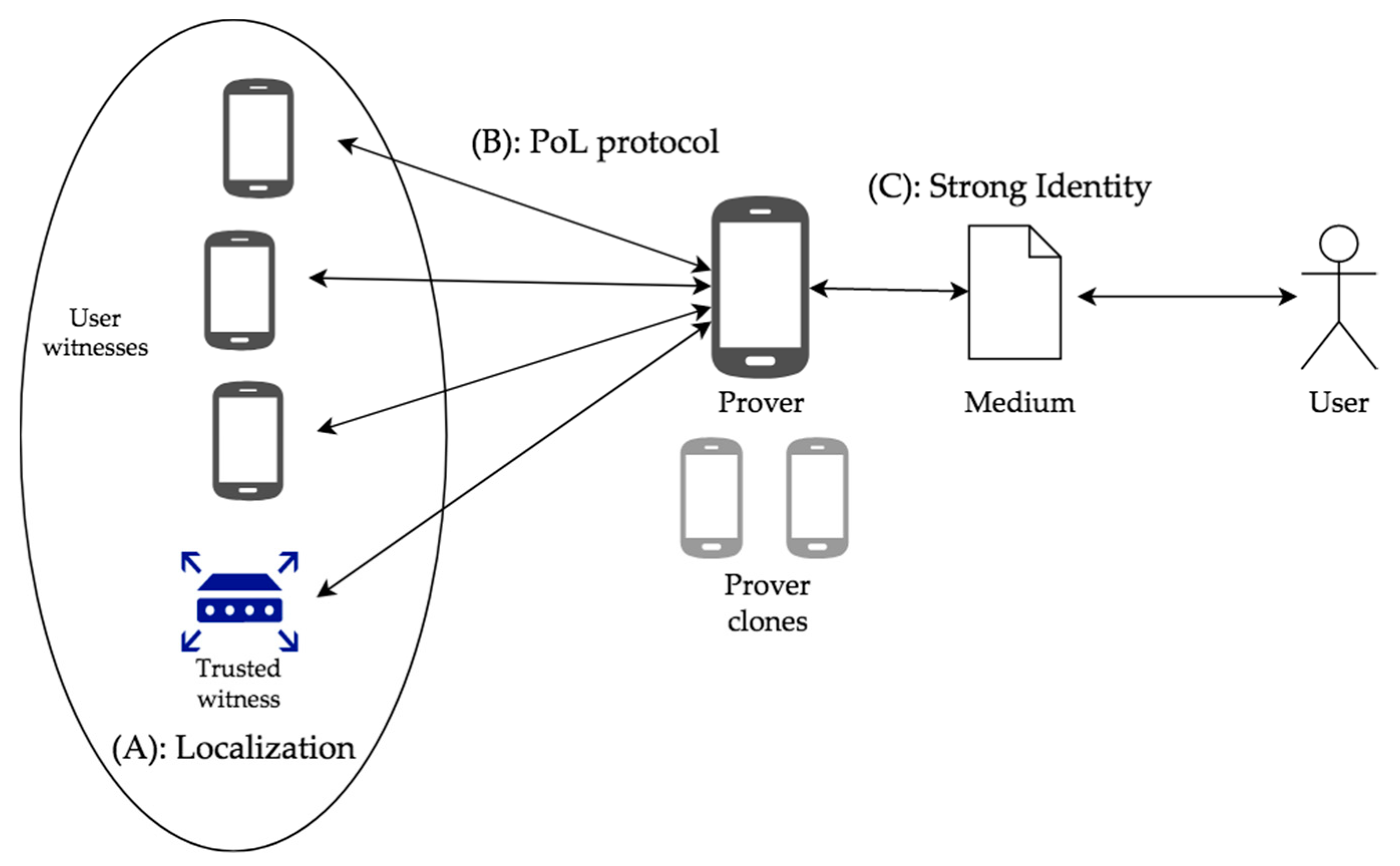
1. Correlation A relates the witnesses to a particular location. It is satisfied by either trusted devices with known location or by other users’ devices that determine their position using a localization method, such as GPS. The PoL protocol itself may provide an infrastructure and a mechanism for localization [3].
2. Correlation B relates the user’s device (prover) with the witnesses. It is satisfied by the PoL protocol executed between the prover and witnesses. The aim is to certify that the prover is near the witnesses at the specific time. Most PoL protocols in the bibliography make only this correlation. They certify that the device with the user’s credentials is in the vicinity of the witnesses. However, there can be many prover devices carrying the same user’s credentials. Thus, connection B does not bind the user to the location.
3. Correlation C relates the user with the device, at the specific time that the PoL protocol is executed. In order to satisfy this connection, a medium is produced by the prover during the protocol session. This medium certifies that the prover is at the user’s possession during the PoL creation. It is called ‘strong identity’, because it does not only certify the location of the device, but also the location of the user per se.
A PoL protocol may satisfy all of the above correlations. At the very least, it must satisfy B. The connections between the entities during the collection of LPSs are depicted in Figure 1.
In [13], strong identities are satisfied by exchanging a medium in a challenge-response schema between the witness and prover. We briefly discuss the authors’ proposals. In the simple case, the prover just sends a photo that includes the user of the device to the witness. However, this test is not sufficient on its own, since a malicious user can reuse an old saved photo of themselves. As such, the authors include a random number (nonce) in the procedure. The witness sends the nonce to the prover and then, the user must write this number on a piece of paper and send a photo that incudes themselves and the written number as a response to the witness. This method prevents using an old saved photo; however, a malicious user can still have a saved template of themselves (i.e., themselves holding a blank piece of paper) and add the required nonce by using photo manipulation software. Apart from using pictures, the authors investigate the possibility of using voice recordings as the identifying medium. They propose that the witness sends a unique sentence as a challenge to the prover. The user of the prover device must record themselves reading that sentence and send the recording back to the witness as a response. However, another’s voice that resembles the one of the legitimate user may be used, with or without editing. Also, the user can have saved prerecorded words in their device and let the device assemble the required sentence by using audio editing software. In the second case, the result would be probably very unnatural.
In all of the above scenarios, replay attacks should be taken into consideration. The legitimate user could create the strong identity information required by the witness and then pass it to a man-in-the-middle, who transmits it to the witness. The strong identity medium must therefore include elements that identify the user (i.e., a photo of themselves) and the session (i.e., the nonce). Methods that include a photo are easier to forge from a session perspective (i.e., change the nonce, use a saved photo) and methods that include a sound recording are easier to forge from a user identification perspective (i.e., people with similar voices).
We want to include as much information as possible about the user and the session and also make it very difficult and even impossible for a malicious user to forge the medium. We combine the advantages of the two mentioned approaches (image and sound) so we decide to use a video as the medium of our strong identity. To bind the user with the medium, we require that they appear in it. To bind the medium with the PoL protocol session, we require the user to speak out loudly a nonce sent by the witness. However, we would like to include the whole PoL protocol session in the video, so that there is no ambiguity that the video was indeed created near the witnesses at the specific time. In order to achieve this, we use ultrasound as the physical layer for communication between prover and witnesses. The resulting audio-video file contains the face of the user, who speaks out loud the random nonces that the witnesses send to the prover. Also, the messages exchanged between prover and witnesses can be heard in the background, as they are transmitted via ultrasound. As a result, a verifier will be able not only to be sure about the prover’s location, but also about the user.
At this point, it should be mentioned that recently, AI-synthesized face swapping videos—commonly known as the DeepFakes—have become an emerging problem. A machine learning based free software tool has made it easy to create believable face swaps in videos, leaving few traces of manipulation [22], and correspondingly, there is an increasing interest in developing algorithms that can detect them. However, it should be noted that in many LBS scenarios and applications, what is important is ensuring that a (and not ‘the’) human user holds a device that is close to an area of interest, while the identity of the user per se is not of much importance. While we recognize that DeepFakes can bypass the human user’s recognition per se, QuietPlace still ensures that a device asking for PoL and the corresponding user are indeed at the same place and the right place. Ensuring that the problem of DeepFakes is tackled is an interesting point of future research, which could extend the usage of QuietPlace to scenarios where the identity of the user per se would be required.
4. High Level System Description
We focus on the separation of knowledge between several entities in order to provide secure location proofs without compromising the users’ privacy. The CA learns only the identities of the users involved in a PoL session. It checks their digital signatures and may evaluate them according to its trust schema. The verifier learns only the identity of the prover and their location at the specific time, along with the trust information provided by the CA. In Figure 2, the entities participating in our protocol are depicted, along with the messages that they exchange during the protocol execution. It is important to understand that, in some cases, the CA and verifier role are assigned to the same physical entity. For example, if a hospital needs to check that a doctor is in their office in order to give them access to patient data, it can set trusted witnesses and perform both identity checking and location proof verification. In this case, the same entity has complete knowledge. However, it is up to the users to decide to which CA they sign up.
We describe the general idea of the communication between the users, before getting deeper into the exact content of the messages. We divide the whole procedure in two phases: a) the location proof creation, and b) the location proof verification.
Our protocol begins with the prover sending a Prover Request (PR) to the witnesses. This is a broadcast message addressed to any possible witness in the vicinity of the prover, containing the location that the prover claims to be at. Each witness willing to participate answers with a Witness Presence (WP) message. The prover starts recording a video, depicting the owner of the device using the front camera. The prover then initiates the procedure by sending a Start message. Next, a challenge-response procedure is executed between the prover and each witness. The purpose of this procedure is for the witnesses to verify that the prover is indeed in their vicinity, and does not use a man in the middle. Each witness sends a Challenge (C) and the prover has to quickly send a Response (R). In the challenge, a nonce is sent that is meant to be read out loud by the user. When the challenge-response procedure is completed with all witnesses, the prover stops video recording, calculates the hash of the video file, and sends it in a Video Hash (VH) message to the witnesses. After receiving the VH, each witness sends a Location Proof Segment (LPS) to the prover, containing a positive or negative answer to the prover’s claim. Each witness then sends a list with all the witnesses detected, as we will discuss in detail in the following section. At this point, the proof of location creation phase is complete. The whole phase is recorded on video by the prover, depicting the user and capturing the ultrasound messages being exchanged, something that supports the strong identity characteristic.
When the prover wants to verify its location, it combines the LPSs received from the witnesses in a Location Proof Assertion (LPA) message that is sent to the CA. The CA performs identity checks and evaluates the witnesses’ opinion, if a trust schema is being used. It keeps only the witnesses’ positive or negative answer, their reputation, and the location-relevant information and constructs the Verifier Segment (VS) message, sending it back to the prover. The prover then constructs the final Location Proof (LP) that contains (i) the verifier segment, (ii) the video captured during the creation phase and (iii) some auxiliary location-relevant information that sets the desired granularity level to be revealed. The prover sends the LP to the verifier, who will then decide whether it will be accepted or not.
5. Technical Challenges
In this section, we describe the challenges that have been faced while designing a protocol that aims to provide secure, privacy-preserving proofs of location that satisfy the need for strong identities. The challenges are identified in the three following categories:
1. Location: The way the participants’ location is described and the ability to disclose different location levels. Also, the techniques that are used to prove the proximity of nearby devices.
2. Security and Privacy: Includes the secure communication between participants and their ability to privately share information that will be revealed to the responsible validators.
3. Service Reliability: Being able to assess the participants according to the behavior and detect malicious ones.
5.1. Proximity Test
Witnesses need to assure that the prover is in their proximity, so they can provide the prover with a valid location proof segment (LPS). Proximity test is a core element of PoL protocols. In the literature, various techniques are being used, such as distance bounding. Distance bounding consists of a fast bit exchange between prover and witness [4,16]. Those bits are related to cryptographic data that identify the users involved without exposing their identities. These methods require high timekeeping precision, which is unavailable in consumer devices [6,23]. Another technique is beaconing [14]. Beacons with known locations emit signals that identify them. The prover captures those signals and presents them to prove that they were near specific beacons. Context-based proximity test [24,25] is another technique that makes use of environmental signal characteristics to estimate the prover’s location and thus deduce their proximity to the witness.
In our protocol, we decided to use a simple timeout-based proximity test as in [15] which was considered to be sufficient for tackling most of the corresponding security challenges as presented in Section 7 of the paper. During the challenge–response phase, the witness sends a message to the prover. This message contains a random number called a nonce. The prover has to respond back with this nonce. If they respond within a specific time, the witness assumes that they are close to each other. Everything is captured on video, so that the verifier can later make sure that the prover answered on time.
5.2. Geocoding
Geocoding has a double meaning. On the one hand, it refers to the computational process of transforming a physical address description (i.e., a street number in a city) to a spatial representation on the Earth’s surface (i.e., numerical coordinates) [26,27]. On the other hand, it refers to a geographic coordinate system, which assigns numbers, names, or other identifiers (i.e., alphanumerical sequences) to locations on Earth [28]. People mostly use addresses, while computers use coordinates to refer to locations. In our work, we use the second meaning of the term, which is also known as location encoding.
There are many geocoding systems available [23]. Their common feature is that they use identifiers to refer to either a point or an area on the earth’s surface. Others, such as geographical coordinates, also support referring to the height above surface. In the context of proofs of locations, we seek a geocode system that will use short, easy to remember identifiers that refer to areas and not points. In this way, it will be easier for nodes to deduct that they are close to each other, without the need of calculating the distance between them. We also require that the system supports gradation of the areas, with a corresponding change to the identifier, in a way that the subareas within an area have the same prefix as the area. In this way, it will be trivial to support location granularity levels by beginning from a small area and gradually removing the last characters until we reach a bigger one.
We decided to use Plus Codes [19], a free, open-source geocoding system that supports location granularity levels. Plus Codes have a full length of 10 or 11 characters. They are universally unique and refer to areas. First, the Earth is divided to a grid of 9 rows and 18 columns. Each area is 20 degrees by 20 degrees long and is further divided to a 20 × 20 grid up to 4 times, until areas become approximately 14 m × 14 m long. At this stage, the code has a length of 10 characters. A last division to a 5 × 4 grid results in areas of approximately 3 m × 3 m that are referred to with an 11-character code. Beginning with two characters in the first division, each time a subarea is chosen, two characters are added to the end of the code, except from the last stage where only the 11th character is added. In this way, we use the different grid levels as our granularity levels.
5.3. Location Granularity Levels
To support different location granularity levels, protocols in literature use mainly three techniques, with some variations. The first technique expresses the users’ location using a grid. The granularity levels are the subdivisions of this grid [24,25]. In the second one, multiple encryption, the prover encrypts all different location levels with a symmetric key and includes all of them in its proof [6]. Together with the proof, the prover sends the symmetric key that unlocks the desirable granularity level to the verifier. This technique produces proofs that are big in size, containing unnecessary information.
In QuietPlace we used the third technique, hash chains, to include all possible location granularity levels in the proof without redundant information. There are many different variations of hash chains used in proof of location protocols [1,2,4,16] all of which are compatible with our protocol. We used a simple hash chain as described in [24]. This chain can be constructed as shown in Figure 3.
We consider n different location levels, where L0 is the finest (highest accuracy) and Ln−1 the coarsest (lowest accuracy). The prover begins by calculating a random number, K0 (seed). If h() is a hash function, then the prover produces the chain K = Kn|Kn-1|…|K1|K0 where Ki + 1 = h(Li|Ki). We name Kn as the head of the location chain.
Witnesses receive the head Kn and the finest information L0, K0 from the prover. By consecutive hashing, they can recalculate the head of the chain and make sure that it is correct and include it in their LPSs. In the final proof to the verifier, the prover has to include only the head of the chain, Kn and the desirable granularity level Li along with the corresponding part of the chain Ki. Given this information, the verifier can reach the head of the chain, which has been validated as correct by the witnesses.
The CA is unable to obtain any location-relevant information included in any message, as it is described in Section 6.
5.4. User Identification and Secure Communication
Each user is identified by the credentials stored in and used by their device. To identify each device and verify that it is the source of a message asymmetric cryptography is usually being used. Each physical user has their credentials (i.e., an email or a username) that are used by their device as their identity along with one or more private/public key pairs associated with it. The device signs each message with its private key, producing a digital signature. The signature of a message m is the hash of the message encrypted using the private key. This signature can be verified later with the user’s public key. In our protocol, we use SHA-256 as our hashing function h() and the RSA asymmetric cryptosystem with a key-size of 1024 bits for signatures.
In most proof of location protocols, the entity responsible for managing the entities that participate in the system is the certificate authority (CA), who can also perform signature verification. Other protocols like [3,18] use a blockchain. The identity of the devices and the validity of the information that they submit is checked by distributed nodes that come to a consensus. It is also possible that each node self-signs their messages. This means that there is no CA responsible for associating its keys with its identity and performing signature validation [14]. The other nodes with which it communicates decide whether they will trust it or not.
The asymmetric cryptosystem is suitable for signature verification, as only the hash of the message has to be encrypted. However, it has a limit in the amount of data it can encrypt, making it unsuitable for longer message encryption [25]. Thus, for the secure encrypted communication between the nodes, we use symmetric key encryption. The sender A generates a random symmetric key k and encrypts the message m with that, producing the encrypted message k(m). It also encrypts k with his private key pA, producing pA(k). It sends the two encrypted information k(m)|pA(k) to the receiver B. The receiver decrypts the symmetric key k using A’s public key PA. Finally, it uses k to decrypt the message m. For symmetric encryption, we use the AES algorithm.
5.5. Selective Information Hiding
Knowing the identity of the participants and as a result of the users taking part in a PoL protocol session may compromise their privacy. Especially in QuietPlace, where the whole session is recorded and later sent to the verifier, it is important that no identity-related information is leaked during the proof creation phase.
In the literature, several techniques are proposed to hide the users’ identity and signature, so that they do not appear in cleartext. In [5,21] every user has several pseudonyms that can be used in their messages. The CA is responsible for matching the pseudonyms with the real identity. A widely used technique are cryptographic commitments [29,30]. A piece of information is temporarily hidden with the purpose of being revealed later. The procedure consists of two stages. In the first stage (commitment) the sender ‘locks’ a sensitive information and sends it to the receiver. In the second stage (decommitment), the sender sends the key to the receiver, who can now access the locked information.
A simple commitment scheme uses a hash function h() [20]. In the commitment stage, the sender wants to commit to a message m. The sender produces a random number r and calculates the commitment C = h(m|r). Then, the sender sends C to the receiver. In the decommitment stage, the sender sends m and r to the receiver. The receiver recalculates the hash C’ = h(m|r). By comparing C with C’, the receiver can verify that the contents of the initial commitment were indeed m and r.
An even simpler commitment-like technique is including the hash of the identity or the signature in the messages. This information cannot be understood in the first place, but when the sender of the message wants to reveal their identity, they can just send the actual information to the receiver, who can verify it by hashing and comparing with the hash initially received. Group signatures are used in [4,20] to hide the identity of the witnesses. Each witness signs each of their message with a unique private key, but their signature is verified with a group public key. This way, the signer’s identity is hidden, but the fact that they belong to a specific group (in this case the witness group) can be verified.
In QuietPlace we use simple commitments as described above to protect the identities of the prover and witnesses. However, any other commitment scheme is compatible. For hiding the signatures, we require that they are hashed. Only the CA receives the signatures in encrypted messages to perform verification.
5.6. Witness Swarm Integrity
It is very important that the PoL created by the prover (in case of QuietPlace it is the LPA message) contains all the LPSs received from all witnesses, regardless of whether they confirmed or rejected the prover’s assertion. Even if the witness identity and the answer it gives is hidden, the prover can still learn if an LPS comes from a colluding witness via a private communication link. The prover could then include only the LPSs from the colluding sources, creating a fake proof.
In [25], the authors propose that the nodes (in their case provers) include in their messages a list of all the other nodes that they see in their vicinity. In this way, a server can create a graph relating the nodes that saw each other, detecting nodes that are hiding themselves. Inspired by the above, we use a similar technique to satisfy the inability to add or remove LPS specification.
In QuietPlace, we require that each witness declares their presence after they receive the proof request by the prover. Each witness Wi then creates a list with every witness Wj that declared their presence, including themselves. This is called the presence list. We also require that each witness keeps track of the witnesses that sent an LPS, creating a second list, called the LPS list. Every witness sends its two lists to the prover in an encrypted message for the CA to handle. Given n witnesses that sent a presence message, the CA expects to receive n presence lists and n LPS lists. All the lists should have the same information (the n witnesses) and the LPSs that the prover sent in his LPA message should belong to exactly the n witnesses in the LPS lists. Witnesses that are missing from other witnesses’ lists but with an LPS message included in the LPA are suspected for collusion with the prover. Also, witnesses that exist in the LPS lists but missing from the LPA message means that the prover decided not to include their LPS. With this mechanism we can make sure that the prover did not add an LPS from a possible colluding witness or remove an LPS from his LPA message.
The combination of the two lists helps the CA in detecting not only whether a prover added or removed an LPS, but also whether a witness refused to help, even though it declared its presence in the first place, accusing in this case the witness and not the prover. Generally, the CA assumes that a P-W collusion took place if a witness was not seen by the majority of other witnesses but an LPS was present. It also assumes the existence of a malicious prover if it does not include an LPS from a witness that was seen by the majority of the other witnesses. The exact rules that the CA follows to accuse a witness or a prover as malicious is configuration-specific and is out of the scope of our work.
6. QuietPlace Communication Specification
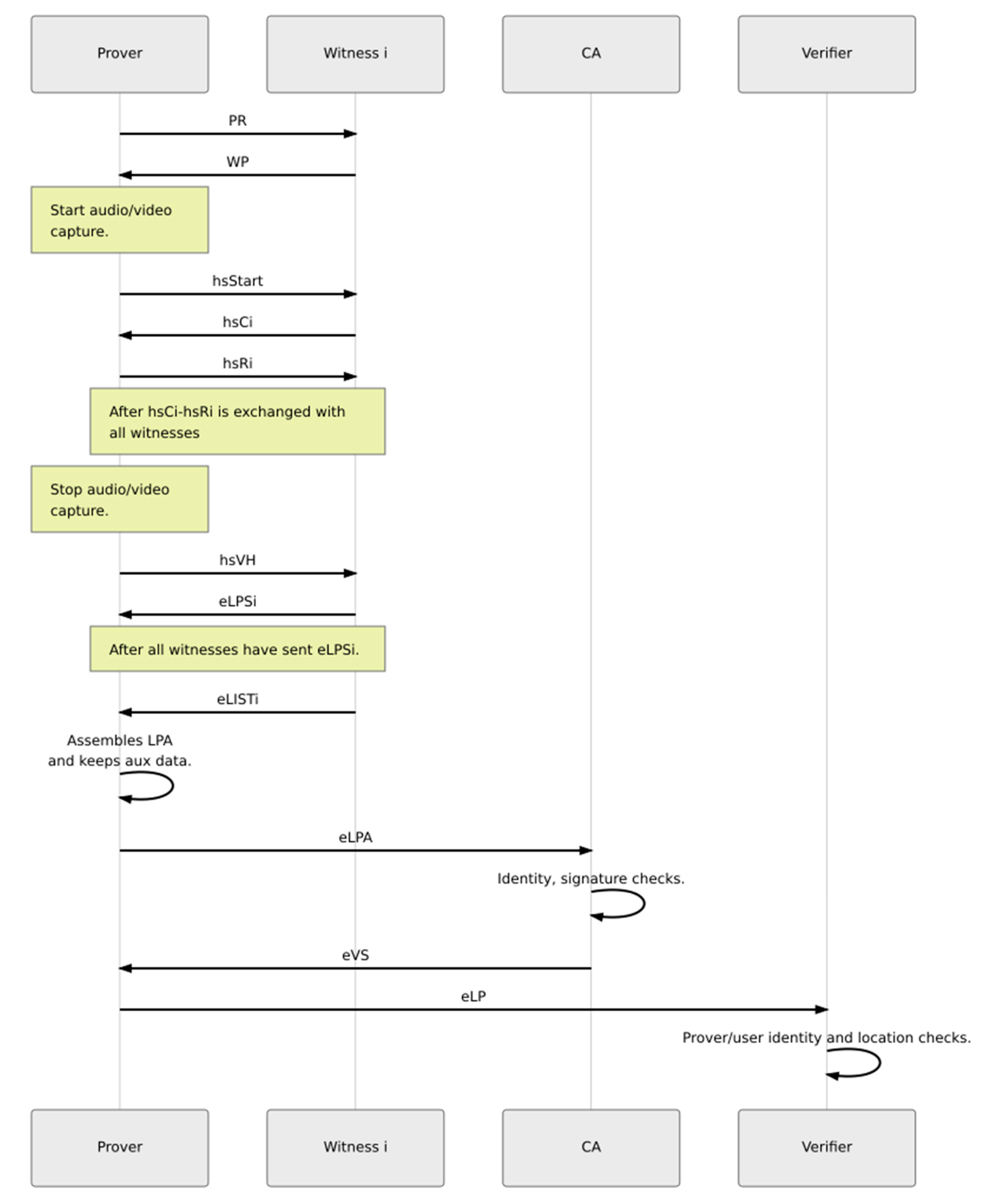
In this section we present the exact content of the messages being executed in QuietPlace. We suppose that prover P is near n witnesses Wi, 1 ≤ i ≤ n. V is the verifier and CA the certificate authority in use. The sequence diagram of communication among prover, witness, certification authority, and verifier is depicted in Figure 4, while a detailed description of the steps and communication is provided in the following section about proof of creation.
The notation we are going to use is shown in the table below (Table 1).
Encryption using public key is actually implemented by encrypting the message using a symmetric key, which is encrypted using the public key, as mentioned in Section 5.4.
6.1. Proof Creation
6.1.1. Meeting
When the user wants to obtain a new proof, they begin by broadcasting a Prover Request (PR) message.
where
PR = C(P, rp) |L0|K0|t1|CA
P: the prover’s identity
rp: nonce generated by the prover
L0: prover’s location with highest accuracy (10 characters plus code, represents a 14 m × 14 m square)
Κ0: the seed for the location chain
t1: prover’s current timestamp
CA: CA’s identity (i.e., hostname)
Each witness checks that their location expressed as a 10-character plus code matches the one reported by the prover, by checking the reported area ‘square’ and the neighboring ones. The 14 × 14 m area is sufficient for the range of ultrasound messages. Also, each witness checks that the prover’s timestamp t1 is valid. The witness will use the identity with which they are registered with the prover’s selected CA and reply with a Witness Presence (WP).
where
WP = C(Wi, rwi) |ni
Wi: identity of witness i
rwi: nonce generated by the witness i
ni: nonce
The prover begins capturing video and constructs Start (S) message
where
Start = C(P, rp)|Kn|t|h(f1)
Kn: the head of the location chain
t: current timestamp
h(f1): hash of the first frame of video
The prover broadcasts the following message:
hsStart = Start|hSkp(Start)
Each witness now checks that Kn is a valid location chain for the L0, K0 in PR and that t is a valid timestamp. If the above are valid, the witness saves the timestamp tSrec at which it received Start.
6.1.2. Proximity Test (Challenge-Response)
The witness constructs their challenge
where
Ci = C(Wi, rwi) |n1i|n2i
n1i: nonce that the prover device has to respond with
n2i: nonce that the user has to read out loud
Witness sends the message
hsCi = Ci|hSkwi(Ci)
P receives the above. The user reads out loud the nonce n2i.
The prover constructs the response
and sends the message
Ri = C(P, rp) |n1i|n2i
hsRi = Ri|hSkp(Ri)
Each witness now counts the round trip time – RTT between C and R and makes a decision. The RTT threshold to accept the prover’s claim is witness-specific. However, the verifier will be later able to count it themselves. The witness also saves the timestamp tRrec at which they received response hsRi. The decision can be represented with a bit. A 0 value means negative and 1 means positive answer by the witness.
6.1.3. LPS Gathering
After the challenge-response is completed with all the available witnesses, the prover stops video recording, calculates the hash of the video file, h(vid), and constructs the Video Hash (VH) message
and broadcasts the message
to the witnesses.
VH = C(P, rp)|h(vid)
hsVH =VH|hSkp(VH)
Each witness saves the timestamp tVHrec at which it received VH and constructs the Location Proof Segment (LPS)
and sends the following to P
where
LPSi = Wi|h(Start)|hsCi|hsRi|Skwi(Ci)|rwi|decision|hsVH|tSrec|tRrec|tVHrec
eLPSi = C(Wi, rWi)|EKCA(LPSi)
Wi: identity of witness i
rwi: nonce generated by the witness i
LPSi is encrypted and can be read only by the CA. Wi prove their identity by including rWi and Skwi(Ci) in the LPS.
6.1.4. Swarm Integrity
After witnesses finish sending their LPSs, it is time for them to create the lists with the witnesses that participated in the protocol session. Each witness Wi creates a list WPlist, containing the committed identities of witnesses that according to Wi sent a Witness Presence, including themselves. Also, Wi creates a list LPSlist, containing the committed identities of all witnesses that according to Wi sent an LPS, including itself.
It constructs
and sends
to the prover.
LISTi = WPlist|LPSlist = C(W1, rw1)|...|C(Wn, rwn)|C(W1, rw1)|...|C(Wn, rwn)
eLISTi = C(Wi, rWi)|EKCA(LISTi|SkWi(LISTi))
6.1.5. Proof Assembly
P has now collected all the needed information to create the Location Proof Assertion (LPA). He only needs to add the information that identifies him, such as the nonce for the commitment and the signatures for the messages they sent.
He assembles the Location Proof Assertion (LPA)
LPA=P|rp|Start|Skp(Start)|Skp(VH)|eLPS1|eLIST1|Skp(R1)|…| eLPSn|eLISTn|Skp(Rn)
The prover P saves the above message in his memory and can use it whenever he wants to verify the location included in it.
Alongside with LPA, P must keep the commitment C(P, rp) and the location-related information L0, K0 in order to use them later, as auxiliary information
aux = C(P, rp)|L0|K0
6.2. Proof Verification
The proof verification phase consists of two steps that can be separately executed in a different time.
6.2.1. Certificate Authority Checks
The prover encrypts the previous LPA message using CA’s public key, so that only the CA can decrypt it. P sends the following to the CA
eLPA = C(P, rp)|EKCA(LPA|Skp(LPA))
The CA is responsible to verify the prover’s commitment and signatures. Also, for every LPS the CA verifies the witness commitment, its signatures, that h(Start) refers to the Start message and also the signatures of the prover for its messages included in the LPS. If a signature is invalid, the LPS is discarded. For every valid LPS, the CA checks that the random numbers are the same in the challenge and response. It also takes the witness answer into consideration. The CA also checks the LIST messages and excludes witnesses with suspected behavior. After having collected all the valid LPSs, the CA applies its trust scheme.
In case a witness is trusted to the CA, its opinion has priority over the rest in the trust scheme in use. In case a witness is trusted to the verifier, the CA can include its identity along with its decision.
The CA also constructs the Session Fingerprint (SF)
which is produced by hashing all the challenge and response messages that were included in the LPSs, in the order they were sent to the prover. It is meant to assist the Verifier check that the audio recording corresponds to that session.
SF = h(Start|C1|R1|…|Cn|Rn)
The CA constructs the Verifier Segment (VS)
where
VS = (CA|Start|P|h(vid)|SF|score1|ans1|…|scorem|ansm|tSmean|tRmean|tVHmean
m: the total valid LPSs, m ≤ n
score: the trust score for each LPS according to the trust scheme being used
ans: the corresponding answer (0 = decline, 1 = accept)
tSmean, tRmean, tVHmean: the mean timestamp values reported by witnesses
The CA encrypts and signs the VS, and sends the following to the Prover:
eVS = CA|EkCA(VS)|SkCA(VS)
6.2.2. Verification
All the information in the possession of the prover do not refer to a specific verifier (verifier-agnostic). The above information, verified by the CA, can be used with one or more verifiers.
The prover creates the Location Proof (LP)
where Ki, Li are the part of the location chain and the location granularity level respectively.
LP = P|Start|eVS|Ki|Li|vid
Now the proof becomes verifier-specific by encrypting it using the verifier’s public key. The below message is sent to V.
eLP = EKV(LP|Skp(LP))
The verifier checks the signatures, hashes, and the location chain.
As for the video, V has to check that the legitimate owner appears and that he is reading the numbers included in the ultrasound responses. He can perform any check that he wants as he can listen the ultrasound session. A quick check is to verify the Session Fingerprint provided by the CA.
The protocol now completes. The verifier takes all information into consideration to make a decision of whether they will accept or decline the prover’s proof.
6.3. QuietPlace Characteristics
7. Security and Privacy Analysis
7.1. Specifications of PoL protocols
Proof of location protocols must satisfy certain specifications that guarantee their secure operation and make sure that they respect the involved users’ privacy. Based on [4] and after an extensive study of the protocols in the literature, we present the specifications that an ideal protocol should satisfy regarding security and privacy.
Security specifications that have been considered include:
- Data integrity/unforgeability: It must be impossible for a user to tamper with the messages they receive from other users without that being evident to checking entities.
- Inability to hide or add LPSs: The prover must be unable to add or remove assertions received by witnesses during a protocol session to the proof the prover sends to the verifier. This ensures that every witness’s opinion is respected and that the prover does not secretly cooperate with witnesses that do not openly participate in the session.
- Non-transferability: The proof created for/by the prover is bound to their identity and cannot be claimed by (or transferred to) another user of the system.
- Resistance to distance fraud: The protocol must make sure that a proximity test is executed between prover and witness. This ensures that the prover cannot lie about being closer to the witness than they truly are.
- Resistance to mafia fraud (man-in-the-middle): Every protocol session between a prover and a witness must be unique. The messages must be related to the sender’s identity. The protocol must also use a method for identifying the existence of a man-in-the-middle.
- Resistance to distance hijacking: The LPSs produced by the witnesses refer to a specific proof request made by the prover, for whom a proximity test is executed. These LPSs are useless for any other malicious prover.
- Resistance to P-P collusion: It must be impossible for a prover P’ to collect LPSs that certify the position of another prover P. This specification is met by combining non-transferability, resistance to distance fraud, mafia fraud, and distance hijacking.
- Resistance to P-W collusion: A prover should never learn the identity of a witness that sent an LPS and whether the witness approved or rejected their claim. If the prover’s claim is rejected, it is desirable that the witness sends a rejecting LPS, instead of not sending an LPS at all. In this way, the prover is unaware of the witness’s decision.
- Resistance to W-W collusion: Witnesses must be unaware of other witnesses’ identities or whether other witnesses approved or rejected the prover’s claim.
- LPS uniqueness: Only one LPS per witness must be included in every created PoL.
- No single point of failure: Dependency on entities that may make the entire system unusable in case of failure (i.e., if they get attacked) must be avoided.
Privacy specifications that have been considered include:
- Anonymity during proof creation: The identities of the prover and the witnesses that are involved in a PoL creation session must be hidden from everyone. This translates to protection from malicious eavesdroppers and P-W or W-W cooperation.
- Anonymity during proof verification: The verifier must be able to learn the identity of the prover. They must be unable to identify the witnesses that participated in the PoL creation, unless they belong to the witness and thus are considered trusted. The CA may also learn the users’ identity in order to perform checks and evaluate their behavior. No one else should be able to identify the involved users.
- Prover location privacy: The location of the prover must be known only to the witnesses that are close to the prover and the verifier.
- Witness location privacy: The location of the witnesses must not be revealed in the assertions they send to the prover. It is preferable that they include their distance from the prover, as it is enough to know that they are close to each other.
- Proof ownership: The PoL that is created belongs to the prover, who keeps it saved in their device until they decides to send it to the verifier. The prover is not required to reveal information that can expose their identity before or after the creation of the proof.
7.2. Specifications of QuietPlace
In the two tables below (Table 3 and Table 4), we investigate whether QuietPlace covers the above specifications.
To sum up, QuietPlace covers all the security and privacy specifications.
7.3. Resistance to Man-in-the-Middle Attacks
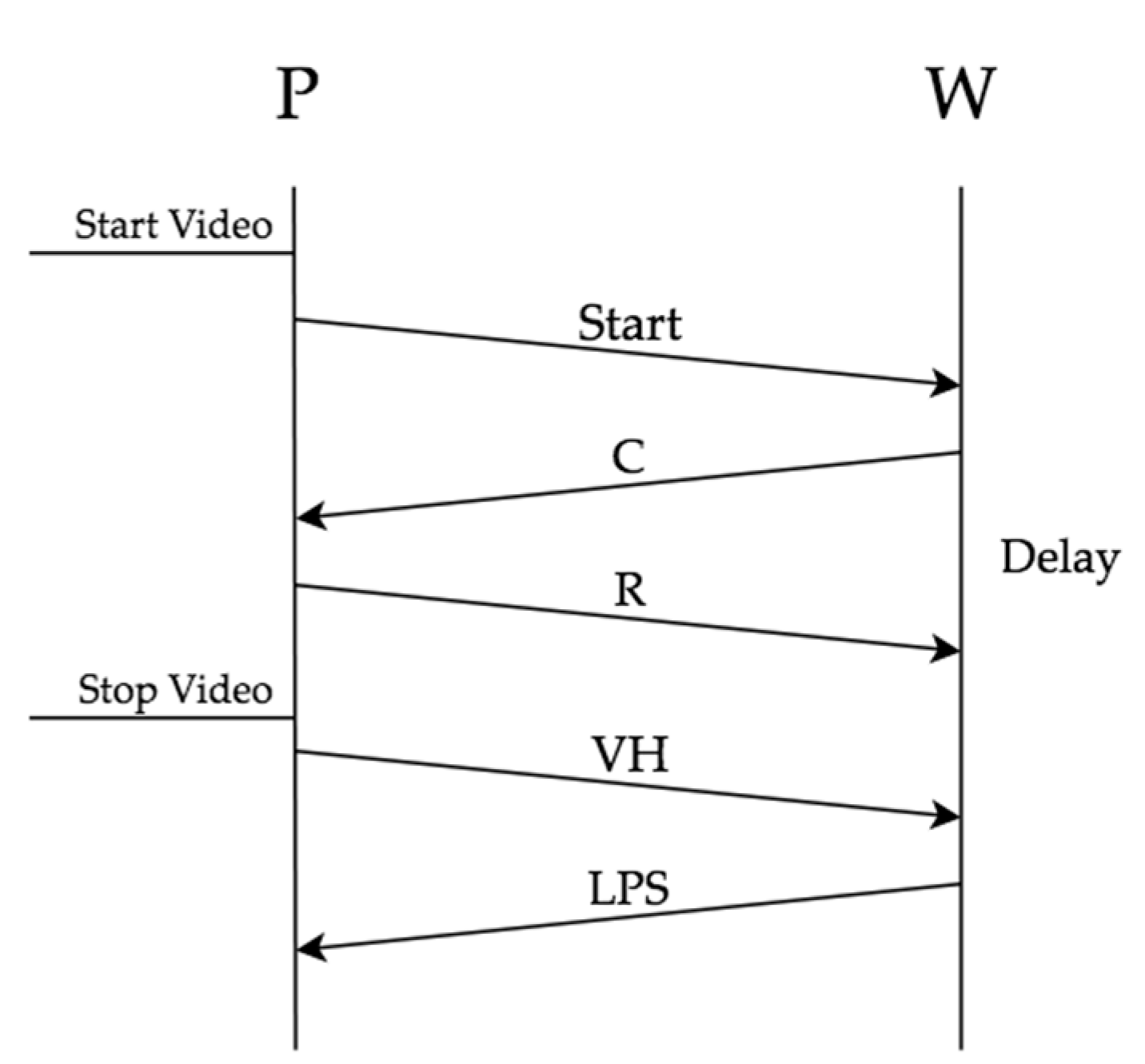
In this section, we present how the combination of video capturing and ultrasound communication ensures that our protocol resists to common man-in-the-middle attacks while producing strong identity proofs. In the diagrams below, we include a simplified part of the exchanged messages that is needed for the analysis. We consider having a prover P and a witness W. Under normal circumstances, the witness takes the delay between C and R into consideration, in order to estimate whether the prover is near, as shown in Figure 5.
We now suppose that a man-in-the-middle M intercepts and retransmits the messages exchanged between P and W. The physical owner captures the video using the P device. M is close to W and will try to make them believe that they are P. We consider two cases. In the first, M simply relays the messages of P to W and the opposite. In the second case, M possesses the key pair of P.
Regardless of the case, the need to convert ultrasound messages to another type of physical layer adds significant delay in the overall message transmission. Such a delay is very critical for the validation of the proximity between P and W, as we present in the following subsections.
7.3.1. Simple Relay
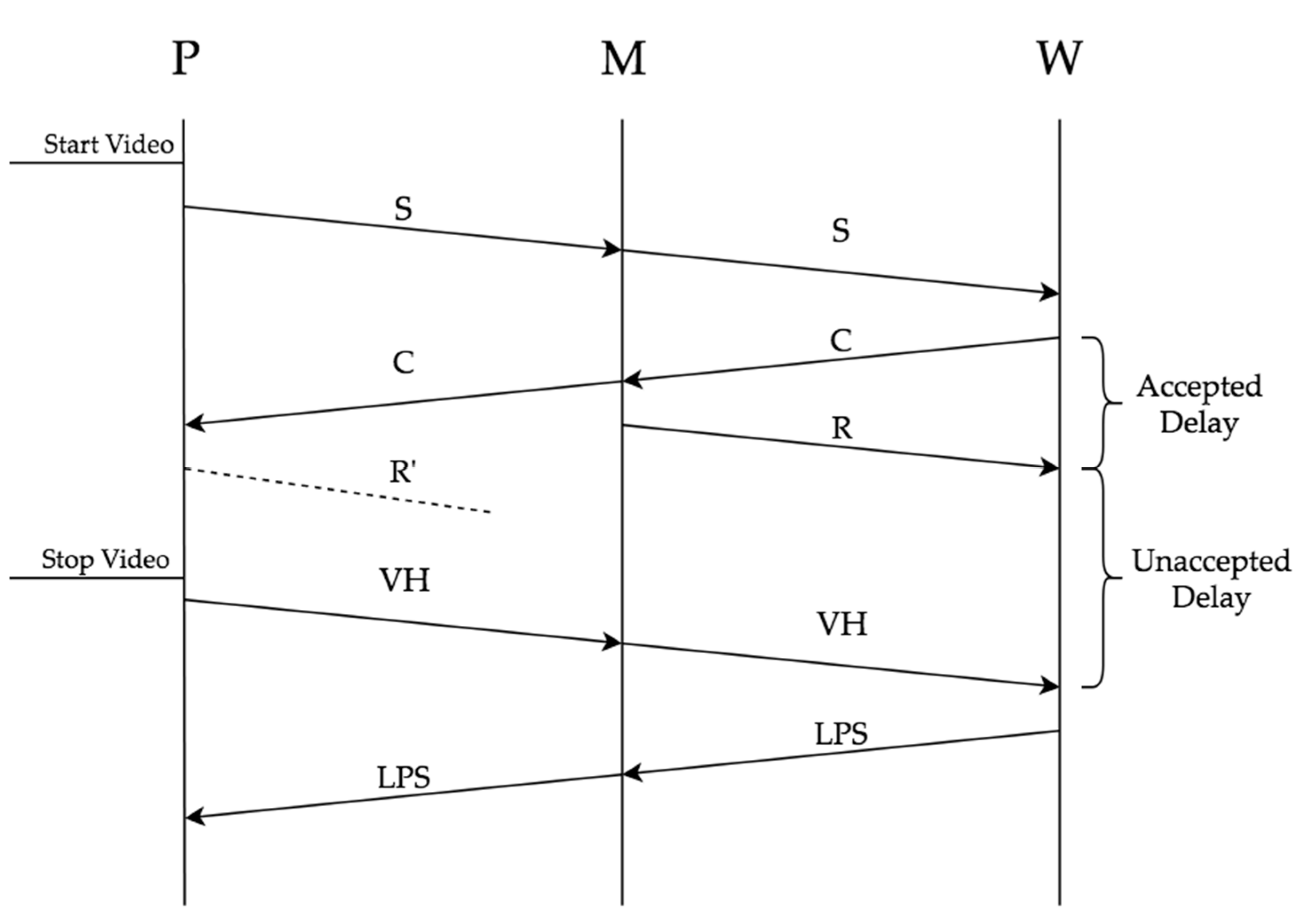
M simply retransmits messages between P and W, as explained in [8].
The witness can simply observe the delay between the challenge and response, as shown in Figure 6. As a result, the proximity test between P and W fails.
7.3.2. Duplicates
In this case, M and P share the same keys and identity, appearing as the same device. M can answer immediately to W, because it can sign the messages as P. P device produces fake ultrasound messages so that it appears that it answers immediately. Fake messages are shown with a dashed line in Figure 7.
In certain situations, when the video hash computation can be considered a quick and time-predictable operation which can be performed within a strict deadline, the delay between the response (R) and video hash (VH) could be detected by W. However, this is not the main security-critical deadline set by QuietPlace. Even if the R to VH delay is ignored, the difference between (Start-R’) in the video captured by P and (Start-R) as perceived by W uncovers the existence of M (thus reverting back to the Simple Relay scenario). P can try to pause the video capture in order to make the time differences appear smaller or identical. In this case though, the video will be significantly smaller than the total protocol execution time. Also, more importantly, the pause will be noticeable to a viewer of the video. It should be noted that, not only the time differences can be detected, but also the timestamps for Start, R and R’.
To make the above time differences available to the verifier, we require each witness to save a timestamp for Start, R and VH, as we described in the previous section. Our proposal for strong identities binds the user with the device, making it impossible for a malicious device to obtain a valid proof, even it shares the same credentials with the prover device.
8. Implementation
The protocol was implemented as an application for Android-based smartphones. For the ultrasound communication between the prover and witness, Quiet for Android [31] was used. Quiet for Android is based on the digital signal processor liquid-dsp [32]. Quiet can be used either in frame layer mode, where messages are broadcasted as frames, or in UDP/TCP mode, where messages are send over the IP protocol. In our implementation the simple frame layer mode was used.
Quiet supports many audio profiles, either audible or inaudible (ultrasound). It comes with some presets but also gives the opportunity for fine configuration and creation of custom profiles. Quiet Profile Lab [33] is an online tool that helps with testing user-defined configurations and extracting the configuration file for Quiet, easily creating a new profile.
Before starting the implementation of QuietPlace, we set up two experiments in order to compare the performance of each preset profile in Quiet, except for “cable-64k”, which is meant for transmission over a cable. We used QuietShare [34], a message sharing application for Android that uses Quiet in frame layer mode. The two devices we used were a Xiaomi Redmi Note 5 as a transmitter and a Samsung Galaxy S6 as a receiver.
In the first experiment, we measured the maximum distance for which message reception is possible. The two devices were put in a way that the speaker of the transmitter is always facing the microphone of the receiver. As the purpose was to compare the different profiles, we kept the volume setting of the transmitter unchanged throughout the experiment. For each profile, we gradually moved the transmitter away from the receiver, each time sending the message “testmessage” and checking whether the receiver successfully received it or not, until message was no more received. The results are shown in the below table (Table 5).
From the above table, we conclude that ultrasound-based profiles offer a far better performance in terms of receiving distance than audible profiles.
In the second experiment, we measured the directionality of each profile. The receiver remained stationary during the experiment. We made sure that its speaker was always targeting the receiver and that the distance between speaker and microphone was 30 cm. For each profile, we rotated the transmitter around the receiver, 10 degrees at a time, sending the message “testmessage” each time and checking whether it was received or not. We consider as 0° the placement of the devices where the speaker is facing the microphone and we count clockwise. We note the points where the message was received with ‘1’ and the rest with ‘0’. The reception points are shown in Figure 8.
In QuietPlace, the ‘ultrasound-experimental’ profile is used, which showed almost the biggest range and the smallest directionality in our tests. The ultrasound communication performed well in a room with normal noise levels. Also, the ultrasound profiles were found to be less vulnerable to noise. When the distance of the devices was below the maximum receiving distance, we rarely observed message loss. The sum of the time needed for the QuietPlace messages to be exchanged between a prover and a witness was about 32 s, which is acceptable when i.e., two people meet or when an employee sits at their office. However, it could be a problem for moving users. Also, the time is increased when more witnesses are present. During our tests with Quiet Profile Lab [33], the throughput of ‘ultrasound’ profile was measured at about 500–550 bps, explaining the above duration. Optimizing the throughput and speed of ultrasound transmission is out of the scope of this paper and is left for future research.
The messages were represented as Java objects and were sent using the JSON format. For example, the WP message is represented as the below class

For geocoding, we used the official Plus Codes library for Java [35]. Random numbers, encrypted messages, hashes and signatures were represented as Base64 strings. For hashing, we used the SHA-256 algorithm, for asymmetric cryptography the RSA system with 1024-bit key length and for symmetric cryptography the AES algorithm with 128-bit key length. Digital signatures were produced and verified using SHA-256 with RSA.
The application consists of the two screens that are shown in Figure 9. The user starts by tapping on ‘Start Location Updates’. The device location is shown as coordinates and plus code. When the accuracy is good enough, the user can stop the location updates and proceed to the second screen by tapping on request/issue proof. Then, the user can run the protocol as either a prover or a witness. The witness must press the button before the prover and almost immediately, so that the prover sends the PR message while the witness starts listening. On the prover’s screen, the random number that has to be read loudly is shown on the screen after the reception of the challenge message from the witness. At the end of the proof creation phase, the prover has constructed the LPA message. The proof verification phase which consists of CA and verifier procedures is emulated on the prover’s device by tapping on the corresponding buttons. We decided to emulate this phase of our protocol because we cared about the cryptographic validations and not the communication between prover, CA and Verifier, which can be easily accomplished with REST web services. The whole procedure can be observed by debugging the application using Android Studio and viewing the logs. After the communication between prover and witness is complete, by pressing the ‘CA Emulation’ button on the prover device, the check of the eLPA message and the production of eVS message is performed locally on the device. Next, pressing the ‘Create LP’ button, the prover creates the eLP message using the required information as described in Section 6. Finally, by pressing ‘Verifier Emulation’, the prover locally performs the identity and location check of eLP. The selection of Android devices is justified by our focus on following a user-oriented approach. According to [36], an increasing number of individuals own a mobile device (more than 5 billion phone numbers in 2019), with Android being the most widely used operating system for smart phones, tablets, and mobile devices [37]. It is important to notice that our application could be migrated to run on other operating systems such as iOS, using dedicated development frameworks such as Flutter [35]. However, since our focus was concentrated on implementing generic mobile applications, we examined the use of the app in a simulation environment and use it as testbed for examining and verifying that the functionality meets the design of our proof of location process and successfully handles the different test use cases defined.
9. Discussion, Conclusions, and Future work
In this paper, we described the participating entities, the malicious users and common attacks in proof of location protocols. We presented the characteristics of PoL protocols and thoroughly examined the problem of strong identities, proposing a novel solution. We identified and solved the technical challenges we faced. We later introduced QuietPlace, a proof of location protocol that is based on ultrasound communication and provides unforgeable, private proofs that support strong identities. Ultrasound makes it difficult to carry messages over long distance without having to convert them to another form. This makes man-in-the-middle attacks more difficult to succeed, as the additional delay can be easily observed. The cryptographic techniques that we proposed separate knowledge between CA and verifier. The CA validates the user identities while the verifier validates the location of the prover of concern. In this way, the credibility of the users is maintained without sacrificing privacy. We also analyzed the security and privacy performance of QuietPlace, comparing it with other protocols in literature. By proving the physical user’s location using audio/video capture on the prover device, we managed to solve the problem of multiple devices that carry the same user’s credentials. To the best of our knowledge, this is the first attempt of a proof of location protocol to provide a complete solution to this issue.
It is left for future research work to enhance the current implementation with a medium access control protocol, as messages are broadcasted via ultrasound and collisions may occur. Also, in order to start the procedure, the witness listens until it receives a PR message from a prover. This is something which can be further extended in order to increase privacy considerations for the user of the mobile phone. Apart from solving the above issues, the CA and verifier can be implemented on a server instead of being emulated on the prover’s device. Also, we would like to experiment with ultrasound communication, so that bigger range, smaller directionality, and more throughput is achieved. Manually configuring liquid-dsp could be the first step. Finally, it is important that more compact message encoding is being used, so that it takes less time for the protocol execution to be completed. In general, the way the CA can evaluate the behavior of the participants is of great scientific interest.
To sum up, the scope of this study has been (as a first step) to develop a PoL protocol that can tackle most (if not all) security and privacy vulnerabilities that can appear in other PoL mechanisms. As it has been presented in Section 7.2, QuietPlace seems to cover these security and privacy threats of interest in a sufficient manner. The first steps towards implementation of the protocol and testing of the requirements and performance on the physical layer have already been taken, as presented in Section 8. Aspects like performance, execution time, code/encoding optimization, and time and space complexity of the algorithm are out of the scope of this study per se and are the primary subject for future research and work for the further enhancement of the protocol.
Author Contributions
Conceptualization, D.K., O.V., A.L., and T.V.; Formal analysis, D.K. and A.L.; Funding acquisition, A.L.; Investigation, G.P.; Methodology, D.K., O.V., G.P., and A.L.; Project administration, A.L. and T.V.; Software, D.K. and O.V.; Supervision, A.L. and T.V.; Validation, D.K. and G.P.; Writing—original draft, D.K., O.V., and A.L.; Writing—review and editing, O.V., G.P., A.L., and T.V. The authors collaborated on all sections of the paper and all authors participated in all writing and revising. All authors have read and agreed to the published version of the manuscript.
Funding
The research leading to these results has received funding from the European Commission under the H2020 Programme’s project M-Sec. The M-Sec project is jointly funded by the European Union’s Horizon 2020 research and innovation programme (contract no. 814917) and by the Commissioned Research of National Institute of Information and Communications Technology (NICT), JAPAN (contract no. 19501). The APC was funded by the Institute of Communication and Computer Systems (ICCS) of the School of Electrical and Computer Engineering (ECE) of the National Technical University of Athens (NTUA).
Conflicts of Interest
The authors declare no conflict of interest.
References
- Luo, W.; Hengartner, U. Veriplace: A privacy-aware location proof architecture. In Proceedings of the 18th SIGSPATIAL International Conference on Advances in Geographic Information Systems; ACM: New York, NY, USA, 2010; pp. 23–32. [Google Scholar]
- Lyu, C.; Pande, A.; Wang, X.; Zhu, J.; Gu, D.; Mohapatra, P. CLIP: Continuous location integrity and provenance for mobile phones. In Proceedings of the 2015 IEEE 12th International Conference on Mobile Ad Hoc and Sensor Systems, Dallas, TX, USA, 19–22 October 2015; pp. 172–180. [Google Scholar]
- Foamspace Corp. FOAM Whitepaper. 5 January 2018. Available online: https://foam.space/publicAssets/FOAM_Whitepaper.pdf (accessed on 4 March 2019).
- Gambs, S.; Killijian, M.; Roy, M.; Traor’e, M. PROPS: A privacy-preserving location proof system. In Proceedings of the 2014 IEEE 33rd International Symposium on Reliable Distributed Systems, Nara, Japan, 6–9 October 2014; pp. 1–10. [Google Scholar]
- Zhu, Z.; Cao, G. Applaus: A privacy-preserving location proof updating system for location-based services. In 2011 Proceedings IEEE INFOCOM; IEEE: New York, NY, USA, 2011; pp. 1889–1897. [Google Scholar]
- Luo, W.; Hengartner, U. Proving your location without giving up your privacy. In Proceedings of the Eleventh Workshop on Mobile Computing Systems & Applications, Annapolis, MA, USA, 22–23 February 2010; ACM: New York, NY, USA, 2010; pp. 7–12. [Google Scholar]
- Holiday, M.; Mittal, N.; Venkatesan, S. Secure location verification with randomly-selected base stations. In Proceedings of the 2011 31st International Conference on Distributed Computing Systems Workshops, Minneapolis, MI, USA, 20–24 June 2011; pp. 119–122. [Google Scholar]
- Vora, A.; Nesterenko, M. Secure location verification using radio broadcast. IEEE Trans. Dependable Secur. Comput. 2006, 3, 377–385. [Google Scholar] [CrossRef]
- Rasmussen, K.; Srivastava, M. Secure location verification with hidden and mobile base stations. IEEE Trans. Mob. Comput. 2008, 7, 470–483. [Google Scholar]
- Rasori, M.; Perazzo, P.; Dini, G. A Low-Cost UAV-Based Secure Location Verification Method. In Proceedings of the 12th International Conference on Availability, Reliability and Security, Reggio Calabria, Italy, 29–31 August 2017; pp. 1–6. [Google Scholar]
- Davis, B.; Chen, H.; Franklin, M. Privacy-preserving alibi systems. In Proceedings of the 7th ACM Symposium on Information, Computer and Communications Security, Seoul, Korea, 2–4 May 2012; ACM: New York, NY, USA, 2012; pp. 34–35. [Google Scholar]
- Mansoor, K.; Ghani, A.; Chaudhry, S.A.; Shamshirband, S.; Ghayyur, S.A.K.; Mosavi, A. 2019. Securing IoT-Based RFID Systems: A Robust Authentication Protocol Using Symmetric Cryptography. Sensors 2019, 19, 4752. [Google Scholar] [CrossRef] [PubMed] [Green Version]
- Saroiu, S.; Wolman, A. Enabling new mobile applications with location proofs. In Proceedings of the 10th workshop on Mobile Computing Systems and Applications; ACM: New York, NY, USA, 2009; p. 3. [Google Scholar]
- Zhang, Y.; Tan, C.C.; Xu, F.; Han, H.; Li, Q. Vproof: Lightweight privacy-preserving vehicle location proofs. IEEE Trans. Veh. Technol. 2014, 64, 378–385. [Google Scholar] [CrossRef]
- Sastry, N.; Shankar, U.; Wagner, D. Secure verification of location claims. In Proceedings of the 2nd ACM Workshop on Wireless Security; ACM: New York, NY, USA, 2003; pp. 1–10. [Google Scholar]
- Wang, X.; Pande, A.; Zhu, J.; Mohapatra, P. STAMP: Enabling privacy-preserving location proofs for mobile users. IEEE/ACM Trans. Netw. 2016, 24, 3276–3289. [Google Scholar] [CrossRef]
- Miettinen, M.; Asokan, N.; Koushanfar, F.; Nguyen, T.D.; Rios, J.; Sadeghi, A.; Sobhani, M.; Yellapantula, S. I know where you are: Proofs of presence resilient to malicious provers. In Proceedings of the 10th ACM Symposium on Information, Computer and Communications Security, Singapore, 14–17 April 2015; ACM: New York, NY, USA, 2015; pp. 567–577. [Google Scholar]
- Brambilla, G.; Amoretti, M.; Zanichelli, F. Using blockchain for peer-to-peer proof-of-location. arXiv 2016, arXiv:1607.00174. [Google Scholar]
- Plus Codes. Available online: https://plus.codes/ (accessed on 15 October 2019).
- Hasan, R.; Burns, R. Where have you been? Secure location provenance for mobile devices. arXiv 2011, arXiv:1107.1821. [Google Scholar]
- Hasan, R.; Khan, R.; Zawoad, S.; Haque, M.M. WORAL: A witness oriented secure location provenance framework for mobile devices. IEEE Trans. Energy Top. Comput. 2015, 4, 128–141. [Google Scholar] [CrossRef]
- Güera, D.; Delp, E.J. Deepfake Video Detection Using Recurrent Neural Networks. In Proceedings of the 2018 15th IEEE International Conference on Advanced Video and Signal Based Surveillance (AVSS), Auckland, New Zealand, 27–30 November 2018; pp. 1–6. [Google Scholar]
- Evaluation of Location Encoding Systems. Available online: https://github.com/google/open-location-code/wiki/Evaluation-of-Location-Encoding-Systems (accessed on 16 October 2019).
- Lenzini, G.; Mauw, S.; Pang, J. Selective location blinding using hash chains. In International Workshop on Security Protocols; Springer: Berlin, Germany, 2011; pp. 132–141. [Google Scholar]
- Townsend Security. How much data can you encrypt with RSA keys? Available online: https://info.townsendsecurity.com/bid/29195/how-much-data-can-you-encrypt-with-rsa-keys (accessed on 29 August 2019).
- Geocoding—GIS (Geographic Information Systems)—Library Guides at UC Berkeley. Available online: https://guides.lib.berkeley.edu/gis/geocoding (accessed on 19 October 2019).
- Goldberg, D.W.; Ballard, M.; Boyd, J.H.; Mullan, N.; Garfield, C.; Rosman, D.; Ferrante, A.M.; Semmens, J.B. An evaluation framework for comparing geocoding systems. Int. J. Health Geogr. 2013, 12, 50. [Google Scholar] [CrossRef] [PubMed] [Green Version]
- Location Encoding Systems—Could Geographic Coordinates be Replaced and at What Cost? Available online: https://gogeomatics.ca/location-encoding-systems-could-geographic-coordinates-be-replaced-and-at-what-cost/ (accessed on 19 October 2019).
- Halevi, S.; Micali, S. Practical and provably-secure commitment schemes from collision-free hashing. In Annual International Cryptology Conference; Springer: Berlin, Germany, 1996; pp. 201–215. [Google Scholar]
- Pedersen, T.P. Non-interactive and information-theoretic secure verifiable secret sharing. In Annual International Cryptology Conference; Springer: Berlin, Germany, 1991; pp. 129–140. [Google Scholar]
- GitHub—quiet/org.quietmodem.Quiet: Quiet for Android—TCP over sound. Available online: https://github.com/quiet/org.quietmodem.Quiet (accessed on 15 October 2019).
- liquidsdr.org. Available online: https://liquidsdr.org/ (accessed on 15 October 2019).
- Quiet Profile Lab. Available online: https://quiet.github.io/quiet-profile-lab/ (accessed on 23 November 2019).
- GitHub—Alexbirkett/QuietShare: Android app to Send Messages between Phones Using Audio. Available online: https://github.com/alexbirkett/QuietShare (accessed on 23 November 2019).
- Android v iOS market share 2019. Available online: https://deviceatlas.com/blog/android-v-ios-market-share (accessed on 15 October 2019).
- How many smartphones are in the world? Available online: https://www.bankmycell.com/blog/how-many-phones-are-in-the-world (accessed on 15 October 2019).
- Flutter. Available online: https://flutter.dev/ (accessed on 15 October 2019).
Figure 1.
Entities participating in the creation of a proof of location with strong identities.

Figure 2.
The considered system model, including all possible participating entities and a description of the exchanged messages.
Figure 2.
The considered system model, including all possible participating entities and a description of the exchanged messages.

Figure 3.
A simple hash chain, created by successively applying a hash function.

Figure 4.
A sequence diagram of QuietPlace.

Figure 5.
Part of the messages exchanged between a prover P and a witness W.

Figure 6.
Man-in-the-middle M acts as a relay, simply retransmitting messages between prover P and witness W.
Figure 6.
Man-in-the-middle M acts as a relay, simply retransmitting messages between prover P and witness W.

Figure 7.
Man-in-the-middle (M) possesses the cryptographic keys of prover (P) and therefore is able to provide signed response (R) messages to the witness (W), without the need to retransmit them.
Figure 7.
Man-in-the-middle (M) possesses the cryptographic keys of prover (P) and therefore is able to provide signed response (R) messages to the witness (W), without the need to retransmit them.

Figure 8.
Reception diagrams for Quiet preset profiles.


Figure 9.
Screenshots of our prototype application: (a) The home-screen, used to retrieve the location of the device; (b) The protocol control screen.
Figure 9.
Screenshots of our prototype application: (a) The home-screen, used to retrieve the location of the device; (b) The protocol control screen.


Table 1.
The notation used in our protocol description.
| Notation | Meaning |
|---|---|
| m1|m2 | Concatenation of messages m1 and m2. |
| C(m, r) | Commitment of message m with nonce r. |
| h(m) | Hash of m using hash function h(). |
| Ek(m) | Encryption of message m using key k. |
| Sk(m) | Signature of message m using key k. |
| Κu | Public key of user u. |
| ku | Private key of user u. |
| hSk(m) | = h(Skey(m)): Hash of signature of message m using key k. |
Table 2.
Characteristics of QuietPlace.
| Characteristic | Solution | Description |
|---|---|---|
| Proof creation architecture | Hybrid | Witnesses can be other users’ devices or nodes trusted to the CA or/and the verifier. |
| Proof verification architecture | Indirect | The CA is involved in the verification process in order to verify the identities and signatures of the participants. |
| Use of a trusted third party/certificate authority | Yes | We use a certificate authority, which is responsible for keeping the public keys of the users, verifying their identities and signatures and detecting malicious nodes. It can optionally run a trust scheme to assess the users according to their behavior. |
| Physical layer | Ultrasound | Prover and witnesses communicate via ultrasound during the proof creation phase. The physical layer used in the verification phase is indifferent. |
| Geocoding | Plus codes | We represent location using plus codes of different size, according to the desired accuracy. |
| Geolocation | No | The protocol does not calculate the users’ location but verifies it. The location is obtained by the device OS. |
| Proximity test | Yes, timeout-based | The round-trip time between witness’s challenge and prover’s response is measured. Exceeding a specified threshold will cause the prover’s claim to be rejected. |
| Incentive to participate | Yes | The CAs can provide their services to verifiers with a cost. This motivates them to execute identity-checking procedures and expand their networks of trusted witnesses. |
| Location granularity levels | Yes | Using hash chains, the prover can reveal its location to the verifier with the accuracy of its choice. |
| Verifier-agnostic proofs | Yes | After CA performs its checks, the prover possesses verifier-independent information. The proof becomes verifier-specific with the creation of the final LP message. |
| Proof of location chains | No | The proposed protocol does not support proof of location chains. Every proof produced can be used by itself and is unrelated to others. |
Table 3.
Security specifications of QuietPlace.
| Security Specification | Covered | Description |
|---|---|---|
| Data integrity/ unforgeability | Yes | Sensitive information is protected with hashes, commitments, and encryption. It is impossible to modify messages without this being evident. |
| Inability to hide or add LPSs | Yes | The CA can verify how many witnesses were present during the proof creation session and how many sent an LPS to the prover. Thus, if the prover tries to add or remove an LPS from his LPA message, CA will detect it. |
| Non-transferability | Yes | The prover always signs his messages. The CA performs checks to verify the prover’s identity and signature. The checked information is included in VS, which is needed to construct the LP. Thus, no other user will be able to use the VS except from the user whose identity is included in it, which is only the legitimate prover. |
| Resistance to distance fraud | Yes | The protocol validates the proximity between prover and witness using challenge and response ultrasound messages. Not only do the witnesses count the RTT, but also the verifier can check that the RTT reported by each witness was correct, by listening to the messages in the video. The usage of ultrasound makes resistance to distance fraud stronger, as in order to transmit the messages in longer distances, conversion to another type of signal is required (i.e., electromagnetic). This increases delay, making the malicious nodes easy to be detected. |
| Resistance to mafia fraud (man-in-the-middle) | Yes | The usage of random nonces in the witness challenge messages ensures the uniqueness of the session. It is impossible for a man in the middle M to replay the session between P and W so that P obtains a valid proof, even if he is in the possession of P’s keys. |
| Resistance to distance hijacking | Yes | The LPSs produced by the witnesses and sent to the prover contain session-specific data. Also, messages are signed and the CA performs identity and signature checks. Thus, a user cannot use an LPS that belongs to the legitimate prover who earned it. |
| Resistance to P-P collision | Yes | The satisfaction of the above specifications ensures that our protocol prevents a prover P’ from cooperating with another prover P, so that P’ obtains a proof for P. Even if P has shared his keys with P’, the demand for strong identities reveals the cooperation. |
| Resistance to P-W collision | Yes | The prover does not know the identity of the witnesses he communicates with. Also, he does not learn their decision, which is sent encrypted. The requirement for the witnesses to send a list with other witnesses they discover is an additional mechanism for P-W collusion detection. |
| Resistance to W-W collision | Yes | Witnesses do not know each other’s identity or the decision they made. |
| LPS uniqueness | Yes | The CA checks that the LPA it receives by the prover contains one and only one LPS from each witness. |
| No single point of failure | Yes | The CA can become a single point of failure if it malfunctions. However, the users can be also registered to other functional CAs. Also, the prover can keep the LPA until the CA recovers. |
Table 4.
Privacy specifications of QuietPlace.
| Privacy Specification | Covered | Description |
|---|---|---|
| Anonymity during proof creation | Yes | In the messages exchanged during proof creation, prover and witness identities appear in commitments and their signatures are hashed. An eavesdropper cannot identify the users involved. |
| Anonymity during proof verification | Yes | The verifier learns the prover’s identity. The verifier does not learn the witnesses’ identity, but only their decision, except if they belong to him (verifier-trusted witnesses). The CA learns both prover and witness identities, so that it can assess them using a trust scheme. However, no location-related information is disclosed to the CA. |
| Prover location privacy | Yes | Only witnesses learn the prover’s exact location, so that they can validate it. With the use of a location chain, the prover discloses his location to the verifier at his desired accuracy. |
| Witness location privacy | Yes | Witnesses never disclose their location. They only validate that the prover is near them. |
| Proof ownership | Yes | After the completion of the proof creation phase, the prover constructs his LPA message and saves it in his memory. When called to verify his location, the prover starts the verification phase by communicating with the CA. He is not obliged to reveal any information before the verification phase and is the only and legitimate owner of the LPA. |
Table 5.
Maximum receiving distance for each Quiet preset profile.
| Quiet Profile | Maximum Receiving Distance (cm) |
|---|---|
| Audible | 55 |
| Audible-7k-channel-0 | 59 |
| Audible-7k-channel-1 | 42 |
| Hello-world | 56 |
| Ultrasonic | 147 |
| Ultrasonic-3600 | 105 |
| Ultrasonic-whisper | 235 |
| Ultrasonic-experimental | 232 |
© 2020 by the authors. Licensee MDPI, Basel, Switzerland. This article is an open access article distributed under the terms and conditions of the Creative Commons Attribution (CC BY) license (http://creativecommons.org/licenses/by/4.0/).
Share and Cite
MDPI and ACS Style
Kounas, D.; Voutyras, O.; Palaiokrassas, G.; Litke, A.; Varvarigou, T. QuietPlace: An Ultrasound-Based Proof of Location Protocol with Strong Identities. Appl. Syst. Innov. 2020, 3, 19. https://doi.org/10.3390/asi3020019
AMA Style
Kounas D, Voutyras O, Palaiokrassas G, Litke A, Varvarigou T. QuietPlace: An Ultrasound-Based Proof of Location Protocol with Strong Identities. Applied System Innovation. 2020; 3(2):19. https://doi.org/10.3390/asi3020019
Chicago/Turabian StyleKounas, Dimitrios, Orfefs Voutyras, Georgios Palaiokrassas, Antonios Litke, and Theodora Varvarigou. 2020. "QuietPlace: An Ultrasound-Based Proof of Location Protocol with Strong Identities" Applied System Innovation 3, no. 2: 19. https://doi.org/10.3390/asi3020019