
Application of Segmented and Prestressed Supporting Structures in Bridge Crane Systems: Potentials and Challenges


Institute for Material Handling and Logistics (IFL), Karlsruhe Institute of Technology (KIT), Kaiserstrasse 12, 76131 Karlsruhe, Germany
*
Author to whom correspondence should be addressed.
Appl. Syst. Innov. 2023, 6(6), 105; https://doi.org/10.3390/asi6060105
Submission received: 3 September 2023
/
Revised: 22 October 2023
/
Accepted: 1 November 2023
/
Published: 9 November 2023
(This article belongs to the Section Industrial and Manufacturing Engineering)
Abstract
:In this paper, an alternative design approach to the construction of bridge crane systems is analyzed with respect to the potentials and challenges of use based on two possible construction methods. Compared to conventional crane bridges, which are manufactured as a single part, the innovation of the approach relates to designing the crane bridge in segments and assembling it from standardized individual components, which are small in dimension, to form a plug-in structure. These are then prestressed by means of a tensile member to establish the load-bearing capacity. The motivation of the alternative design concept arises from a challenging manufacturing and costly transportation of common crane bridges. Here, the different design approaches are first presented as to how a segmental crane bridge can be constructed and which function the involved components fulfill. In this context, the novel construction method also gives rise to new constraints that are not covered by the common design standards and are therefore discussed. The paper concludes with a comparative study to identify advantages and disadvantages of both concepts regarding defined criteria with the aim of determining design improvements and elaborates the potentials and challenges of the approach with respect to a future industrial implementation. Moreover, these findings additionally form the basis for further research work in this area.
1. Introduction and Related Work
Growing globalization shows that the physical flows of goods are increasing due to the closer networking of internationally operating companies. As a result, more and more intralogistics systems, such as distribution centers, have to be built where conveyor systems are used for transporting, storing and retrieving goods. These can be divided into continuous and discontinuous conveyors.
Here, the so-called bridge crane plays a significant role as a classic representative of discontinuous conveyors. Bridge cranes can be used to move heavy transport loads, such as those found in production halls or port facilities. In addition to the hoist for lifting the load, a conventional single-girder bridge crane consists of the crane bridge, to the ends of which end carriages are attached, which in turn travel on the crane runway ([1] p. 5). In this context, Figure 1 shows a qualitative illustration of a conventional bridge crane system and highlights the main components involved.
The crane bridge is usually designed as a sectional girder or a welded box section girder, while sectional girders such as I-shaped beams are used for loads up to 12.5 t and spans up to 12 m; see Figure 2a. For increasing spans and loads, however, welded box section girders are employed. The main reason for this is the issue of elastic stability. Due to the closed profile geometry, box section girders have a higher torsional stiffness and are therefore more resistant to torsional flexural buckling ([2] p. 131). The box section girder, depicted in Figure 2b, essentially consists of two web plates arranged parallel to each other, which are connected to the bottom flange plate and top flange plate by a welded joint. The height of the web plates is decisive for the stiffness of the girder, which is of particular importance for higher spans, as the permissible deflection of the girder under load is limited by the common standards in crane construction. Furthermore, the web plates are equipped with stiffeners on their inner side. The reason for this is to reduce the risk of plate buckling due to compressive stresses resulting from bending above the neutral fiber of the beam. To further increase elastic stability, additional bulkhead plates are used transverse to the longitudinal axis of the beam. In terms of design, crane bridges in box section design can be single-girder bridge cranes or double-girder bridge cranes, although we will focus on the former in the further course of this paper. Moreover, the crane bridge is responsible for the largest proportion of the total weight, which is why optimization approaches are being pursued to minimize the final total weight while at the same time complying with defined constraints. With increasing loads and spans of the crane bridges, on the other hand, manufacturing becomes more costly, as more space has to be made available for production. Another aspect involves the more costly transport of the components from the place of manufacture to the place of operation. Here, the large dimensions may require special and cost-intensive oversize load transportation.
The above-mentioned aspects now motivate the novel approach of breaking up the original supporting structure and building it up from individual standardized elements which can be transported simultaneously on commercially available conveying aids such as EUR pallets. The stretch structure, which is loose at the beginning, is then prestressed by a tensile member running inside the girder elements, which causes the contact surfaces to be pressed against each other. Finally, the resulting frictional connection at the joints gives the structure its load-bearing capacity.
The idea of prestressing a beam by means of an axially applied compressive force is known in particular from the field of civil engineering. The motivation here results from the fact that concrete, as a brittle material, is only capable of absorbing tensile stresses to a limited extent ([3] p. 134). These occur, for example, in a simply supported beam subjected to bending in the bottom chord. By applying a compressive force, these can be relieved by the principle of superposition in the bottom chord so that only compressive normal stresses prevail in the beam. However, the superposition of the stresses leads at the same time to an increase in the compressive stresses in the upper chord. This must be taken into account accordingly in the design. Furthermore, high-strength prestressing steels with high yield strength must be used for prestressing, which are complex to manufacture and cost-intensive compared to conventional applications ([4] p. 72). Nevertheless, prestressing offers the advantage of manipulating the inner stress state in the structure and can thus be considered a meaningful application also in the field of crane construction. A transfer of this technique to steel structures was already presented in 1950 by G. Magnel [5]. With the help of simplified models, his work shows that the material costs can be reduced by favorably influencing the internal stress state. This already allows a lightweight potential to be diagnosed. Various areas of civil engineering are mentioned as possible fields of application, such as hall structures. Given this background, B. M. Ayyub et al. investigate in their paper the influence of the arrangement of the tensile member for a composite I-shaped beam subjected to bending [6]. The authors recommend the use of steel cables mounted eccentrically and parallel to the centroid axis. Improving the deformation behavior of I-shaped beams for use as load-bearing elements in roof structures is the subject of research by B. Belletti and A. Gasperi in [7]. Using nonlinear FE analyses, the authors investigate the influence of the arrangement of deviators in the structure. Increasing the stability of prestressed truss structures is discussed, for example, in [8] by A. Wadee et al. based on analytical approaches using energy methods and additional numerical studies. The interaction of the tensile member with the support structure is the subject of the work by J. Gosaye et al. in [9]. Within the framework of analytical approaches, different failure mechanisms of the tensile members are examined in more detail and experimentally validated, while the beam is made of cold-formed steel. In this regard, N. Hadjipantelis et al. investigate in [10] the increase in the load-bearing capacity by reducing the risk of elastic instabilities. Furthermore, in [11,12], the authors develop criteria for assessing the suitability of such structures. These essentially include compliance with specified limit values with respect to the deformation and strength values of the material. Further research activities with regard to crane construction can increasingly be found in the field of structural optimization with the aim of material savings while simultaneously complying with defined constraints. Due to the mathematical description of the physical behavior, the optimization problems that arise can be classified as nonlinear (see for example [13]). The constraints are usually defined by the common European standards in crane construction, such as DIN EN 15011 [14], parts 1 [15] and 3 [16] of DIN EN 13001 and ISO 22986 [17]. In this context, M. Savkovic et al. use so-called biologically inspired algorithms in [18] to investigate the achievable weight savings of a conventional single-girder bridge crane. The results are compared with real existing crane systems, and it can be stated that material savings between 16% and 39% are achieved by using the presented optimization methods. A similar approach is used by X. Qu et al. in [19]. Furthermore, reference should also be made to the work by C. Sun et al., who perform a structural optimization of a girder of an overhead crane in terms of weight savings using an improved particle swarm optimizer [20]. In this connection, an evaluation of metaheuristic optimization algorithms is made by authors N. D. Lagaros and M. Papadrakakis in [21]. Further research regarding the optimization of bridge crane girders can be found in [22,23]. Prestressed reinforced concrete beams for use in bridge construction, on the other hand, are studied by J. Wang et al. in [24], where the authors use the Optimization Tool Box of the commercially available MATLAB© software (https://de.mathworks.com/products/matlab.html (accessed on 1 August 2023)).
Based on the literature review, we recognize that the current research activities in the field of crane construction are mainly focused on the employment of optimization algorithms to reduce the material usage. In contrast, the technique of prestressing is mostly studied for application in civil engineering, especially for composite structures. To the best knowlegde of the authors, the only work on the design of a segmented and prestressed bridge crane system can be found in [25,26]. In the following, we refer to the design approaches outlined there and present the key components. So far, the two concepts have not been compared in a condensed form and investigated with regard to their respective advantages and disadvantages. Thus, this paper contributes to closing this gap and forms the central starting point for future research activities in this area. At the same time, the essential aspects of the design philosophy pursued are made available to the research community. In addition, on the basis of the results, possibilities for improving the design proposals are to be identified in order to derive further research work. Furthermore, both the potentials and the challenges with regard to a later industrial implementation are to be worked out in this context.
2. Design Approach
Taking the related research work into account, the general design strategy of modular crane bridge girders will be presented in the further course. For the sake of simplicity, the components are each shown as one part in the following. It should be noted at this point that in reality they are made from different individual parts; for example, the web plates and the lower chord or bottom chord plates are welded together.
2.1. Design Philosophy
The key feature of segmentation is the possibility of joining individual elements to form an overall girder. The strategy to be followed is to dispense with a material-to-material connection of the components (e.g., by welding) and instead to establish the load-bearing capacity by using tensile members to press the contact surfaces together. This enables the assembly of the crane bridge on site and also offers the advantage of being able to implement different material combinations of the individual elements, since only a frictional force connection at the contact pairs has to be ensured. Furthermore, this allows non-destructive dismantling after the end of the operating time of the system. To simplify transport, it is reasonable to base the dimensions of the components involved on those of a standardized EUR pallet, with a size of as determined by DIN EN 13698-1 [27]. This guarantees that the load units can be loaded onto the transport vehicles with the aid of common conveyors, such as forklifts.
2.2. Segmented Truss Design
In [25], S. Bolender et al. present a modular crane system in truss design. The upper and lower chords of the truss consist of two parallel rows of hollow U-profiles with length , which are connected to each other by adjusted cross braces (angle ). Here, Figure 3 shows the functional design.
Both the angle and the length of the hollow U-profile determine the resulting height h of the crane bridge and therefore also influence the stresses and deflections. Neglecting the height of the hollow U-profiles, the resulting height of the truss can be determined from the trigonometric relation
At the joints, connecting blocks are used, which facilitate assembly and at the same time have holes through which the tensile members can penetrate. Two tensile members are used in each row, so that a total of eight tensile members are required for prestressing. The tensile members here consist of commercially available threaded rods, which are connected to each other via sleeves. When the threaded rods are tightened, the contact surfaces close, giving the structure its load-bearing capacity. It has to be noted that the bottom chord is subjected to a greater load and therefore requires greater prestressing. For this reason, larger threaded rods are used in the bottom chord than in the upper chord. Furthermore, the trolley is designed as a bottom chord trolley, with the wheels traveling on the U-profiles of the bottom chord; see Figure 4.
The hollow U-profiles essentially consist of an edged plate onto which another plate is welded; see Figure 5a.
This serves as a running surface for the wheels of the traveling trolley. For easier assembly, connecting blocks are used which are positioned at the joint between two hollow profiles by means of a clearance fit. Furthermore, the connecting blocks are provided with chamfers to facilitate insertion. Bolt connections can be used to keep them in place to prevent slippage during assembly. An isometric view of the connecting block is depicted in Figure 5b.
The cross braces consist of laser-cut steel sheets which are subsequently edged by the angle ; see Figure 6.
Furthermore, the cross braces possess through holes for connection in the upper and lower chord through which the tensile members can penetrate. The cross braces connect the upper and lower chords and are significantly responsible for the resulting height of the girder and thus for its stiffness.
With regard to pretensioning the structure, standardized threaded rods are used to apply the prestressing force. They are connected to each other by sleeves and run in the hollow sections of the top and bottom chords. In this context, Figure 7 shows a sectional view of the tensile member.
The components described can now be joined to form a plug-in construction due to the modular design. By tightening the tensile members in the upper and lower chord, the pretensioning force is applied and the crane bridge is prepared for service. Figure 8 illustrates a side view of the crane bridge at one of the two support points. Individual cross braces are additionally used at the connection points to the end carriages, which are also edged but have a greater plate thickness.
2.3. Segmented Box Section Design
One method of constructing a segmented overhead crane girder using a box section design is presented in [26]. The principle of function is to compose the crane bridge of two different types of segments: the main segments and the preload segments.
Together, these form the supporting structure of the bridge crane. According to the previously described dimensions of an EUR pallet, the length of the main segments is fixed at 800 mm, while the length of the preload segments can be varied to achieve the desired span width . Here, the maximum length is limited to 1200mm. These types of segments are joined to the main girder via plate-like connecting elements. This is performed by means of a tensile member attached eccentrically to the centroid axis of the beam. The prestressing force is transmitted into the girder through stop pieces, where it then acts as an inner force. The length of the stop pieces is defined by , where is a dimensionless factor. In the current design approach, is selected to ensure sufficient material thickness of the stop piece. Due to the high axial load application, the preload segments are designed separately locally to relieve stress concentrations. In this context, Figure 9 illustrates the design concept. In [26], a strategy for segmentation is additionally developed. This results in a total of four different segmentation types, which are essentially determined by the span width to be achieved. The decisive factor is whether the span width of the beam can be represented by integer multiples of the segment lengths or whether a mathematical remainder results. For this purpose, the following computation rule is used, with the help of which the underlying type of segmentation can be determined using Table 1:
These results are particularly helpful in implementing an automated calculation method for characterizing the mechanical behavior. By specifying the span, the maximum length of the preload segment and the factor , the necessary number of segments can then be determined. Based on the previously defined values, Table 2 shows four application examples that lead to different segmentation types.
In contrast to conventional crane bridges, the segments are subjected to an additional high axial load due to prestressing. As a result, the thin web plates (connecting the top flange plate and the bottom flange plate) tend to buckle, which requires a corresponding reinforcement to ensure elastic stability. In the current design, it is intended to insert a vertical bulkhead plate in the center of the segment, thus reducing the effective buckling fields.
An additional recess also allows penetration of the tensile member. Moreover, a study identified a preferable arrangement of stiffening ribs [26]. These are shown in Figure 10 in addition to the other elements. The web plates of the segments also have recesses for inserting the connecting elements.
The preload segment is reinforced in the area of axial load application by additional stiffening plates but is basically similar in shape to the main segment; see Figure 11.
These increase the cross-sectional area of the web plates locally, which reduces stress risings. Furthermore, the preload area is beveled to prevent the stiffer stop pieces, shown in Figure 12a, from being pressed into the web plates. The lower section in the area of the load application is of significant importance. Here, a relief notch is specifically inserted to relieve the stress concentration at the adjacent weld seam. As a result of the prestressing, this area is subjected to high compressive and shear stresses.
The stop pieces form the interface between the tensile member and the support structure and must transfer the pretensioning force as a compressive force into the segments. Thus, they are subjected to high loads and are designed accordingly robustly from solid material. A through-hole enables penetration of the tensile member; see Figure 12a.
The connecting elements, depicted in Figure 12b, fulfill the function of a removable bulkhead plate and facilitate a centering effect during assembly due to the laterally attached flanks. By reason of the positive connection at the joint, the connecting elements simultaneously increase the elastic stability. A milled pocket is also used here for penetration of the tensile member.
The design of the tensile member is based on that of the truss construction. It consists of quenched and tempered steel bars (length ), which are connected to each other by means of threaded rods. Here, Figure 13 shows a section view of the applied tensile member.
It refers to the findings of B. M. Ayyub et al., who recommend a straight design of the tensile member for prestressing [6].
3. Dimensioning Aspects
The novel construction approach leads to additional design constraints that are not represented by the available standards used in crane construction. Nevertheless, these are of great significance, as they must be mastered in order to implement the construction method on an industrial scale. In the following section, these are identified and discussed with regard to the respective construction method.
3.1. Compliance with Material Strength Values
For a safe use of the presented beam structures, the compliance with defined strength parameters is mandatory. In this context, the performance of the general stress analysis is specified by DIN EN 13001-3-1. In particular, the additional axial loads due to prestressing must be considered. These are to be superimposed on those from the beam effect in order to obtain the global load profile. The prestressing can then relieve the global tensile stresses in the bottom chord due to the superimposed compressive stress, with the compressive stresses in the top chord increasing. In this context, the joints between the segments within the segmented box section design are of major importance. It is known that the greatest tensile stresses occur in the bottom chord when the load is applied in the center of a simply supported beam. In operation, this is performed by the traveling trolley. If the wheels of the trolley are positioned so that they are exactly located on a joint, this and the adjacent welds are additionally loaded by the local stresses resulting from the wheel load. Their calculation is determined by DIN EN 15011. Since the loose joint is only capable of transmitting shear forces and moments due to the presence of compressive stresses, the frictional connection must be ensured in any case, otherwise the contact partners will separate from each other. As a result, the local bending and the resulting moments must be absorbed by the weld seam, which represents a critical load case. This load case, on the other hand, can be largely avoided in the truss design due to the advantageous position of the weld seams of the U-profiles. Here, the wheel load is applied directly to the web, which means that there is no direct load on the weld seam.
3.2. Ensuring Elastic Stability
When elastic stability is lost as a result of a compressive load, the structure reacts with an abrupt deflection into an infinitesimally adjacent equilibrium position and loses its load-bearing capacity. To ensure safe operation, knowledge of these loads is therefore of great importance, whereby a distinction is made between global and local (commonly referred to as plate buckling) buckling ([28] p. 348). Here, too, DIN EN 13001-3-1 gives recommendations for calculating the critical loads, which mainly relate to the permissible normal stresses. The U-profiles of the truss structure are robustly designed so that failure due to local plate buckling is not to be expected. Buckling would then only occur after exceeding the yield strength (see e.g., inelastic buckling of bars according to L. Tetmajer [29]). Nevertheless, the structure may be subject to additional deformation due to asymmetrical tightening of the bolted connections in the top and bottom chords. Accordingly, it must be ensured that the prestressing forces do not vary significantly. For this reason, the pretensioning force must be precisely adjusted, which is why hydraulic tensioning devices are envisaged to apply accurately the pretensioning force in both concepts. When modeling the truss, the individual beam elements are subjected to tensile and compressive loads. In this context, the flat cross braces show a beam-like behavior. It is further known from second-order beam theory that the stiffness of compression-loaded bars or beams decreases. In reality, it is also the case that the compressive forces are not introduced exactly centrically into the cross braces; this eccentricity, in combination with the compressive force, leads to a nonlinear deformation behavior. Accordingly, the cross braces may tend to react to the compressive stress in the form of visible deflection. In the box section design, the asymmetry of the preload can also lead to a buckling-like deformation. This asymmetry is caused by manufacturing deviations. If the force application points of the tensile members are not aligned, a bending moment occurs. To ensure elastic stability, the lateral web plates and the bottom chord plates in particular must be reinforced at the support points, see Section 2. However, in case of high pretensioning forces, an alternative design is proposed in [26].
3.3. Fatigue Strength Verification and Dynamic Behavior
The crane is subject to dynamic loads during operation. The maximum stress amplitudes that occur during the load cycles are decisive here. For safe operation, it must be proven during the dimensioning process that the material will not fail due to the vibration load. In this context, DIN EN 13001-3-1 also offers calculation rules for this purpose. Under cyclic loading, the material may tend to crack due to the underlying stress amplitude where tensile stresses are crucial especially in the weld seams. The design philosophy of the segmented and prestressed structures offers the advantage that the design is carried out in advance so that the structure is always under pressure. Accordingly, no or locally only minimal tensile stresses occur, which in turn have a favorable effect on the vibration resistance of the structure.
This effect can also be shown qualitatively with the aid of the Haigh diagram according to the FKM guideline for ductile materials; see Figure 16. It can be clearly seen that the permissible stress amplitude (with as the alternating fatigue strength) decreases with positive mean stress . The dimensionless parameter R describes the ratio of low to high stress and is defined by
Another aspect of the design of the dynamic behavior comprises the values of the horizontal and vertical natural frequencies. These are set to specific limits in ISO 22986 and are mainly oriented towards avoiding loads that are harmful to humans, provided that a cabin is attached to the supporting structure. The axial prestressing acts as a compressive force in the girder structure and causes the natural frequency to decrease and thus take on values that are critical for humans [30]. For this reason, systems with a driver’s cabin are not considered so far.
Figure 16.
Qualitative Haigh diagram for ductile materials based on ([31] p. 89).
Figure 16.
Qualitative Haigh diagram for ductile materials based on ([31] p. 89).
3.4. Occurring Deformations
In the course of the vertical load application, a deformation of the simply supported girder occurs. The permissible deflections are defined by ISO 22986 and differ from to of the span width with respect to the considered use case. In this context, the eccentrically (excentricity ) applied prestressing force is of particular importance in the box section design. The force acting eccentrically to the centroid axis of the girder (flexural stiffness regarding bending about -axis) produces an initial bending moment which just counteracts the deflection of the structure. Here, the self-weight distribution is additionally taken into account by . Figure 17 illustrates the according mechanical model.
If one now assumes that a certain dimensionless ratio of deflection to (half) span is given, i.e., , the initial bending moment necessary for this deflection can be determined considering Euler–Bernoulli beam theory which is usually applied in crane construction. In [26], it is assumed for simplicity that the load is evenly distributed on all four wheels of the trolley (usually the load is distributed unevenly, the exact load distribution can be found in the data sheet of the trolley; wheelbase , ratio ). Furthermore, it is assumed that the structure is always under pressure to presuppose the beam as a continuous structure. By utilizing the symmetry and considering the boundary conditions, the underlying differential equation can be solved and the bending moment is to be calculated by
to determine the initial bending moment necessary for obtaining a resulting deflection ratio at . While in conventional structures the deformation can only be influenced by the geometry, prestressed structures offer the advantage of adjusting the deformation via the initial bending moment. However, the additional compressive stress must be taken into account when assessing the strength of the material; see Section 3.1. This property is of great interest for structures with large spans, since the resulting deflection is the dominant parameter in the design. For given geometric dimensions, Equation (4) can also be used to estimate the required compressive force in relation to the entire payload , since the moment is proportional to the product of compressive force and eccentricity :
Due to the geometry, the modeling of the crane bridge in box section design as a continuous beam is permitted. The crane bridge in truss design, on the other hand, requires a more detailed approach to determine the deflection. Usually, trusses are modeled as a composite of massless members that can only transmit tensile and compressive forces and are hinged together. Due to the dimensions of the components, such an approach is no longer applicable since the hollow profiles are capable of transmitting bending moments as well and thus cannot be interpreted as simple bars any longer. A first approximation for determining the resulting stiffness of the crane bridge can be made here by considering the cross-sectional area from Figure 4. With the geometric dimensions of the hollow U-profiles and their relative position to the centroid axis (parallel axis theorem), an equivalent area moment of inertia can be determined. Thus, Equation (4) can also be used here to calculate the required initial bending moment of the truss construction. However, when considering the normal force, it must be noted that the prestressing force in the upper chord is lower but still counteracts the prestressing force in the lower chord in terms of the resulting bending moment.
3.5. Permissible Prestressing
The prestressing force to be applied is limited by the tensile member used. Here, the standard VDI 2230 provides limit values that must be complied with to ensure safe operation of the crane [32]. In the current design, commercially available standard threads of strength class 10.9 are envisaged. Furthermore, the friction of the thread is of decisive importance for the application of the normal force and the associated necessary tightening torque. With higher friction, the tightening torque must also be increased accordingly. For easier assembly, it is therefore intended to lubricate the thread in order to reduce friction.
3.6. Serviceability
A decisive feature of the design is that it can only transmit moments and shear forces if the frictional force at the joints prevents the contact partners from moving relative to each other; i.e., a certain normal force must prevail at the contact points. This circumstance describes the typical issue of a bolted joint connection. As part of the design process, a minimum clamping force is to be determined that must be applied to prevent shearing of the bolted plates. In this context, VDI 2230 provides a procedure for calculating the necessary clamping force [32]. First, the critical joint must be identified which is characterized by the fact that the shear force due to the external load is greatest here. This is especially the case when the trolley is positioned close to the support point. For this reason, it is recommended in the course of the design to consider the joint that is closest to the support point. In box section design, for example, this is the joint between the first main segment and the preload segment. In the course of design, this guarantee of the required clamping force is referred to as the serviceability of the construction. Up to now, the necessary clamping force at the separation joint is dimensioned via the applied shear force. As part of an extension of the design, it is currently planned to provide additional securing at the contact point.
3.7. Contour Accuracy
The following design aspect of the so-called contour accuracy is closely related to the serviceability. In this context, contour accuracy refers to the fact that tensile stresses must be prevented from occurring in the bottom chord. Due to the loose component bond, the structure cannot absorb tensile stresses, and consequently, a gaping would occur at the affected joint (see also Section 3.1). Accordingly, it must be ensured that the structure in the bottom chord is always under pressure. The design for determining the necessary compressive force must be carried out at the critical joint. In contrast to serviceability, the critical joint in case of contour accuracy is located in the center of the beam, since the tensile stresses reach their maximum here due to bending.
4. Potentials and Challenges
After the dimensioning aspects of the construction method were discussed, the presentation of the potentials and the challenges in the use of the segmented supporting structures is the content of the following section. Furthermore, the two design concepts are compared with each other on the basis of defined criteria to identify the main issues regarding the current design concepts.
4.1. Comparison of the Concepts
The concepts presented differ in terms of their design and therefore offer advantages and disadvantages with regard to certain criteria. The criteria defined cover different aspects, while a qualitative and experience based assessment of the concepts can be found in Table 3.
It can be seen that in total the advantages and disadvantages of both concepts are almost balanced. An improvement in the truss concept can be achieved by the fact that conventional trolleys can also be used. Up to now, a special design has been required which is a significant cost driver. However, this also implies a structural modification so that the height of the hollow sections used must be accordingly reduced. This, in contrast, conflicts with the geometric constraint that the traction means should run in them. Although the box section design offers the advantage of using conventional trolleys, it faces mechanical issues in particular. These include the elastic stability of the segments as well as the weld seams at the joints. From these findings, potential for improvement can be identified. As part of a redesign of the structure, it should be made more robust in terms of its elastic stability. Another approach for improvement is to take suitable design measures to relieve the weld seams at the joints.
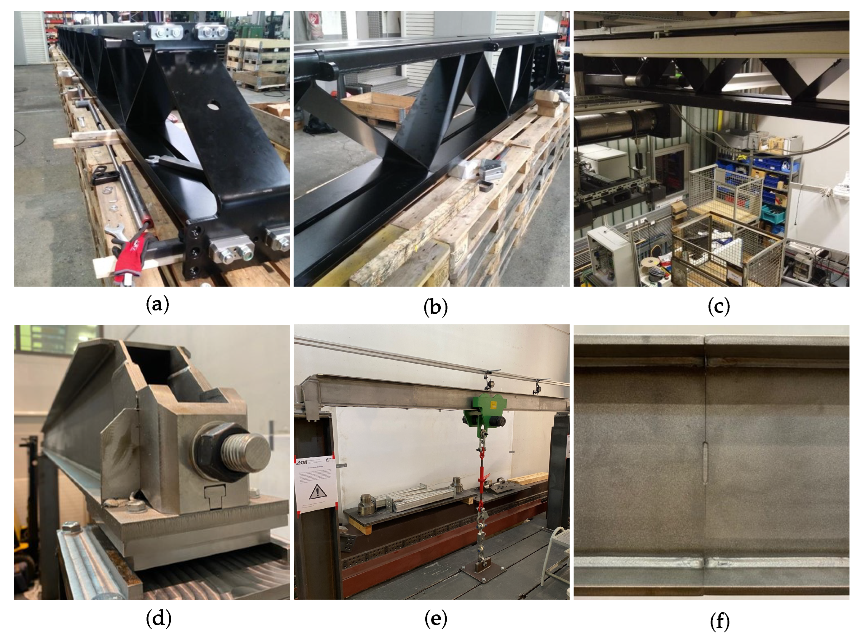
In addition, the setups of the prototypes are depicted in Figure 18. The upper three figures show the crane bridge in truss construction. Here, Figure 18a,b show a crane bridge with a span width of 12 m and a load capacity of 5 t. On the other hand, the crane bridge depicted in Figure 18c has a span width of 6.1 m and a load capacity of 3.2 t. Figure 18d–f show the crane bridge in box section design. As a first functional model, it has a span width of 3 m and is designed for a load capacity of 3 t.
For the first prototypes, the structures were also analyzed in FE analyses, and a detailed simulative study was carried out for the box section design in [26] and for the truss design in [25]. This shows that the Mises yield criterion was not exceeded at the critical points of the design and that no gaping occurs at the segment joints due to the applied pretension. Still, the aspect of buckling (i.e., the occurrence of negative eigenvalues in the stiffness matrix) with an increase in the required prestressing force is the design driving factor for the box section design in terms of a later practical use.
4.2. Potentials
As already previously pointed out, the novel bridge crane design concept offers several potentials. The most important include, in particular, manufacturing; however, there are further potentials, such as:
- Required work area;
- Handling of components;
- Decentralized production;
- Transportation;
- Lightweight design potential.
These are to be highlighted and explained in the following section as well. A major advantage of the segmented design are the dimensions of the components involved. Compared with conventional cranes, less working space has to be made available for their manufacturing. Furthermore, the design offers the advantage that the individual parts of the crane can be manufactured by conventional largely automated machinery. Another advantage of the smaller dimensions of the components is that they are easier to handle during production. Different processing stations have to be passed, including welding or painting, for example. In conventional systems, the crane bridge is designed as a single part, meaning that in-plant transport between the individual processing stations requires additional conveying equipment (e.g., another bridge crane for handling the loads) and a corresponding infrastructure. Due to the smaller dimensions of the components of the segmented design, transport between the processing stations is less challenging and can be carried out more quickly, for example, by using forklifts. In the conventional case, the entire crane bridge is assembled at one location and must be transported from there to the place of operation. In this context, the possibility of building the crane bridge from individual components made by conventional machinery can be used for decentralized production. This means that the entire crane bridge does not have to be manufactured at one location but by several manufacturers who may be located closer to the place of operation or have available production capacities. The entire process up to the assembly of the crane bridge can thus be faster. Furthermore, it is planned to manufacture the individual sheet metal elements by laser cutting and edging. In combination with automated welding processes, this is expected to provide the necessary accuracy. The motivation of the alternative approach mentioned at the beginning includes the transport of the individual parts. These are designed so that they can be transported on conventional conveying aids, such as EUR pallets, and loaded onto trucks with the aid of forklifts. This also makes transport to difficult-to-access terrain easier. This includes, for example, mining regions or areas with inadequate transport infrastructure. The applied pretension within the design allows for influence of the resulting stress and the deformation. Using the box section design as an example, optimization algorithms were developed in [26] on the basis of the concept presented in order to determine the geometric dimensions of the profiles so that the overall structure is of minimum weight, taking into account developed constraint functions for the design. A comparison with three reference cranes from [18] indicates that the box section design and the algorithms used have resulted in a weight saving of between 19% and 22% compared to the conventional cranes. The truss design tends to be of higher weight at this stage due to the large number of individual parts. Nevertheless, it should be mentioned that the two concepts have not yet been finalized; rather, they are the subject of ongoing research activities with a view to improving the mechanical aspects, the associated design strategies, and development of design rules. This also includes detailed investigations on the mechanical behavior considering different load cases in the framework of further FE analyses and real experiments.
4.3. Challenges
It turns out that the novel design concepts offer a number of benefits compared to conventional bridge crane systems. However, the concepts face further challenges, which are to be illustrated in the following and mainly cover:
- Mechanical issues;
- Costs;
- Acceptance of potential operators, customers.
As previously shown in Table 3, additional mechanical challenges have to be overcome in the context of segmented structures. These include in particular the weld seams, since the structure is by definition not capable of absorbing tensile stresses. For this reason, the frictional connection at the joints must be maintained at all times. This applies especially to the box section design; see Section 3.1. Furthermore, the area of axial load application is subject to high stresses. To compensate local stress increases, relief notches are provided to relieve the adjacent weld seams connecting the web plates to the bottom flange. A detailed design of the relief notch is the subject of current research and development work. In this context, a method will also be developed to monitor the applied prestressing force during operation. Maintaining the prestressing force is essential for the reliability of the structure, as it is the only way to provide the load-bearing capacity. Further research work covers the design of the joints in the box section design. Here, the previously defined serviceability has to be ensured in any case. For this reason, the development of an additional mechanically designed safety function is planned. A major challenge is the cost of the segmented design. The aim here is that the costs should not be particularly higher than for conventional crane systems, otherwise the competitiveness is not given. From this requirement, it is also already possible to determine a field of application for segmented cranes. These can only compete with box-type crane bridges, i.e., for spans of approx. 12m and more. A replacement of rolled I-shaped girders, on the other hand, seems unlikely due to the low production costs. Although the acceptance of potential users can be classified as a soft criterion compared to the mechanical challenges and the costs, it is nevertheless crucial for a successful market launch. For this reason, a future analysis of stakeholder management is to be considered as well.
5. Conclusions and Outlook
In this paper, an alternative construction method for designing crane bridges is presented and analyzed with respect to different aspects. The aim is here to assemble the crane bridge from standardized individual parts to form a plug-in structure and then to brace it using a tensile member that runs in the hollow profiles of the girder structure. Two concept ideas are presented as a reference: the crane bridge structure as a segmented truss and the structure consisting of segments in box section design. Both have in common that the structure is naturally not capable to absorb tensile stresses. For this reason, the segmented crane bridge is pretensioned by a tensile member to provide the load-bearing capacity. A key property of the prestressing force is the ability to influence the resulting deflection of the beam. This effect is specifically used in box section design, where the prestressing force is applied eccentrically to the centroid axis of the girder. Furthermore, compared to conventional bridge crane systems, new constraints arise that are not represented in the current design specifications. These include, for example, ensuring compressive stress in the bottom chord to prevent the girder from gaping at the joints. Both concepts are investigated and compared with each other in the course of a comparative study to identify current issues and further design improvements. Here, it further turns out that the novel design strategy offers advantages that cover not only simplified transport but also aspects of manufacturing. The smaller dimensions of the components involved facilitate handling during production. In addition, decentralized production of the parts is conceivable. However, the challenges of the novel concept relate primarily to the mechanical loads on the structure, such as elastic stability and stresses especially in the box section design, and the resulting costs, which must be only marginally higher than the manufacturing costs of a conventional crane system to achieve competitiveness. For this purpose, load capacities and spans for which box-type crane bridges are usually used are taken into account. Future research activities include the economic analysis of the application of these novel structures in bridge crane systems as well as the improvement of mechanical issues considering manufacturing-related aspects.
Author Contributions
Conceptualization, J.O.; methodology, J.O.; software, J.O. and K.J.B.; validation, J.O. and K.J.B.; formal analysis, J.O.; investigation, J.O.; resources, J.O. and K.J.B.; data curation, J.O. and K.J.B.; writing—original draft preparation, J.O. and K.J.B.; writing—review and editing, J.O. and K.J.B.; visualization, J.O. All authors have read and agreed to the published version of the manuscript.
Funding
This research received no external funding.
Data Availability Statement
Data are contained within the article.
Acknowledgments
The authors acknowledge support by the KIT-Publication Fund of the Karlsruhe Institute of Technology and would like to thank the reviewers for their detailed reading and helpful comments to improve the quality of the work.
Conflicts of Interest
The authors declare that they have no known competing financial interests or personal relationships that could have appeared to influence the work reported in this paper.
References
- Hong, K.S.; Shah, U.H.S. Dynamics and Control of Industrial Cranes; Advances in Industrial Control; Springer Nature: Singapore, 2019. [Google Scholar] [CrossRef]
- Griemert, R.; Römisch, P. Fördertechnik: Auswahl und Berechnung von Elementen und Baugruppen, 11th ed.; Springer Fachmedien: Wiesbaden, Germany, 2015. [Google Scholar] [CrossRef]
- Schweitzer, P.A. Fundamentals of Corrosion: Mechanisms, Causes, and Preventative Methods; Corrosion Technology; CRC Press: Boca Raton, FL, USA, 2009. [Google Scholar] [CrossRef]
- Dolan, C.; Hamilton, H. Prestressed Concrete: Building, Design, and Construction, 1st ed.; Springer: Cham, Switzerland, 2019. [Google Scholar] [CrossRef]
- Magnel, G. Prestressed Steel Structures. Struct. Eng. 1950, 28, 285–295. [Google Scholar]
- Ayyub, B.M.; Sohn, Y.G.; Saadatmanesh, H. Prestressed Composite Girders under Positive Moment. J. Struct. Eng. 1990, 116, 2931–2951. [Google Scholar] [CrossRef]
- Belletti, B.; Gasperi, A. Behavior of Prestressed Steel Beams. J. Struct. Eng. 2010, 136, 1131–1139. [Google Scholar] [CrossRef]
- Wadee, A.; Hadjipantelis, N.; Gardner, L.; Lozano-Galant, J. Stability of steel struts with externally anchored prestressed cables. J. Constr. Steel Res. 2020, 164, 105790. [Google Scholar] [CrossRef]
- Gosaye, J.; Gardner, L.; Wadee, M.A.; Ellen, M.E. Tensile performance of prestressed steel elements. Eng. Struct. 2014, 79, 234–243. [Google Scholar] [CrossRef]
- Gosaye, J.; Gardner, L.; Wadee, M.A.; Ellen, M.E. Compressive behaviour and design of prestressed steel elements. Structures 2016, 5, 76–87. [Google Scholar] [CrossRef]
- Hadjipantelis, N.; Gardner, L.; Wadee, A. Prestressed cold-formed steel beams: Concept and mechanical behaviour. Eng. Struct. 2018, 172, 1057–1072. [Google Scholar] [CrossRef]
- Hadjipantelis, N.; Gardner, L.; Wadee, M.A. Design of prestressed cold-formed steel beams. Thin-Walled Struct. 2019, 140, 565–578. [Google Scholar] [CrossRef]
- Aragón, F.; Goberna, M.; López, M.; Rodríguez, M. Nonlinear Optimization; Springer Undergraduate Texts in Mathematics and Technology; Springer International Publishing: Berlin/Heidelberg, Germany, 2019. [Google Scholar] [CrossRef]
- DIN EN 15011:2021-10; Cranes-Bridge and Gantry Cranes. Deutsches Institut für Normung e.V.: Berlin, Germany, 2021.
- DIN EN 13001-3-1:2012+A1:2013; Cranes-General Design-PArt 3.1: Limit States and Proof Competence of Steel Structure. Deutsches Institut für Normung e.V.: Berlin, Germany, 2015.
- DIN EN 13001-3-3:2014; Cranes-General Design-Part 3.3: Limit State and Proof of Competence of Wheel/Rail Contacts. Deutsches Institut für Normung e.V.: Berlin, Germany, 2015.
- ISO 22986:2007(E); Cranes-Stiffness-Bridge and Gantry Cranes. International Organization for Standardization: Geneva, Switzerland, 2015.
- Savkovic, M.; Bulatovic, R.; Gasic, M.; Pavlovic, G.; Stepanovic, A. Optimization of the box section of the main girder of the single-girder bridge crane by applying biologically inspired algorithms. Eng. Struct. 2017, 148, 452–465. [Google Scholar] [CrossRef]
- Qu, X.; Xu, G.; Fan, X.; Bi, X. Intelligent Optimization Methods for the Design of an Overhead Travelling Crane. Chin. J. Mech. Eng. 2015, 28, 187–196. [Google Scholar] [CrossRef]
- Sun, C.; Tan, Y.; Zeng, J.C.; Pan, J.S.; Tao, Y. The Structure Optimization of Main Beam for Bridge Crane Based on An Improved PSO. J. Comput. 2011, 6, 1585–1590. [Google Scholar] [CrossRef]
- Lagaros, N.; Manolis, P. Applied soft computing for optimum design of structures. Struct. Multidiscip. Optim. 2012, 45, 787–799. [Google Scholar] [CrossRef]
- Pavlovic, G.; Savkovic, M. Analysis and Optimization of the Main Girder of the Bridge Crane with an Asymmetric Box Cross-Section. Sci. Tech. Rev. 2022, 72, 03–11. [Google Scholar] [CrossRef]
- Su, S.; Qin, Y.; Yang, K. Structural optimization of unsymmetrical eccentric load steel box girder based on new swarm intelligence optimization algorithm. Int. J. Steel Struct. 2022, 22, 1518–1536. [Google Scholar] [CrossRef]
- Wang, J.; Yan, W.; Gui, X. Application of Matlab Optimization Tool Box on Sections of Prestressed Steel-Concrete Composite Box Girder. Adv. Mater. Res. 2011, 366, 177–180. [Google Scholar] [CrossRef]
- Bolender, S.; Oellerich, J.; Braun, M.; Golder, M. Skalierbarer modularer Brückenkranträger in Segmentbauweise. Logist. J. Proc. 2017, 1–8. [Google Scholar] [CrossRef]
- Oellerich, J. Fundamentals for the Dimensioning and Optimization of Prestressed Segmented Girders for Application in Bridge Crane Systems. Ph.D. Thesis, Karlsruhe Institute of Technology (KIT), Karlsruhe, Germany, 2021. [Google Scholar] [CrossRef]
- VDI 3655; Requirements on Flat Pallets for the Use in Mechanised and Automated Conveying and Storage Systems. VDI: Düsseldorf, Germany, 2008.
- Timoshenko, S.P.; Gere, J.M. Theory of Elastic Stability, 2nd ed.; Dover Civil and Mechanical Engineering; Dover Publications, Inc.: Mineola, NY, USA, 2009. [Google Scholar]
- von Tetmajer, L. Die Gesetze der Knickungs- und der zusammengesetzten Druckfestigkeit der technisch wichtigsten Baustoffe (Classic Reprint); Fb&c Limited: London, UK, 2018. [Google Scholar]
- O’Hanlon, J.F.; McCauley, M.E. Motion Sickness Incidence as a Function of the Frequency and Acceleration of Vertical Sinusoidal Motion. Aerosp. Med. 1974, 45, 366–369. [Google Scholar] [PubMed]
- Wächter, M.; Müller, C.; Esderts, A. Angewander Festigkeitsnachweis nach FKM-Richtlinie, 1st ed.; Springer Vieweg: Wiesbaden, Germany, 2017. [Google Scholar] [CrossRef]
- VDI 2230; Systematic Calculation of Highly Stressed Bolted Joint—Joints with One Cylindrical Bolt. VDI: Düsseldorf, Germany, 2016.
Figure 1.
Qualitative illustration of a conventional single-girder bridge crane.

Figure 2.
Conventional girder types for single-girder bridge cranes; (a) sectional girder in I-shaped design; (b) box section girder.
Figure 2.
Conventional girder types for single-girder bridge cranes; (a) sectional girder in I-shaped design; (b) box section girder.
Figure 3.
Functional design of the segmented truss design based on [25].
Figure 3.
Functional design of the segmented truss design based on [25].
Figure 4.
Front section view of the segmented truss construction, based on [25].
Figure 4.
Front section view of the segmented truss construction, based on [25].
Figure 5.
Hollow profile (a) and connecting block (b), based on [25].
Figure 5.
Hollow profile (a) and connecting block (b), based on [25].
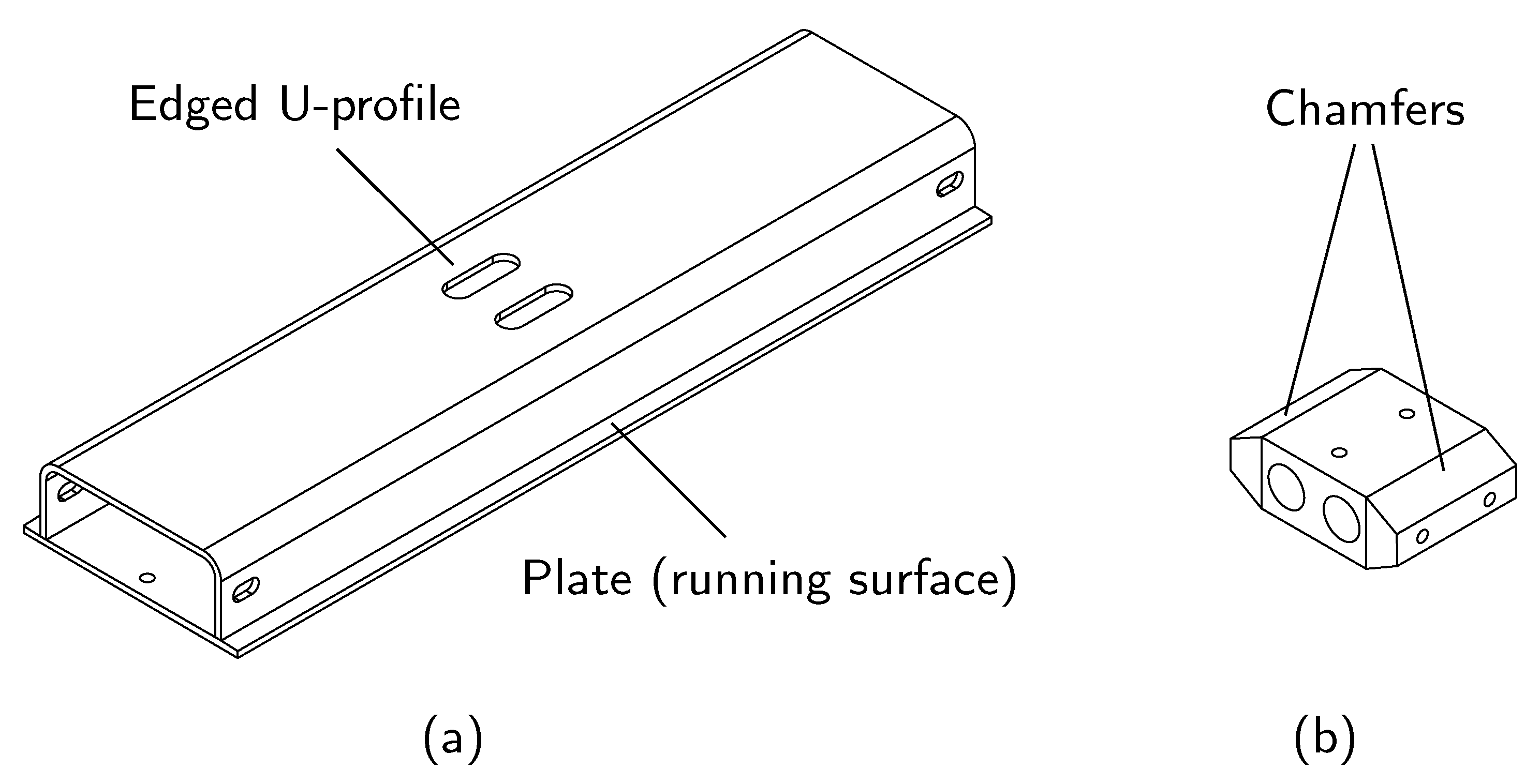
Figure 6.
Cross brace, based on [25].
Figure 6.
Cross brace, based on [25].
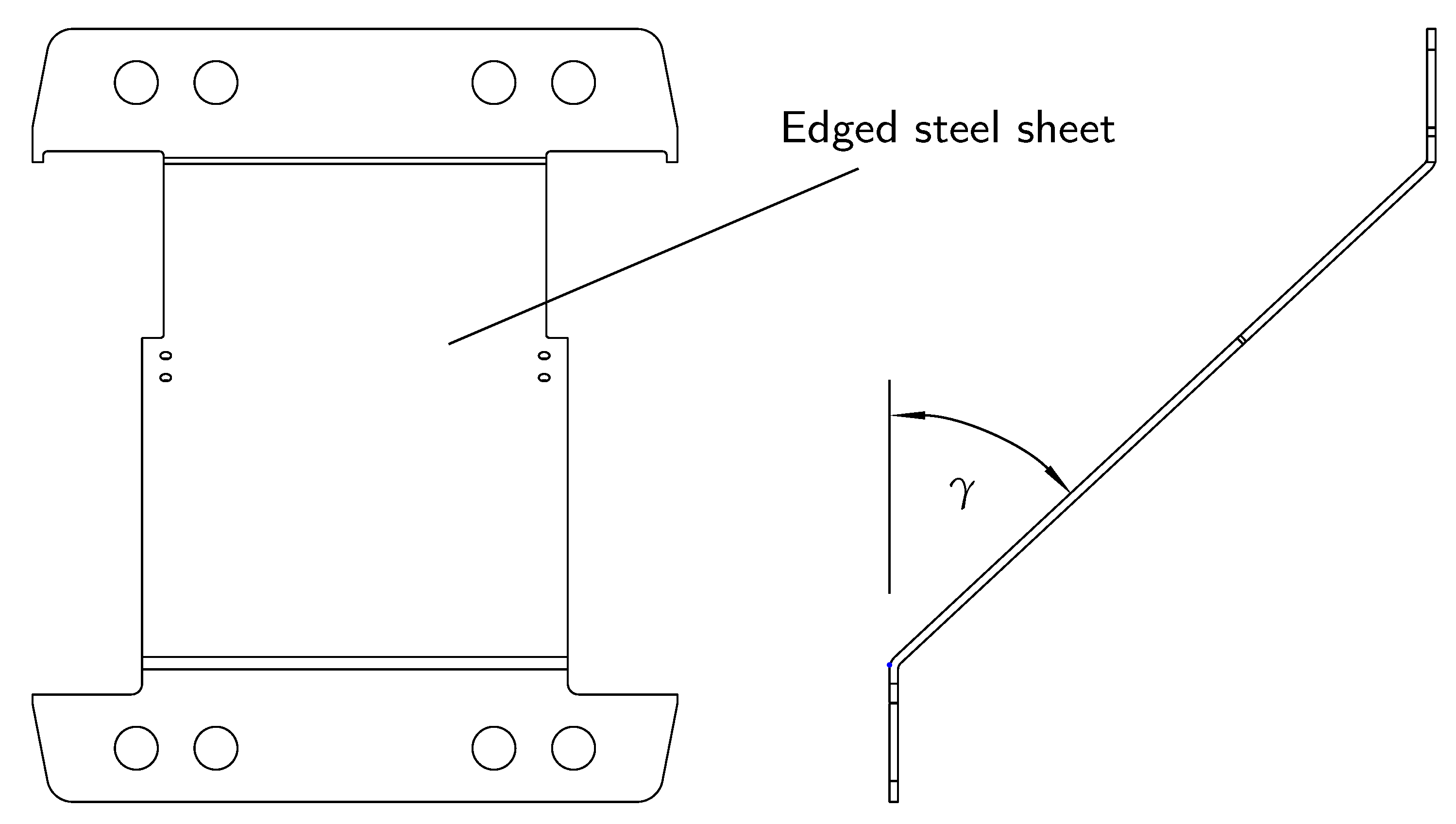
Figure 7.
Section view of the tensile member to be applied in the segmented truss design, based on [25].
Figure 7.
Section view of the tensile member to be applied in the segmented truss design, based on [25].

Figure 8.
Segmented truss design, detailed view [26].
Figure 8.
Segmented truss design, detailed view [26].

Figure 9.
Functional design of the segmented box section design [26].
Figure 9.
Functional design of the segmented box section design [26].

Figure 10.
Design of the main segment [26].
Figure 10.
Design of the main segment [26].
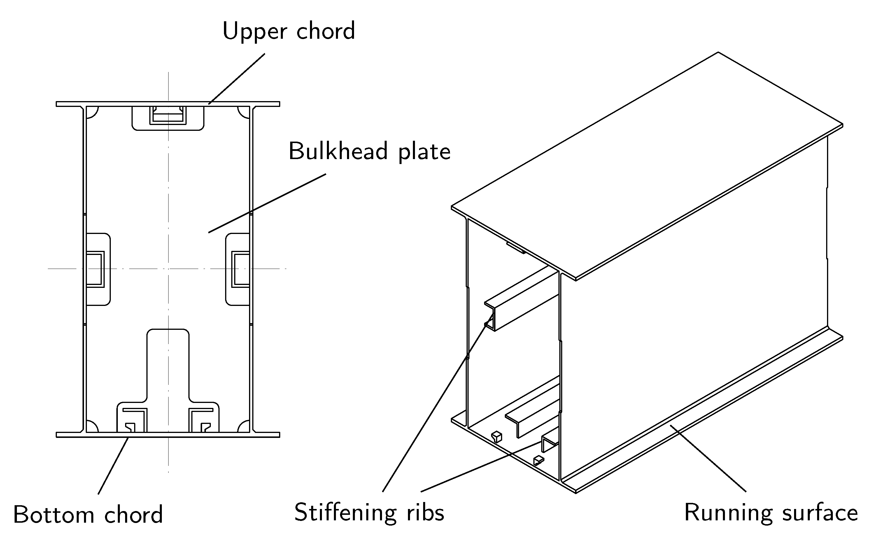
Figure 11.
Design of the preload segment [26].
Figure 11.
Design of the preload segment [26].
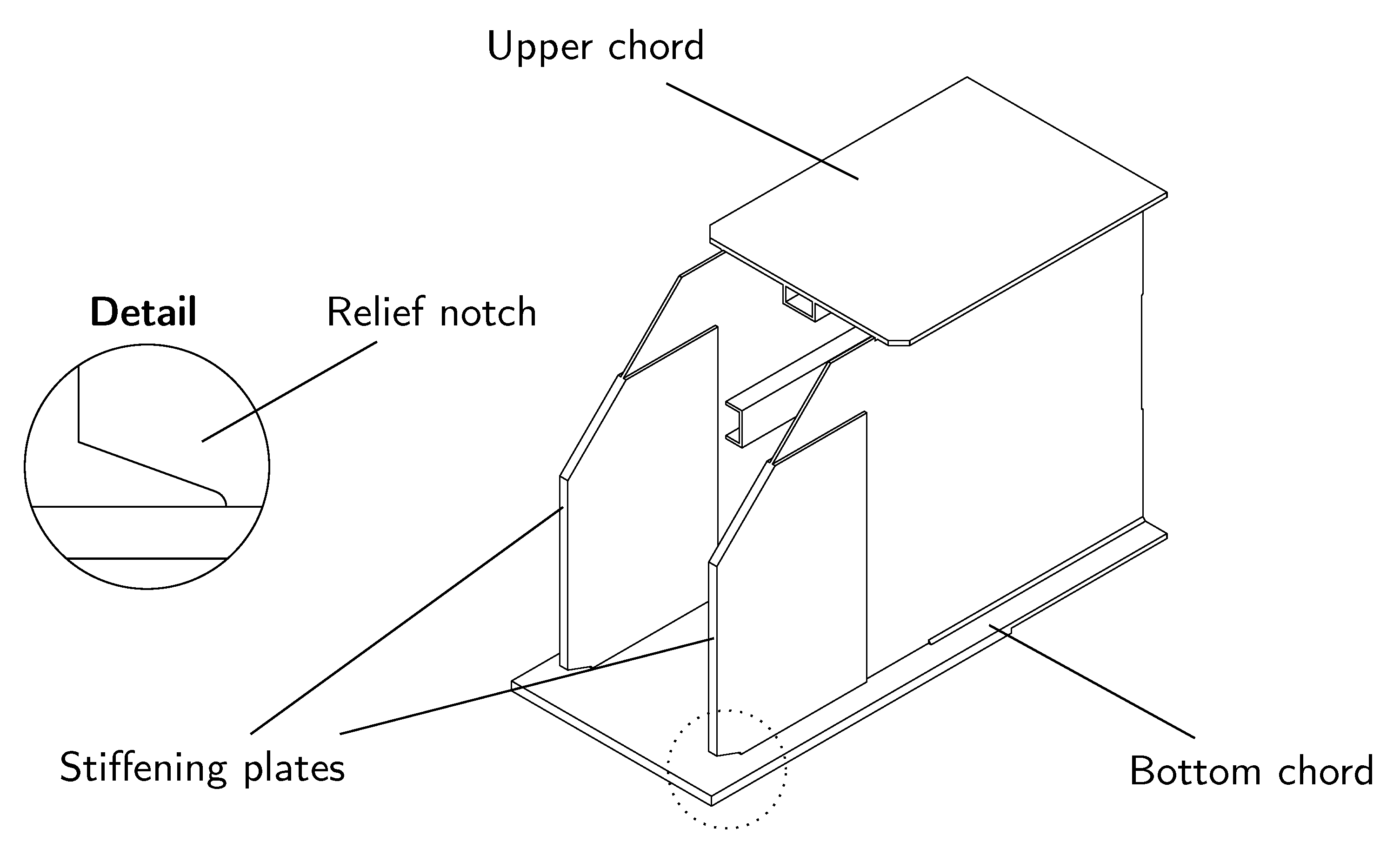
Figure 12.
Design of the stop piece (a) and the connecting element (b) [26].
Figure 12.
Design of the stop piece (a) and the connecting element (b) [26].
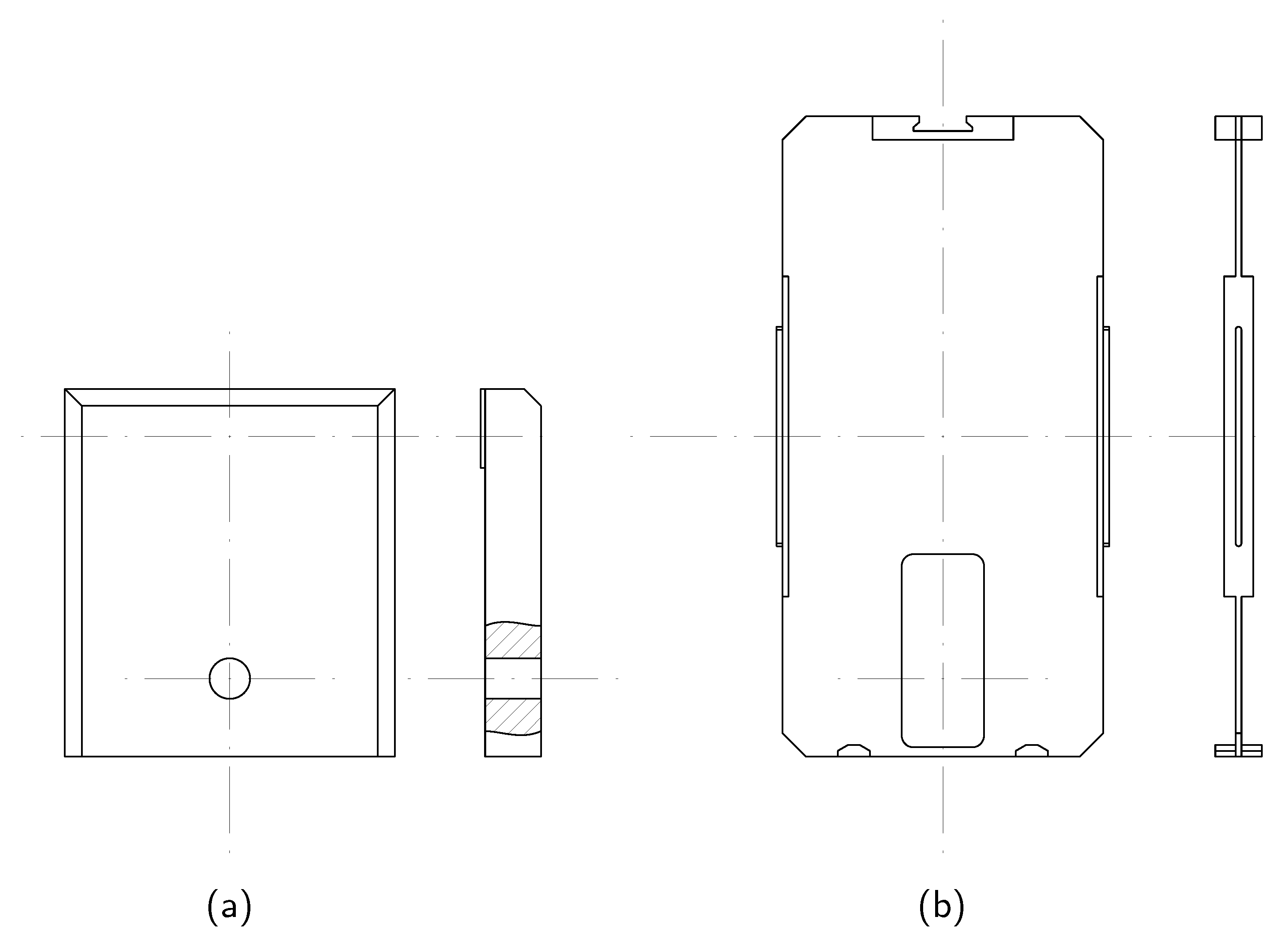
Figure 13.
Section view of tensile member to be applied in the box segmented section design [26].
Figure 13.
Section view of tensile member to be applied in the box segmented section design [26].

Figure 14.
Section view of the preload area [26].
Figure 14.
Section view of the preload area [26].
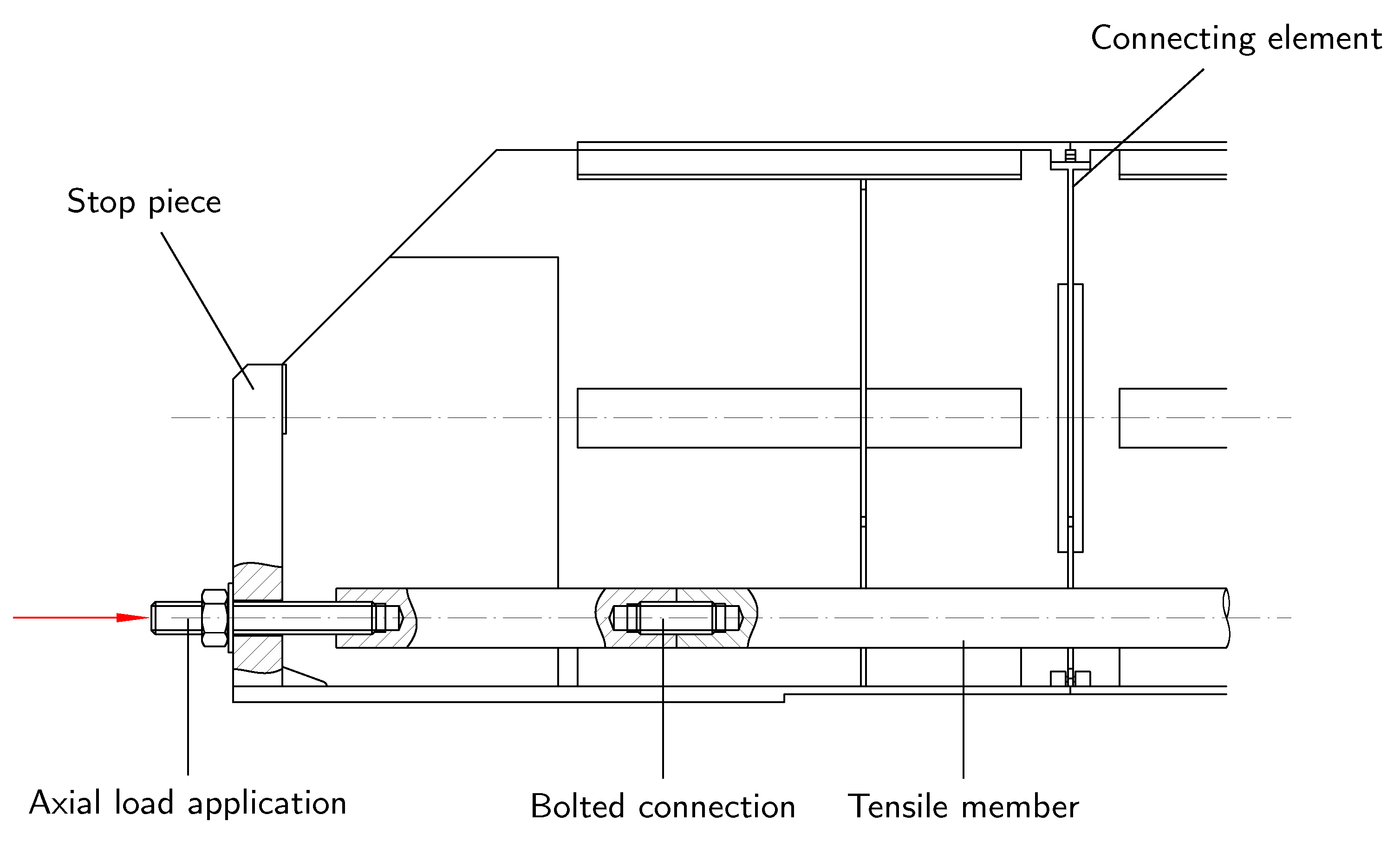
Figure 15.
Assembling the segmented structure in box section design [26].
Figure 15.
Assembling the segmented structure in box section design [26].

Figure 17.
Deflection of the segmented girder in box section design [26].
Figure 17.
Deflection of the segmented girder in box section design [26].
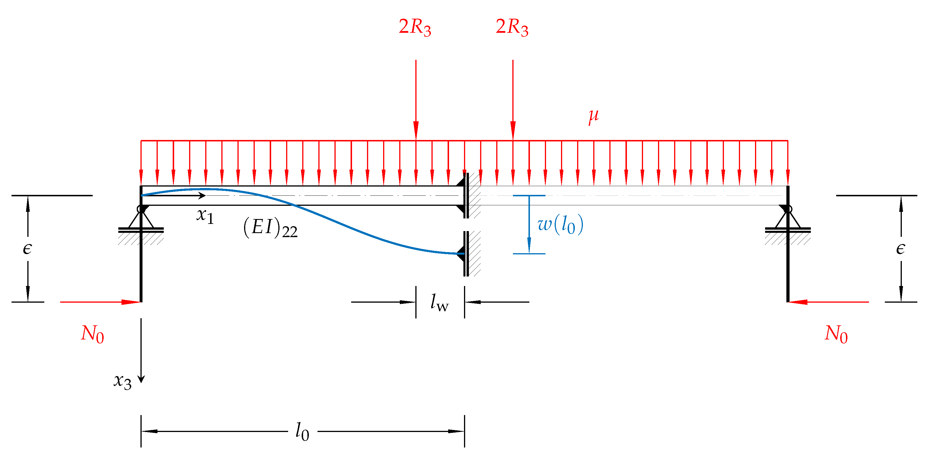
Figure 18.
Prototypes of the segmented bridge crane concepts: (a–c): Truss design, (d–f): Box design.
Figure 18.
Prototypes of the segmented bridge crane concepts: (a–c): Truss design, (d–f): Box design.

Table 1.
Resulting segmentation types based on [26].
Table 1.
Resulting segmentation types based on [26].
| Type | |||
|---|---|---|---|
| 1 | |||
| 2 | |||
| 3 | |||
| 4 |
Table 2.
Example configurations with regard to the underlying segmentation type.
| Type | ||||
|---|---|---|---|---|
| 4900 | 10 | 950 | 3 | |
| 5150 | 10 | 1200 | 2 | |
| 5500 | 11 | 1150 | 4 | |
| 6350 | 13 | 1200 | 1 |
Table 3.
Qualitative assessment and comparison of the truss design (TD) and the box section design (BD) with respect to defined criteria; the number of filled points represents the fulfillment of the respective criterion.
Table 3.
Qualitative assessment and comparison of the truss design (TD) and the box section design (BD) with respect to defined criteria; the number of filled points represents the fulfillment of the respective criterion.
| Criterion | TD | BD | Description |
|---|---|---|---|
| Small number of variants (individual components) | Compared to the BD, the TD uses a comparatively large number of different individual parts which are to be manufactured. | ||
| Low complexity of the design | The large number of individual parts in the TD results in them having to be precisely matched to one another during assembly. The BD uses less parts, but they are more complex to manufacture. | ||
| Usage of commercially available traveling trolley | Due to the necessary inner height of the hollow profiles of the TD, the use of a conventional trolley is not possible. In this case, a special design is required in which the chassis is adapted accordingly. A conventional trolley can be used for the BD. | ||
| Low manufacturing effort | The production of the individual parts of the TD is less complex compared to the welded segments in the BD. Although more individual processes are required (e.g., cutting, edging and welding), these are easier to implement. | ||
| Easy component handling | Due to the smaller dimensions of the TD components, they are easier to handle, i.e., they can be moved and mounted without additional equipment. The components of the BD, on the other hand, require additional handling equipment for larger dimensions. | ||
| Short assembly time | The large number of individual parts in the TD results in a longer assembly time. The assembly of the BD can be done faster, but this requires a safe handling of the additional handling equipment. | ||
| Low assembly effort | The smaller dimensions of the components in the TD allow them to be mounted more easily. The assembly of the components in the BD is more challenging and requires more effort. | ||
| Transportation on EUR pallets | Both concepts allow the transportation of parts on EUR pallets. | ||
| Small number of crucial weld seams | The weld seams on the TD are favorably positioned with regard to the load that occurs, since the wheel load is introduced directly into the web of the U-profile. In case of loss of the frictional force connection, however, the weld seam on the web plate of the bottom flange of the BD is subjected to particular stress risings at the joints. | ||
| Ensuring elastic stability | Both the web plates and the plates of the upper and bottom chord in the BD are exposed to high compressive stresses and can tend to buckle. For this reason, they must be designed accordingly. In the TD, on the other hand, the hollow U-profiles are designed robustly; only the compressive stresses in the web plates have to be taken into account separately. |
Disclaimer/Publisher’s Note: The statements, opinions and data contained in all publications are solely those of the individual author(s) and contributor(s) and not of MDPI and/or the editor(s). MDPI and/or the editor(s) disclaim responsibility for any injury to people or property resulting from any ideas, methods, instructions or products referred to in the content. |
© 2023 by the authors. Licensee MDPI, Basel, Switzerland. This article is an open access article distributed under the terms and conditions of the Creative Commons Attribution (CC BY) license (https://creativecommons.org/licenses/by/4.0/).
Share and Cite
MDPI and ACS Style
Oellerich, J.; Büscher, K.J. Application of Segmented and Prestressed Supporting Structures in Bridge Crane Systems: Potentials and Challenges. Appl. Syst. Innov. 2023, 6, 105. https://doi.org/10.3390/asi6060105
AMA Style
Oellerich J, Büscher KJ. Application of Segmented and Prestressed Supporting Structures in Bridge Crane Systems: Potentials and Challenges. Applied System Innovation. 2023; 6(6):105. https://doi.org/10.3390/asi6060105
Chicago/Turabian StyleOellerich, Jan, and Keno Jann Büscher. 2023. "Application of Segmented and Prestressed Supporting Structures in Bridge Crane Systems: Potentials and Challenges" Applied System Innovation 6, no. 6: 105. https://doi.org/10.3390/asi6060105