Article

3D Printing of Ceramic Elements with Q-Surface Geometry for the Fabrication of Protective Barrier

by
Semen V. Diachenko
1,2,*,
Andrey S. Dolgin
3,
Nikolai A. Khristyuk
1,2,
Lev A. Lebedev
1,4,
Lubov A. Nefedova
1,
Sergey B. Pavlov
5,
Kirill F. Merenkov
1,
Vladimir I. Ivkov
6 and
Alla N. Dmitrieva
1
1
JSC «Obykhovsky Zavod», Obykhovskoi Oboroni Av. 120, 192012 Saint-Petersburg, Russia
2
St. Petersburg State Institute of Technology, Technical University, Moskovsky Av. 24-26/49, 190013 Saint-Petersburg, Russia
3
Institute of Silicate Chemistry, Russian Academy of Sciences, Makarov Emb. 2, 199034 St. Petersburg, Russia
4
Ioffe Institute, Russian Academy of Sciences, Politekhnicheskaya St. 26, 194064 St. Petersburg, Russia
5
The Bonch-Bruevich Saint Petersburg State University of Telecommunications, Bol’shevikov Av. 22, 193232 St. Petersburg, Russia
6
JSC «ZRTO», Obykhovskoi Oboroni Av. 120, Lit. H, 192012 St. Petersburg, Russia
*
Author to whom correspondence should be addressed.
Ceramics 2023, 6(2), 912-921; https://doi.org/10.3390/ceramics6020053
Submission received: 14 February 2023 / Revised: 19 March 2023 / Accepted: 29 March 2023 / Published: 3 April 2023
(This article belongs to the Special Issue Composite Nanopowders: Synthesis and Applications)

Abstract

:
The work proposes the use of aluminum oxide-based ceramic objects with a TPMS-Q-surface geometry as elements of armor structures. The samples were produced using the SLA-DLP 3D printing method. The main properties of the sample were determined using physical-chemical analysis methods: apparent density ρap = 3.6 g/cm3, open porosity Popn = 8.5%, microhardness Hµ = 15.3 GPa, water absorption W = 2.4%, elastic modulus E = 405 GPa. The Stiglich criterion M = 1.72 EPa2·m3/kg, and the Shevchenko criterion K = 0.8.

1. Introduction

Currently, requirements for strength and mass characteristics of modern protective barrier constructions are continuously increasing, while the operating conditions of the products are becoming more aggressive. In addition to dynamic loads, they are subjected to various physical effects such as thermal, sound, and electromagnetic. Therefore, creating a material that is sufficiently strong, rigid, and meets the requirements of resistance to a complex of physical factors is a challenging task. However, this task can be solved by giving the construction a special form.
One of the oldest principles of classical mechanics establishes the relationship between the shape and structure/properties of a solid body: a change in shape leads to a change in its qualities, and sometimes to the emergence of new properties. A special type of cellular materials, namely triply periodic minimal surfaces [1], can be considered as a new form of materials. Materials with such geometry possess unique physico-mechanical properties, which allows them to be used as structural materials. In addition, they have a number of other properties, such as high specific strength and large deformational compactness.
The first examples of TPMS were surfaces described by Schwarz in 1865, as well as by his student E.R. Neovius in 1883. In nature, such surfaces are found in binary lipid layers, block copolymers, the structure of butterfly wings, and beetle shells, which combine low mass and in-creased strength [2]. These topologies are present in Fermi surfaces in solid bodies. Despite the fact that TPMS have been widely known since the mid-19th century, after the monumental work of Schwarz [3], practical interest from engineers and materials scientists in such surfaces only appeared in the late 20th century, since the production of objects and materials with TPMS geometry is only possible using additive technologies.
Before the intensive development of additive technologies, the use of cellular structures was quite limited, as classical subtractive production methods did not allow the production of structures with very complex topology. Achievements in additive manufacturing led to a paradigm shift in the design of functional components, allowing for the creation of structures with complex topology in order to reduce weight and increase the multifunctionality of end products. Therefore, these materials are now considered promising materials for various engineering applications. For example, they have the ability to absorb mechanical energy [4], can be used in heat transfer tasks [5], in high-load-bearing structures, biomedical implants [6] and other [7,8,9,10,11,12,13,14].
This study proposes to use the TPMS geometry for the manufacture of protective barriers—armor made of ceramic materials. Based on the dissociative theory of destruction developed by academician V. Ya. Shevchenko, it has been proven that under conditions of extremely high loading velocities, ceramic materials are the most effective. Currently, armor made precisely from ceramic materials such as aluminum oxide, silicon carbide, boron carbide, etc., has gained widespread use for passive protection of personnel and equipment in Russia and abroad [15,16,17]. Ceramic armor was first used by the US military during the Vietnam War in the 1970s. In the USSR, ceramic armor was first used in the military operation in Afghanistan in the 1980s. Since then, the use of ceramic armor by armies of different countries in combination with other materials to protect ground combat vehicles, ships, airplanes, and helicopters has been continuously growing.
Ceramics are generally considered to be materials obtained through thermal processing (sintering, hot pressing) of the main component—powders of inorganic substances. Oxide, carbide, boride, nitride and composite ceramics are used to make armor elements. High hardness, modulus of elasticity, melting/destruction temperature (at 2–3 times lower density), and preservation of strength during heating are important properties of ceramic materials that have made their use as armor compared to metals possible. This set of properties allows the use of ceramics for armor-piercing projectiles.
Structural ceramics consist of crystalline and amorphous phases, as well as free space—pores. The properties of these phases and porosity determine the mechanical properties of ceramic armor elements. It is known that with the decrease in the size of crystalline particles, the decrease in the amount of amorphous phase and porosity in ceramics, its strength and hardness increase [18]. In turn, high hardness combined with low impact viscosity determines the protective ability of ceramic armor. The typical technology for producing ceramic products is sintering at temperatures close to the melting temperature of the raw material, with pre-formed blanks. Sintered ceramics are characterized by the presence of porosity that deteriorates its mechanical properties. Reducing the amount of pores in ceramic products while maintaining high mechanical properties can be achieved by hot pressing of raw powders at high temperature.
A separate sector of promising armor elements can be identified as synthetic mineral alloys—siminalls. These are inorganic non-metallic materials consisting of oxides and the main component—silicon dioxide (SiO2). These materials are similar in composition to ceramics, but differ in production. Siminalls are primarily obtained as a result of melting natural stone raw materials or techno-waste with similar composition, rather than sintering. Siminalls are unique materials that combine the hardness and durability of natural stone. However, the material structure is aligned and interphase stresses in it are minimized. For example, work [19] has shown that siminalls have a high ability to dissipate mechanical energy upon collision with the striking element.
To evaluate the efficiency of ceramics as materials that resist mechanical dynamic loading, there are several criteria, such as the M. Ashley criterion [20], the V.S. Neshpor, A.L. Maistrenko, G.P. Zaitsev criterion [21], the J.J. Stiglitz criterion [17], the Sul-King Chang criterion [17], the J. and G. Quinn criterion [22], etc.
One of the first requirements for the suitability of a material as armor was proposed by J.J. Stiglitz, as a result of which his criterion became widely used [18]:
M = E H K ρ
where Hk—is the hardness according to Knoop, E—is the modulus of elasticity, and ρ—is the material density.
One of the modern armor-resistant criteria is the criterion proposed by V. Ya. Shevchenko [23,24]—the coefficient of relative penetration of the striker, which is based on the velocity of sound in the material:
K = l p l s t = ( ρ s t · V s t 2 ρ c e r · V c e r 2 ) 1 / 3
where lst and lp are the length of the striker and the depth of penetration, ρsteel and ρcer are the densities of the striker (in most cases steel) and barrier (ceramics), Vst and Vcer are the longitudinal sound velocity in the striker and barrier.
Table 1 presents the properties of ceramic materials from [25] compared to those of armor steel, and the criteria are calculated according to Equations (1) and (2).
From Table 1, it can be seen that materials based on boron carbide have the highest protective properties. Their widespread use is limited by the high cost of the pressing method. Therefore, boron carbide tiles are used when there is a significant reduction in the weight of armor protection, for example, for protection of seats and automatic control systems of helicopters, crew and landing. Titanate diboride, which has the highest hardness and modulus of elasticity, is used to protect against heavy armor-piercing and armor-penetrating tank projectiles. For mass production, relatively cheap aluminum oxide is most promising. Ceramics based on it are used for the protection of human life, ground and naval military equipment.
Currently, there are many constructions of ceramic armor elements. Each type undergoes “field” tests before mass production in a series. Despite the diversity of types, one can describe the general mechanism of impact of a projectile (striker, bullet) with armor and the processes that occur during impact [24,26,27]: the projectile collides with the ceramic surface and transfers its kinetic energy; in the ceramic, a wave of stresses arises: tensile, compressive, and shear stresses, the magnitude of which depends on the characteristics of the projectile; in the ceramic, a system of cracks forms; the ceramic transmits the stresses to the projectile, the projectile deforms or is destroyed; the projectile or its fragments, as they are embedded in the ceramic, reduce their speed through energy transfer mechanisms; the energy is transferred to the body of a person or the body of the technology.
Modern systems for protection against small-caliber weapons typically consist of layers of ceramics and a metallic or composite base [28]. A typical armor system for individual protection includes an outer layer of fiber-reinforced composite (FRC) with a polymer matrix, ceramic plates, and an FRC backing [29]. Aluminum is commonly used as a base for protection of vehicles [30]. Most ceramic armor technologies still focus on designs that are assemblies of flat, secured tiles or a single composite polygonal tile on different backings or casings. In the 1990s, a variety of ceramic armor based on discrete, individual ceramic elements embedded in a flexible matrix appeared. The mechanism of reflection here is complemented by the non-homogeneity of the cross-section, where a multitude of ceramic elements of different shapes and designs not only shatter the projectile, but also bring an additional rotational effect that enhances the armor characteristics [29]. One of the armor component designs containing ceramics is described in patent [31], where the ceramic armor component is made in the form of a regular hexagonal prism with its lateral faces having a curved shape relative to the vertical axis.
The works of Academician V. Ya. Shevchenko and colleagues [32,33,34] demonstrate high effectiveness of TPMS geometry samples as energy-absorbing materials for passive protection. Samples with such geometry efficiently dissipate impact energy. For instance, [35] shows that multiphase materials based on TPMS with a cellular structure have increased crack resistance and can absorb mechanical energy at much higher deformation values compared to traditional materials. Additionally, the use of TPMS allows for reducing surface energy and surface tension, and therefore residual stresses. As a result, in recent decades, there has been a significant increase in interest in such structures, both from mathematicians and materials scientists.
In this work, a model sample with Q-surface geometry—TPMS (Figure 1) is proposed as a protective element. To obtain a 3D model of TPMS with the specified geometry, an implicit modeling approach was used in the “Rhinoceros” software together with the “Grasshopper” plugin in accordance with equation [36]:
(cosx − 2cosy)·cosz − √3•sinz·(cos(x − y) − cosx) + cos(x − y)·cosz = 0.
The sample was fabricated suspension from photopolymer resin and aluminum oxide (Al2O3) by 3D printing. The manufactured sample has a cube shape with an edge size of approximately 30 mm and a mass of 34.2 g. As shown in Figure 1, the sample has numerous interpenetrating openings that are distributed throughout the volume, which significantly increases the free surface energy and reduces the mass-dimensional properties of the product.

2. Production Technology

The manufacturing technology of the TPMS element and production organization is based on a variant of the stereolithography method—DLP, the principle of which consists in the layer-by-layer formation of the part through the interaction of UV radiation and photopolymer resin with a filler. A serial 3D printer “Admaflex 130” was used in the work [37]. The choice of the printer is determined by the unique design system of the details, which occurs not in a resin bath, but in a thin layer applied to the polymer film. On the platform, which is sequentially raised to the height of the layer in the range of 15–100 microns, the detail is constructed. The delivery of new material is achieved by moving the polymer film along the work table. After illuminating a certain surface of the print material, excess material is removed from the film and transferred to the printer piping system to the beginning of the cycle for applying a new layer of material to the film. This cycle is repeated until the full product is constructed according to the digital model. The schematic principle of the printer’s operation is shown in Figure 2 (arrows indicate the movement of raw material).
The samples were printed with a layer height of 30 μm. After printing, the parts were subjected to a two-stage thermal treatment: annealing to remove the organic binder (up to 1300 °C), and sintering (≤1700 °C). The shrinkage, claimed by the manufacturer, varies from 25 to 35% in both directions.

3. Research Method

The structure and morphology of the surface, as well as the elemental composition of the printed product, were studied using the Tescan Vega 3 scanning electron microscope with the «AZtec X-act». The accelerating voltage was 20 kV, and the probe current was 8∙10−10 A.
The phase composition was determined on the X-ray diffractometer «Rigaku SmartLAB 3». X-ray diffraction shots were taken with Mo-Kα radiation with a high-speed energy dispersion position-sensitive detector «Dtex Ultra 250» in the 2θ angle range 5–45° with a focus on Bragg-Brentano with an angular velocity of 2°/min. Decryption of diffraction patterns was carried out in the software environment «Crystallographica Search-Match» using the “ICCD PDF2” database.
The apparent density was determined in accordance with GOST 2409-2014, and samples were saturated with water at near boiling temperature.
The modulus of elasticity (Young’s modulus) of the samples was determined by the resonant method of acoustic frequency control on the instrument «Zvuk-130».
Microhardness (Hμ) was measured on the microhardness tester «PMT-3» with a Vickers diamond pyramid under a load of 1.962 N in accordance with GOST 9450-76.
Roughness parameters were determined in accordance with GOST 2789-73 on the profilometer «MarSurf PS1».

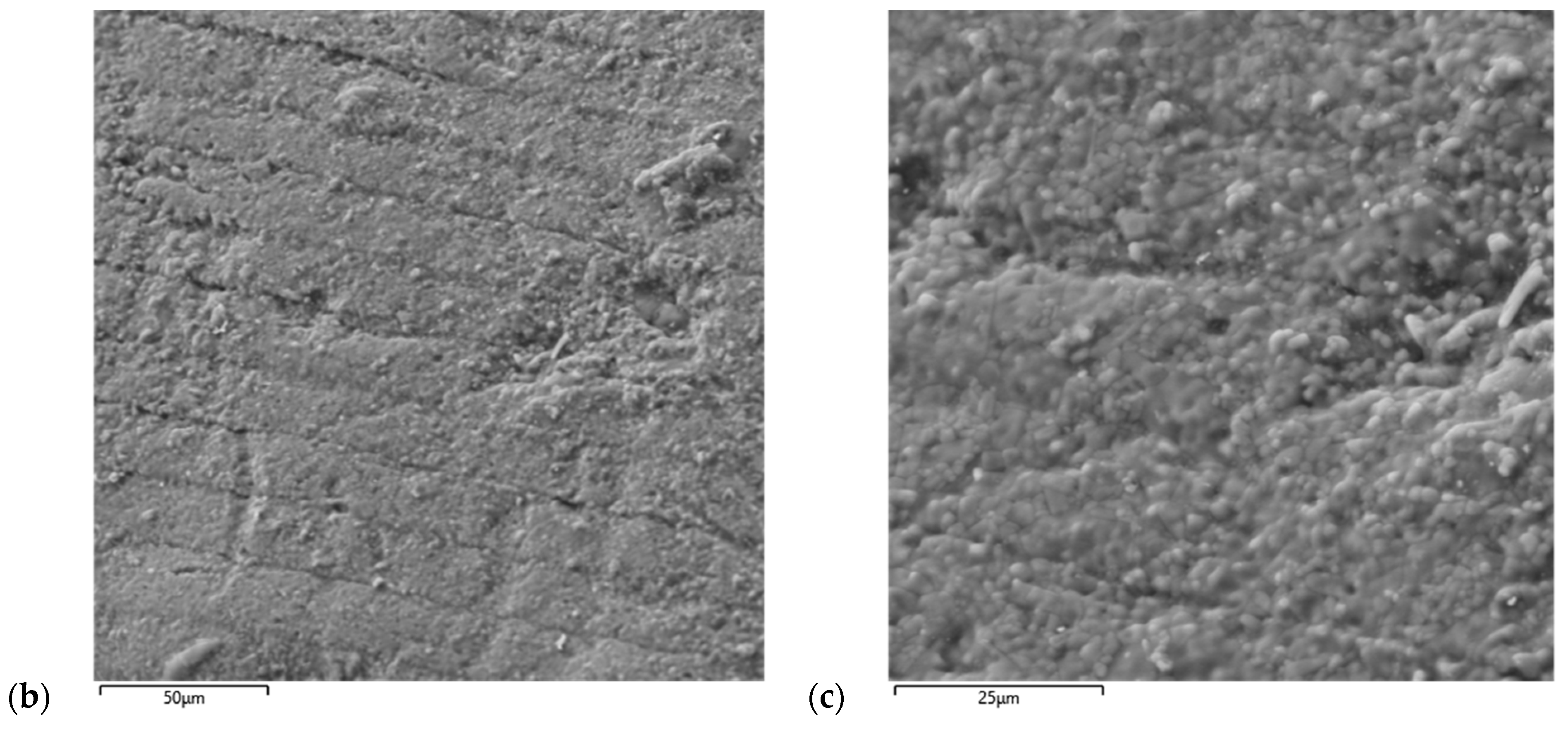
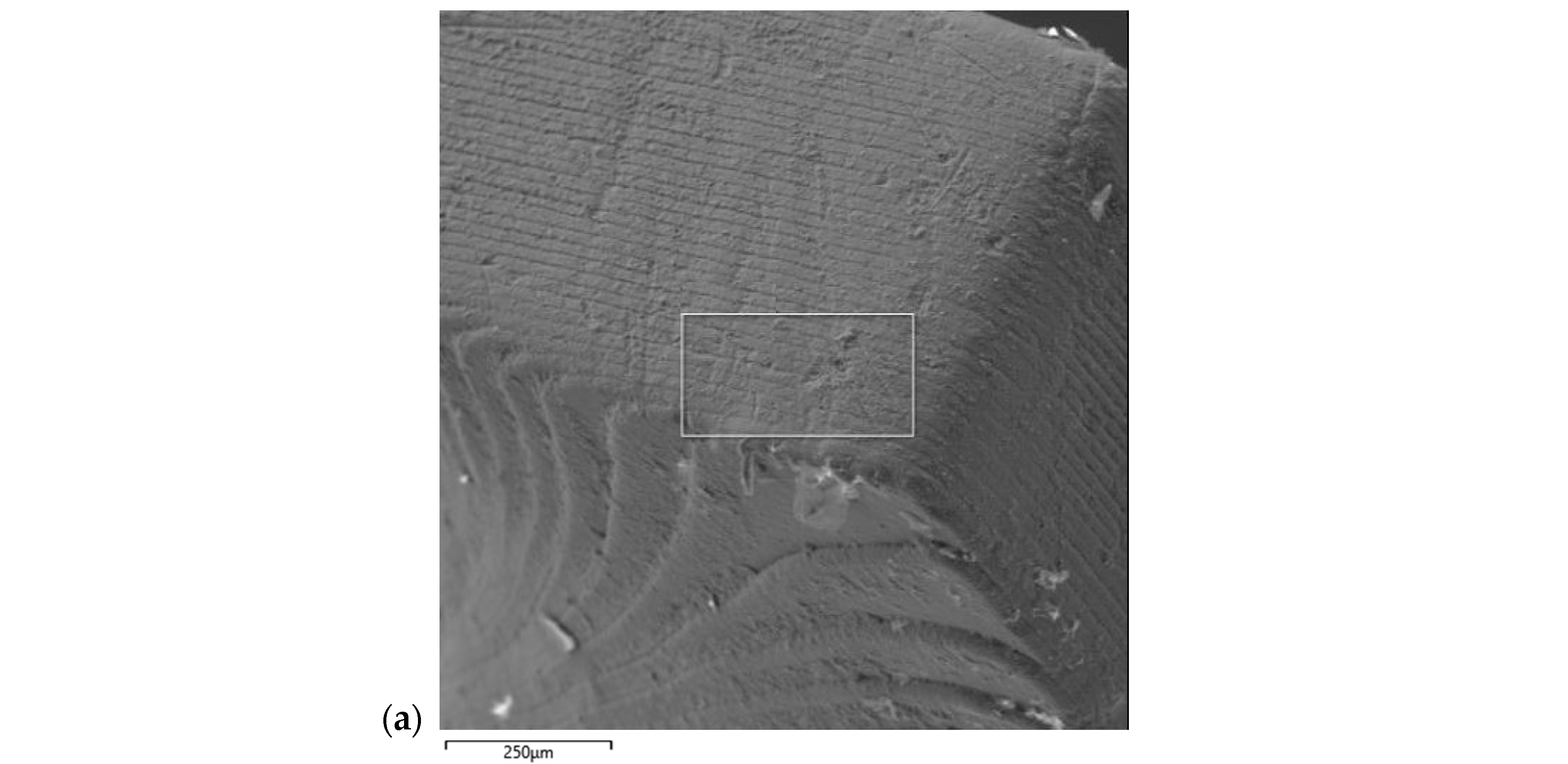
4. Discussion of Results

According to the data from scanning electron microscopy (Figure 3a,b), the structure of the sample was analyzed at various levels. In particular, the size of the layer that was sintered at once when building the 3D printer blank was determined, which after sintering amounted to l ≈ 20 μm, indicating a 33% material shrinkage. The microstructure of the layers is characterized by sintered grains (with an estimated size of about 5 μm) with low inter-granular porosity. The grains tend to be isotropic, although in some cases, there is a large spread of grain sizes from 2 μm to 12 μm. This can be explained by the absence of sintering additives or a low content of sintering additives that do not affect the rate of grain growth. From the analysis of microphotographs, it can be concluded that the sample does not have macroscopic building defects and has layers of uniform thickness, minor defects—cracks, colorings, sintering defects were not detected, which in total indirectly indicates high mechanical properties of the printed product. Based on the micro X-ray spectroscopic analysis (the highlighted area in Figure 3a), it can be concluded that it is practically pure aluminum oxide, the detected Fe and Si impurities indicate surface contamination, the presence of Na is a characteristic feature of aluminum oxide obtained by the Bayer method (Table 2). According to XRD data, the sample consists of corundum (PDF № 10-173), and no other impurities have been identified.
The apparent density, open porosity, and water absorption were determined by the hydrostatic weighing method. The results are shown in Table 3. It also indicates the density of corundum and the total porosity.
The modulus of elasticity and sound velocity were measured using the resonant method of acoustic frequency control of natural vibrations on the « Zvuk-130» device and were 405 GPa and 10,600 m/s, respectively. The microhardness (Hµ) of the sample according to Vickers was 15.3 GPa. The surface roughness parameter Ra on various sections without mechanical processing was—upper surface: 0.5…1.5 μm, side surface: 0.9…2.0 μm.
When comparing TPMS manufactured by DLP method from different manufacturers and solid ceramic made of corundum, some features of the sample can be identified. From Table 4, it is evident that the “Admatec” sample has relatively high micro-hardness, sound propagation speed, and elastic modulus, with lower values of density and layer thickness. The hardness of ceramics mainly depends on the quality, particle size of the original powder, and sintering conditions, so to improve this parameter, optimal particle size and sintering conditions should be selected in the future. The studied sample has high mechanical properties, but also has a maximum total porosity, which has both a positive impact, by reducing the mass characteristics of the final product, and also a negative impact, by reducing its strength properties.
Probably, significant mechanical properties are ensured by low porosity in the volume of the material, as 87% of pores are on the surface of the ceramic sample based on the results of porosity determination. Based on available data, calculations of armor resistance criteria (M, K) were made for the entire TPMS sample and corundum material using Equations (1) and (2).
For the convenience of calculating the M criterion, a replacement of characteristics has been made from existing data (it is noted in work [39] that instead of the hardness according to Knoop in (1), it is possible to use the more common hardness according to Vickers). If the dimensionality of this criterion is transformed, it is possible to obtain a value measured in [GPa]. Based on this dimensionality, it can be characterized as the acceleration of effort (the speed of change in the force velocity during the interaction of the striker with the obstacle). In other words, the higher this indicator is for a material, the larger changing loads it can prevent, and thus perform energy dissipation during high-speed loading. As can be seen, the value of the criterion is high for the sample being studied in the series of manufacturers and may tend to the value for solid corundum when selecting the corresponding 3D printing mode.
Based on Equation (2), the calculation of the K criterion for the materials presented allows them to be compared by the magnitude of sound velocity and material density in terms of resistance to dynamic loading when ceramics interact with a striker, in this case made of steel. Since all the mechanical energy of the striker is expended on the destruction (dissociation) of the material, the smaller the value of K, the higher the energy dissipation of the load at high-speed deformation and the smaller the depth of the cavity formed in the protective barrier. It is obvious that if the barrier is made of steel, then K = 1. Table 4 shows that for the sample under investigation, the K criterion is the smallest of those presented and tends in value to materials such as SiC and B4C, which are respectively more reliable than solid corundum, not due to the nature of the material, but primarily to the macrostructure—the geometry of the TPMS.

5. Scope of Application

From the processes of interaction between the striker and the armor element, it is possible to identify the obvious main task of armor elements—reducing the amount of energy transmitted to the protected subject. This task can be solved by increasing the energy dissipation during bullet contact with the armor element, the structure of which can act as a damper that absorbs the forced vibrations of the system by combining hard (brittle) materials with plastic ones. Usually, composite armor is a multilayered system consisting of a breaking-deflecting layer—discrete ceramic elements, for example, in the form of hexagonal solid prisms [31], linked together by a matrix based on polymer material; a retarding layer made of strong and plastic material, such as aluminum alloy, and an outer layer of fiber-reinforced composite. Each layer performs a specific task. For example, the polymer-based bonding fills the cavities between adjacent elements of ceramic material, and in the event of an impact, it prevents the spread of cracks and also ensures a guaranteed gap between the crushing-deflecting and retaining layers, thus allowing for an increase in bullet energy dissipation. Additionally, the polymer-based bonding may include nanoscale particles with special physical properties, such as reflective, scattering, or absorbing electromagnetic radiations.
Using the presented ceramic TPMS as an element of the crushing and deflecting layer, it is necessary to assemble a barrier matrix from similar elements. To do this, it is necessary to treat the surface (closing external pores) and fill all the free space of the openings with a polymer composition to increase protective properties, reduce fragility, and prevent destruction with fatal consequences. As such a polymer binder, a rubber-like polyurethane can be used, or, for example, a super-strong material—polydicyclopentadiene, which was developed by the United Scientific Research and Development Center, a subsidiary of Rosneft [40]. The domestically developed polymer is resistant to deformation and is characterized by increased resistance to mechanical stress and aggressive environments in the temperature range of −60… +185 °C. Initially, this material is used for the manufacture of casing pipes in well construction. However, it is also known that the material has high impact resistance, so a small object with an initial velocity of approximately 300 m/s and an energy of ≥300 J leaves a depression in the polydicyclopentadiene element with a depth no more than 3 mm. The polymer itself providing protective properties, combined with a ceramic product made with TPMS geometry, for example, in the form of indented hexagonal prisms, can significantly increase energy dissipation and make a breakthrough in the technology of armor production.

6. Conclusions

Based on the results of the study and taking into account the advantages of similar ceramic products with TPMS geometry, such as low mass and high mechanical properties compared to solid ceramic elements, it can be concluded that this type of ceramic element has high potential and suitability for use in armor and production. The Q-surface geometry element is competitive among other TPMS geometries and can be used as passive armor for military and law enforcement personnel. Using traditional ceramic manufacturing technology and protective barrier design skills, this work can be directed towards finding the optimal TPMS geometry and material selection for improved performance characteristics.

Author Contributions

Conceptualization, S.V.D. and L.A.L.; Methodology, L.A.N., S.B.P. and A.N.D.; Software, L.A.L.; Validation, A.S.D.; Formal analysis, A.S.D. and K.F.M.; Investigation, S.V.D., A.S.D. and N.A.K.; Resources, S.B.P. and K.F.M.; Data curation, V.I.I. and A.N.D.; Writing – original draft, S.V.D.; Visualization, V.I.I.; Supervision, L.A.N.; Project administration, S.V.D. and S.B.P. All authors have read and agreed to the published version of the manuscript.

Funding

The modeling of samples was carried out as part of the Russian science foundation (RSF) project No. 20-73-10171 “Next-Generation Energy-Absorbing Materials Based on Gradient Cellular Structures”. The samples were manufactured under government contract 0081-2022-0001.

Institutional Review Board Statement

Not applicable.

Informed Consent Statement

Not applicable.

Data Availability Statement

Not applicable.

Acknowledgments

The authors express gratitude to the company “i3D” represented by Rodin M.V. for their assistance in completing this work.

Conflicts of Interest

The authors declare no conflict of interest.

References

  1. Lord, E.A.; Mackay, A.L.; Ranganathan, S. New Geometries for New Materials; Cambridge University Press: Cambridge, UK, 2006. [Google Scholar]
  2. Hasegawa, H.; Tanaka, H.; Yamasaki, K.; Hashimoto, T. Bicontinuous microdomain morphology of block copolymers. I. Tetrapod-network structure of polystyrene-polyisoprene diblock polymers. Macromolecules 1987, 20, 1651–1662. [Google Scholar] [CrossRef]
  3. Gibson, L.J.; Ashby, M.F. Cellular Solids Structure and Properties, 2nd ed.; Energy Absorption in Cellular Material; Chapter 8; Cambridge University Press: Cambridge, UK, 1997; pp. 309–344. [Google Scholar] [CrossRef]
  4. Păcurar, R.; Păcurar, A.; Petrilak, N.B. Finite element analysis to predict the mechanical behavior of lattice structures made by selective laser melting technology. In Applied Mechanics and Materials; Trans Tech Publications: Bäch, Switzerland, 2014; pp. 231–235. [Google Scholar]
  5. McKown, S.; Shen, Y.; Brookes, W.K.; Sutcliffe, C.J.; Cantwell, W.J.; Langdon, G.S.; Nurick, G.N.; Theobald, M.D. The quasi-static and blast loading response of lattice structures. Int. J. Impact Eng. 2008, 35, 795–810. [Google Scholar] [CrossRef]
  6. Chu, C.; Graf, G.; Rosen, D.W. Design for additive manufacturing of cellular structures. Comput. Aided Des. Appl. 2008, 5, 686–696. [Google Scholar] [CrossRef] [Green Version]
  7. Rosen, D.W. Computer-aided design for additive manufacturing of cellular structures. Comput. Aided Des. Appl. 2007, 4, 585–594. [Google Scholar] [CrossRef]
  8. Meza, L.R.; Das, S.; Greer, J.R. Strong, lightweight, recoverable three-dimensional ceramic nanolattices. Science 2014, 345, 1322–1326. [Google Scholar] [CrossRef] [Green Version]
  9. Santorinaios, M.; Brooks, W.; Sutcliffe, C.; Mines, R. Crush behaviour of open cellular lattice structures manufactured using selective laser melting. WIT Trans. Built Environ. 2006, 85, 481–490. [Google Scholar]
  10. Ravari, M.K.; Kadkhodaei, M.; Badrossamay, M.; Rezaei, R. Numerical investigation on mechanical properties of cellular lattice structures fabricated by fused deposition modeling. Int. J. Mech. Sci. 2014, 88, 154–161. [Google Scholar] [CrossRef]
  11. Ponche, R.; Hasco, J.-Y.; Kerbrat, O.; Mognol, P. A new global approach to design for additive manufacturing. In Additive Manufacturing Handbook; CRC Press: Boca Raton, FL, USA, 2017; pp. 169–180. [Google Scholar]
  12. Tancogne-Dejean, T.; Spierings, A.B.; Mohr, D. Additively-manufactured metallic micro-lattice materials for high specific energy absorption under static and dynamic loading. Acta Mater. 2016, 116, 14–28. [Google Scholar] [CrossRef]
  13. Schaedler, T.A.; Jacobsen, A.J.; Torrents, A.; Sorensen, A.E.; Lian, J.; Greer, J.R.; Valdevit, L.; Carter, W.B. Ultralight metallic microlattices. Science 2011, 334, 962–965. [Google Scholar] [CrossRef]
  14. Deshpande, V.S.; Fleck, N.A.; Ashby, M.F. Effective properties of the octet-truss lattice material. J. Mech. Phys. Solids 2001, 49, 1747–1769. [Google Scholar] [CrossRef] [Green Version]
  15. Grigoryan, V.A.; Kobylkin, I.F.; Marinin, V.M.; Chistaykov, E.N. Materials and Protective Structures for Local and Individual Booking; Radio Software: Moscow, Russia, 2008; 406p. [Google Scholar]
  16. GOST 34286-2017; Armored Clothing. Classification and General Technical Requirements. Rosstandart: Moscow, Russia, 2019.
  17. Garshin, A.P.; Gropyanov, V.M.; Zaitsev, G.P.; Semenov, S.S. Ceramics in Mechanical Engineering; JSC Nauchtekhlitizdat Publishing House: Moscow, Russian, 2003; 384p. [Google Scholar]
  18. Kobylkin, I.F.; Selivanov, V.V. Materials and Structures of Light Armor Protection; Textbook; MSTU im. N. E. Bauman: Moscow, Russia, 2014; 191p. [Google Scholar]
  19. Ignatova, A.M.; Artemov, A.O.; Zignatov, M.N.; Sokovikov, M.A. Methods for studying the dissipative properties of synthetic mineral alloys during high-speed penetration. Fundam. Res. Tech. Sci. 2012, 145–150. [Google Scholar]
  20. Crouch, J.G. Introduction to armor materials. Sci. Armor Mater. 2017, 1, 33. [Google Scholar]
  21. Neshpor, V.C.; Zaitsev, G.P.; Dovgal, E.J. Armour ceramics ballistic efficiency evaluation. In Ceramics: Charting the Future, Proceedings of the 8th. CIMTEC, Florence, Italy, 28 June–4 July 1994; Vincenzini, P., Ed.; Techna S.R.L.: Milano, Italy, 1995; pp. 2395–2401. [Google Scholar]
  22. Quinn, J.B.; Quinn, G.D. On the Hardness and Brittleness of Ceramics. Key Eng. Mater. 1997, 132–136, 460–463. [Google Scholar] [CrossRef]
  23. Shevchenko, V.Y.; Oryshchenko, A.S.; Perevislov, S.N.; Sil’nikov, M.V. Sound Waves Could be the Secret to Better Armour; Springer Nature: Berlin, Germany, 2021. [Google Scholar]
  24. Shevchenko, V.Y.; Oryshchenko, A.S.; Perevislov, S.N.; Sil’nikov, M.V. About the Criteria for the Choice of Materials to Protect Against the Mechanical Dynamic Loading. Glass Phys. Chem. 2021, 47, 281–288. [Google Scholar] [CrossRef]
  25. Rogov, V.A.; Solovyov, V.V.; Kopylov, V.V. New Materials in Mechanical Engineering; Textbook; RUDN: Moscow, Russia, 2008; 324p. [Google Scholar]
  26. Karandikar, P.G.; Evans, G.; Wong, S.; Aghajanian, M.K.; Sennett, M. A review of ceramics for armor applications. Adv. Ceram. Armor IV 2009, 29, 163–175. [Google Scholar]
  27. Woodward, R.L.; Gooch, W.A.; O’Donnell, R.G.; Perciballi, W.J.; Baxter, B.J.; Pattie, S.D. A study of fragmentation in the ballistic impact of ceramics. Int. J. Impact Eng. 1994, 15, 605–618. [Google Scholar] [CrossRef]
  28. Gooch, W.A. Overview of the development of ceramic armor technology: Past, present and the future. Adv. Ceram. Armor VII Ceram. Eng. Sci. Proc. 2011, 32, 193–213. [Google Scholar]
  29. Van Es, M.; Beugels, J.; van Dingenen, J. Development of Dyneema/ceramic hybrids for SAPI inserts. In Proceedings of the Personal Armour Systems Symposium 2002—PASS 2020, The Hague, The Netherlands, 18–22 November 2002; pp. 163–168. [Google Scholar]
  30. Gahr, M.; Heidenreich, B. Biomorphe SiSiC-Keramiken fur den Einsatz im Ballistischen Schutz; DKG; Deutsches Zentrum fur Luftund Raumfahrt: Stuttgart, Germany, 2005; Volume 82, pp. 125–129. [Google Scholar]
  31. Kamenskikh A., S.; Kormushin, V.A.; Kalgin, A.N.; Bogdanov, V.V.; Zyryanov, K.A.; Medvedko, V.S.; Medvedko, O.V.; Days, H.A.; Mukhin, V.V.; Markov, V.N. Ceramic Armour Element and Composite Armour on Its Basis. RU2459174C1, 20 August 2012. [Google Scholar]
  32. Shevchenko, V.Y.; Sychev, M.M.; Lapshin, A.E.; Lebedev, L.A. Ceramic materials with the triply periodic minimal surface for constructions functioning under conditions of extreme loads. Glass Phys. Chem. 2017, 43, 605–607. [Google Scholar] [CrossRef]
  33. Diachenko, S.V.; Lebedev, L.A.; Sychov, M.M.; Nefedova, L.A. Physicomechanical Properties of a Model Material in the Form of a Cube with the Topology of Triply Periodic Minimal Surfaces of the Gyroid Type. Technical physics. Russ. J. Appl. Phys. 2018, 63, 984–987. [Google Scholar] [CrossRef]
  34. Balabanov, S.V.; Makogon, A.I.; Sychev, M.M.; Evstratov, A.A.B.; Regazzi, A.; Lopez-Cuesta, J.M. 3D Printing and Mechanical Properties of Polyamide Products with Schwartz Primitive Topology. Technical physics. Russ. J. Appl. Phys. 2020, 65, 211–215. [Google Scholar]
  35. Sychov, M.M.; Lebedev, L.A.; Diachenko, S.V.; Nefedova, L.A. Mechanical properties of energy-absorbing structures with triply periodic minimal surface topology. Acta Astronaut. 2018, 150, 81–84. [Google Scholar] [CrossRef]
  36. Schnering, H.G.; von Nesper, R. Nodal surfaces of Fourier series: Fundamental invariants of structured matter. Z. Phys. B Condens. Matter. 1991, 83, 407–412. [Google Scholar] [CrossRef]
  37. Available online: https://admateceurope.com/admaflex-technology (accessed on 22 February 2022).
  38. Samsonov, G.V.; Borisova, A.L.; Zhidkova, T.G. Physico-Chemical Properties of Oxides: Handbook; Metallurgizdat: Moscow, Russia, 1978; 471p. [Google Scholar]
  39. Kharchenko, E.F.; Composite, E.A.F. Textile and Combined Armor Materials; JSC TSNIISM: Moscow, Russia, 2013; 294p. [Google Scholar]
  40. Afanasiev, V.V.; Dolgina, T.M.; Bespalova, N.B. Dicyclopentadiene Metathesis Polymerisation Catalyst, Prepartion Method Thereof and Polymerisation Method. RU2008148502/04A, 10 December 2008. [Google Scholar]
Figure 1. General view of the fabricated sample with Q-surface geometry.
Ceramics 06 00053 g001
Figure 2. Diagram of 3D printer. (Reprinted/adapted with from Ref. [37]. Copyright 2013, copyright Admatec).
Ceramics 06 00053 g002
Figure 3. Micrographs of the lateral surface of TPMS at various magnifications: (a) 70×, (b) 360×, (c) 900×.
Ceramics 06 00053 g003aCeramics 06 00053 g003b
Table 1. Properties of impact-resistant ceramic.
Materialρ, g/cm3HK, GPaE, GPaM, EPa2·m3/kg (EN/s2)K
Boron carbide hot pressed
B4C
2.5530.04505.300.77
Titanate diboride hot pressed TiB24.5033.05704.180.72
Silicon carbide SiC3.1021.04102.780.80
Aluminium oxide sintered Al2O33.9918.04041.820.83
Armor steel7.813.52100.0941.00
Table 2. Results of chemical analysis.
ElementAlOFeSiNa
Content, % w.57.738.82.20.80.5
Table 3. Sample Properties.
TPMSρap, g/cm3* ρ, g/cm3Popn, %Pt, %W, %
Q—surface3.603.998.539.772.37
* density of pure aluminium oxide [38].
Table 4. Comparison of properties of TPMS different production.
Fabricatorρap, g/cm3l, μmPt, %Hμ, GPaVs, m/sE, GPaM, EPa2·m3/kg (EN/s2)K
Prodways3.76835.7612.295003391.100.85
3D CERAM3.79835.128.899503751.420.82
Lithoz3.90402.2617.710,4504251.840.80
Admatec3.60209.7715.310,6004051.720.80
Corundum [38]3.99--≥20-4042.030.83
Disclaimer/Publisher’s Note: The statements, opinions and data contained in all publications are solely those of the individual author(s) and contributor(s) and not of MDPI and/or the editor(s). MDPI and/or the editor(s) disclaim responsibility for any injury to people or property resulting from any ideas, methods, instructions or products referred to in the content.

