Article

An Anode-Supported Solid Oxide Fuel Cell (SOFC) Half-Cell Fabricated by Hybrid 3D Inkjet Printing and Laser Treatment

Institute of Solid State Chemistry and Mechanochemistry SB RAS, 630128 Novosibirsk, Russia
*
Author to whom correspondence should be addressed.
Ceramics 2023, 6(3), 1384-1396; https://doi.org/10.3390/ceramics6030085
Submission received: 31 May 2023 / Revised: 16 June 2023 / Accepted: 26 June 2023 / Published: 30 June 2023

Abstract

:
A NiO-10YSZ/10YSZ half-cell for anode-supported solid oxide fuel cells (SOFCs) was fabricated using 3D inkjet printing and layer-by-layer laser treatment of printing compositions followed by thermal sintering by a co-firing method. The optimal granulometric composition and rheological characteristics of the printing compositions to fabricate the NiO-10YSZ (60:40 wt.%) anode support, NiO-10YSZ (40:60 wt.%) anode functional layer (AFL), and 10YSZ electrolyte were determined. Effects of the pore former and laser post-treatment on the morphology of the as-prepared anodes for the manufacture of SOFC anode supports were studied, and the optimum laser exposure for hybrid 3D printing was determined. A mechanism of influence of the exposure of laser post-treatment on the morphology of the NiO-10YSZ anode supports has been proposed. The mass content of 10YSZ and the number of layers were shown to affect the surface microstructure and the thickness of the thin-film electrolytes deposited on the surface of the anode supports. The hybrid inkjet 3D printing offers great opportunities as it allows a one-pot procedure to fabricate a NiO-10YSZ/10YSZ SOFC half-cell for SOFC anode supports.

1. Introduction

Currently, due to the environmental pollution resulting from energy production from fossil fuels, the search for alternative sources of energy is of great scientific interest [1]. In this regard, hydrogen has become an important fuel due to a number of significant advantages, such as high specific energy, environmental safety of combustion products, and the possibility of producing it locally [2,3]. Solid oxide fuel cells (SOFCs), generating energy by the oxidation of hydrogen-containing fuels with oxygen, can also be considered renewable energy sources using hydrogen [4]. SOFCs consist of a gas-tight ceramic electrolyte with ionic conductivity located between a porous anode and a cathode [5]. SOFCs have a number of significant advantages, such as high efficiency (60–65%), a wide range of fuels that can be used due to the relatively high chemical stability of the oxide systems, lower costs for internal reforming of hydrogen-containing fuel, and the option of not using expensive catalysts such as platinum or ruthenium [6,7].
However, despite the above advantages of SOFCs, their commercial application is difficult due to a great need to develop a scalable and universal method for producing SOFCs of complex shapes in order to increase the electrode/electrolyte interface [8,9]. At present, there are several traditional methods to fabricate SOFC functional elements. Thus, screen printing is one of them, and it is simple, efficient, and versatile. However, it has a low resolution, it cannot be used to print on curved or three-dimensional surfaces, and it is not well suited for printing complex designs [10,11]. Chemical vapor deposition [12] and pulsed laser deposition [13] are well-suited to produce stretchable thin-film electrodes and electrolytes of complex design; however, they are expensive due to the use of complex equipment. Therefore, it can be concluded that the development of a versatile method that allows the fabrication of both thick porous and thin gas-tight functional layers is of great practical importance and relevance.
In recent years, additive manufacturing technologies (AT) have increasingly been used in various energy sectors to improve the characteristics of the materials and products produced therefrom [14]. Additive manufacturing technologies are becoming more frequent in the fabrication of complete SOFCs and their individual functional layers [14,15]. The use of AT can significantly reduce the cost of the final product (by reducing energy and material consumption), and it allows the manufacturing of high-precision elements with complex product geometry [16,17].
There are a number of studies reported on the 3D printing of SOFC anodes using various approaches. Thus, the ink containing precursors of oxide anode materials [18,19] and ceramic inks [20,21] was used for inkjet printing. The method of inkjet printing using ceramic printing compositions is cost-effective, easily scalable, and allows precise control of the shape, size, and morphology of the printed object [20,22]. Microextrusion or robocasting has also been used for the 3D printing of a SOFC anode based on the NiO/YSZ ceramic composite [23,24,25]. In general, microextrusion has the same advantages as inkjet printing. It is important to note that, due to the slow printing speed, the fabrication of supporting anodes or electrolytes by these additive manufacturing methods is significantly difficult.
As to supporting electrolytes used to manufacture a first generation of SOFCs, they are produced by stereolithography [26,27,28] or the ceramics extrusion process [29,30]. Due to the high resolution, stereolithography allows the fabrication of products of complex shapes [31]. In addition, stereolithography has such advantages as high printing speed and low cost of printers. However, when using stereolithography for manufacturing the supporting electrolytes, it has a number of significant drawbacks, such as a significant shrinkage of the supporting electrolyte during sintering [28]. Apart from that, stereolithographic 3D printers are much more expensive to operate due to both the high cost of the UV-curable resin and the regular replacement of resin tanks [31]. The ceramic extrusion process has also been used to produce supporting electrolytes for SOFCs [29].
Inkjet printing is also used to form a thin-layer electrolyte on an anode support for the fabrication of a second generation of SOFCs [32,33]. Inkjet printing combined with an optimized sintering procedure allows the production of thin (5–30 µm), dense electrolyte layers with good adhesion and a defect-free, dense structure with excellent electrical performance. For example, Esposito et al. [32] fabricated a 1.2 μm thin, dense, and gas-tight SOFC electrolyte exhibiting a close-to-theoretical open circuit voltage and a peak power density of more than 1.5 W∙cm−2 at 800 °C.
Thus, we can conclude that, currently, there are no appropriate approaches to 3D printing allowing the successful production of both thin gas-tight electrolytes and supporting porous anodes. In this work, a layer-by-layer approach to fabricate the anode support, anode functional layer (AFL), and electrolyte by hybrid inkjet printing, followed by layer-by-layer selective laser treatment, was carried out. The use of laser treatment to produce high-temperature electrochemical devices allows for full automation and flexibility of the production processes. The precise adjustment of the main parameters of laser irradiation allows precise control of the penetration depth of laser light, size, and temperature in the area of its impact. In addition, laser treatment ensures high production efficiency and low economic costs [34]. The unique capabilities of laser and inkjet printing allow precise control of the porosity and thickness of the layers and a one-pot procedure to fabricate SOFCs with a complex gradient microstructure.

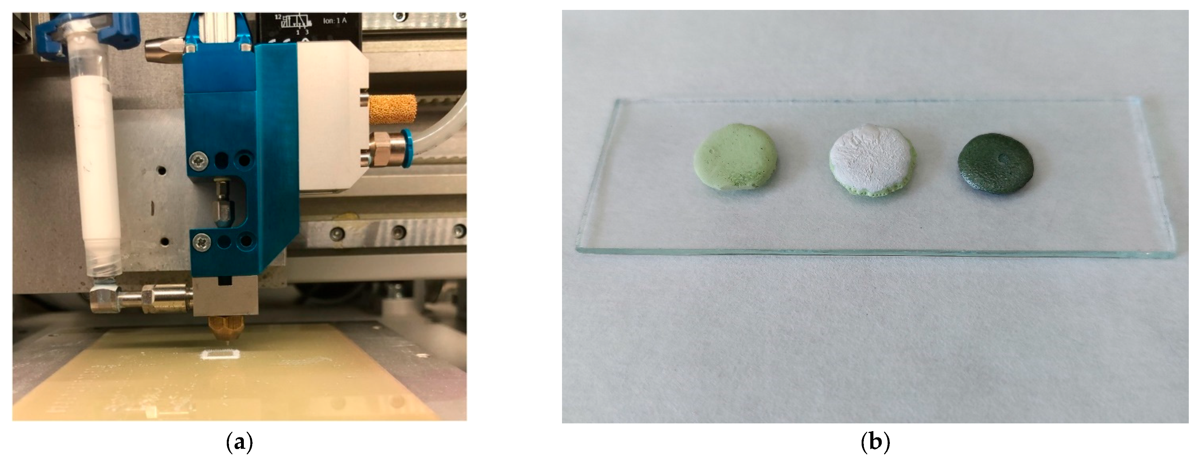
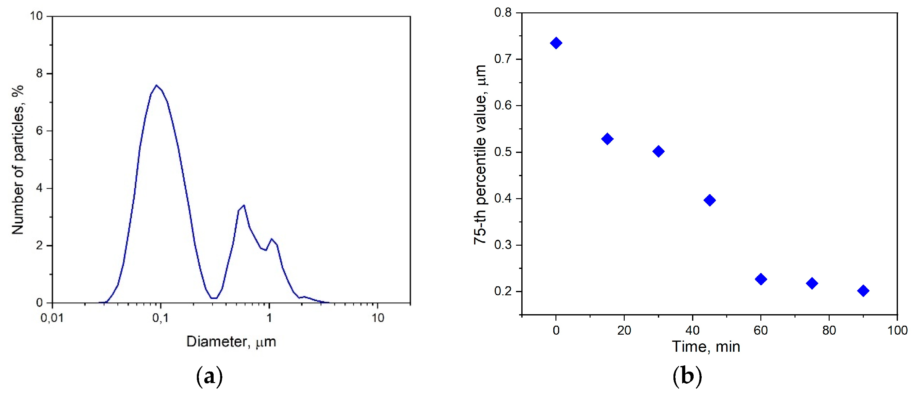
2. Materials and Methods

Nickel(II) oxide NiO (≥99.5%, SOFCMAN, Ningbo, China), yttria-stabilized zirconia 10 mol %, 10YSZ (Neohim LLC, Moscow, Russia), dipropylene glycol monobutyl ether DPGBE (Sigma–Aldrich, Saint Louis, MO, USA), polyvinyl butyral PVB (Acros Organics, Antwerp, Belgium), dibutyl phthalate DBF (Sigma–Aldrich, Saint Louis, MO, USA), and graphite (Sigma–Aldrich, Saint Louis, MO, USA) were used as received without further purification.
To prepare the NiO/10YSZ (60:40) composite material, nickel(II) oxide and 10YSZ were milled and homogenized in a laboratory-submerged ball mill (VMA-Getzmann, Reichshof, Germany) using yttria-stabilized zirconia 8 mol %, 8YSZ balls (dballs = 1.2 mm). The powders were ball-milled and homogenized in ethanol for 1 h at 5000 rpm and at a powder:ethanol:balls volume ratio of 1:1.5:2. The as-prepared slurry was kept in a drying box at 80 °C until completely dry.
To prepare the paste, PVB and DBP were dissolved in DPGBE with stirring and heating at 70 °C and then placed in a laboratory-submerged ball mill with milling balls made of yttria-stabilized zirconia YSZ8 (dballs = 0.6 mm). Composite powder was added to the paste and dispersed at 5000 rpm for 2 h; then, the paste was separated from the milling balls. To prepare the paste with a pore former, the powder was dispersed in an organic binder for 1.5 h at 5000 rpm; then, the speed was reduced to 1000 rpm, and a pore-former graphite was added and stirred for 0.5 h.
To prepare anode printing compositions, PVB and DBF were dissolved in DPGBE under stirring at a temperature of 70 °C. The as-prepared organic binder was then placed in a laboratory-submerged ball mill with 8YSZ balls (dballs = 0.6 mm), followed by the addition of NiO/10YSZ composite material to the mixture at a composite-to-binder weight ratio of 60/40 or 20/80. The mixture was dispersed at 5000 rpm for 1.5 h, then the speed was reduced to 1000 rpm, and pore-former graphite was added to the suspension, followed by stirring for 0.5 h. Then the paste was separated from the milling balls and used to print the NiO/10YSZ AFL and for anode support fabrication.
To print NiO/YSZ anodes, a hybrid laboratory inkjet 3D printer with the possibility of laser post-treatment of layers was used, which can use various dispensing systems for low-viscosity and high-viscosity compositions to control the layer thickness and shape of the final sample [35]. All experiments on printing were carried out using a pneumatic pulse valve with a nozzle diameter of 0.25 mm (Nordson Corporation, Erkrath, Germany; Westlake, OH, USA). Laser sintering of the printed layers using a fiber laser operating at a wavelength of 1.064 μm in a pulsed-intermittent mode was carried out in a single-pass mode with variable laser power. The duration and frequency of the laser pulse were 4 ns and 250 kHz, respectively; the average power varied in the range of 0.45–2.7 W. The printed samples were sintered at a temperature of 1400 °C for 2 h.
The printing of NiO/10YSZ (60:40 wt%) anode support, NiO/10YSZ (40:60 wt%) anode functional layer, and 10YSZ electrolyte was carried out using a hybrid laboratory inkjet 3D printer with the option of laser post-treatment of the layers according to the published procedure [35,36]. For joint sintering of the anode and electrolyte layers, a modified co-firing technique was used, which allows a temperature gradient inside the sample to be eliminated and controls the shrinkage of the individual layers. The latter allows for reducing the distortion of the structure [37]. The general scheme of the printing unit of a hybrid inkjet printer is shown in Figure 1a. The samples formed at different stages of co-firing technique are shown in Figure 1b. The NiO/10YSZ (60:40 wt%) anode support and NiO/10YSZ (40:60 wt%) anode functional layer were successively printed on the 3D printer. The resulting two-layer structure was sintered in a furnace at a temperature of 1100 °C for 1 h. Then, the YSZ electrolyte layer was printed, followed by sintering the layer at a temperature of 1350 °C for 1 h.
The morphology of the samples was analyzed using a Hitachi 3400N scanning electron microscope (Hitachi, Tokyo, Japan). The paste viscosity was measured using a Brookfield DV3T-RV viscosimeter (Brookfield Engineering Labs, Middleborough, MA, USA) with the cone/plate geometry at 25 °C. The granulometric composition of the samples was analyzed using a SALD-7500 nanolaser particle analyzer (SHIMADZU Corporation, Kyoto City, Japan). The contents of the pores in the sample were determined by means of ImageJ software (ImageJ 1.53k) using SEM images.

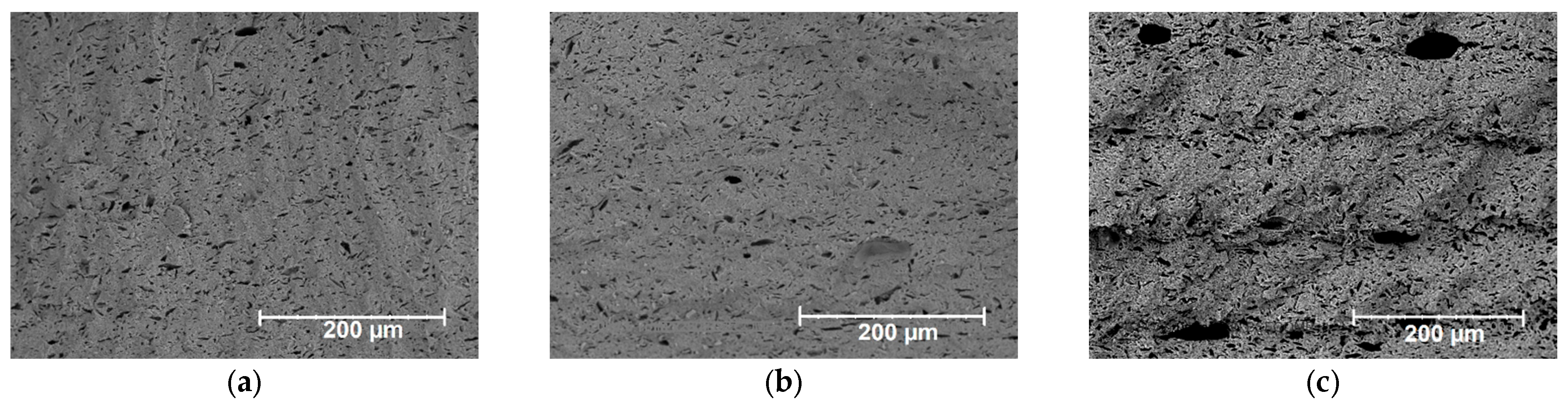
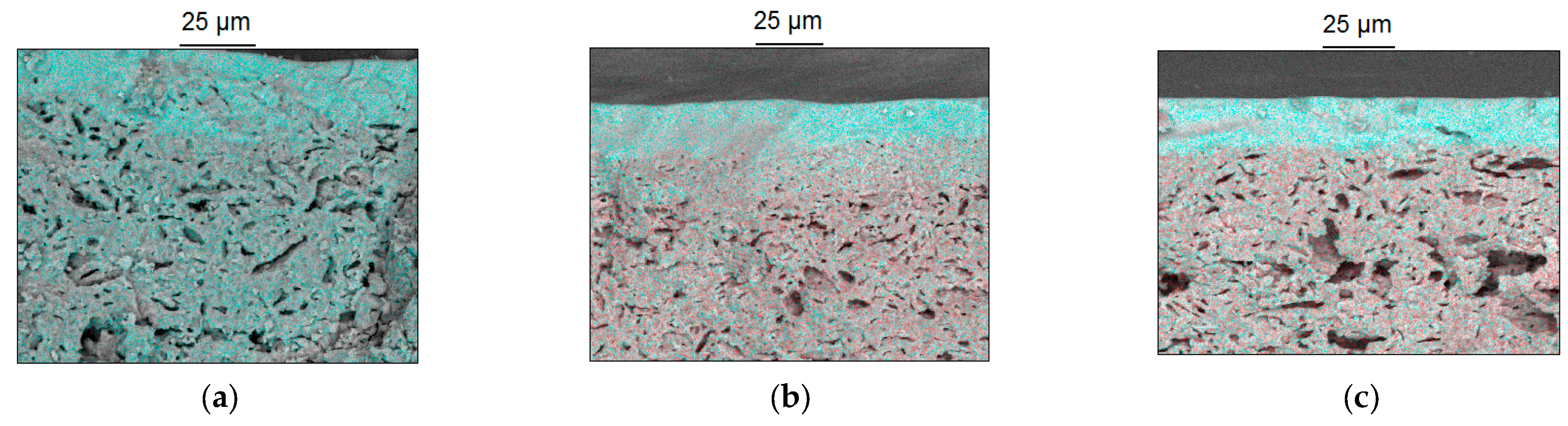
3. Results and Discussions

Figure 2a shows the particle size distribution of the NiO/10YSZ (60:40) composite used for 3D printing of the supporting anodes after milling and homogenization. When measuring the particle size, five cycles were done; therefore, the values plotted in Figure 2a are the average values calculated from five measurements. According to study [38], for the 3D printing of high-viscosity ceramic pastes, the optimum particle size should be ≤3 μm. Thus, the milling of the NiO/10YSZ (60:40) composite is a necessary technological stage when 3D printing the anode supports. Analysis of the percentile values D75 showed (Figure 2b) that the optimum milling and homogenization time of the NiO/10YSZ composite (60:40) is 1 h. A further increase in the milling time almost does not affect the average particle size.
In our earlier study [35], it was shown that the introduction of a pore former is required to achieve the optimum porosity of the anode support. Figure 3 shows the dependence of the dynamic viscosity on the shear rate for an organic binder and for pastes in the absence and the presence of the pore-former graphite (20 wt.%). In the case of the organic binder and the presence of the pore former, the dynamic viscosity of the paste remains unchanged, or it changes a little with increasing the shear rate; therefore, it shows Newtonian flow behavior. A similar flow behavior is typical for unfilled or weakly filled printing compositions [39]. In the case of a printing composition with graphite as the pore former, the dynamic viscosity of the paste decreases with increasing the shear rate, showing non-Newtonian or thixotropic flow behavior. The phenomenon of thixotropy for highly filled printing compositions, such as the paste based on the NiO/10YSZ composite and graphite, is due to the fact that the dispersed filler particles form aggregates under a static state, while under applied shear stress, the aggregates disintegrate, which leads to a decrease in viscosity.
In order to measure the thixotropic properties of the printing compositions, the thixotropy indexes were determined. The thixotropy index is the ratio between the viscosity of a sample at low and high shear rates [39] (in this study, shear rates were 2 and 20 s − 1). The results of the calculations are shown in Table 1. As seen, both the organic binder and the pastes in the absence and in the presence of the pore former show Newtonian flow behavior (1 < IT < 2). These data are of high practical value for the 3D printing process since the dynamics of the flow of printing composition significantly affect the quality of the printed sample [40]. Non-Newtonian fluids liquefy under pressure; therefore, the intrinsic viscosity of a droplet inside a nozzle can differ significantly from that of the ejected droplet. If the applied pressure is too high, the droplets will be torn apart, thus leading to a discontinuous stream of liquid from the nozzle [41]. In this regard, it can be concluded that the as-prepared printing composition meets the rheological requirements for hybrid 3D inkjet printing of an anode support.
Based on the printing tests carried out at different frequencies and print head valve opening times, the optimum mode for hybrid inkjet printing of NiO/10YSZ (60:40 wt%) anode supports in the presence of the pore former was selected. The optimized printing conditions are shown in Table 2.
The effect of laser exposure on the morphology of the anode supports printed with laser treatment at various laser exposures and sintered at 1350 °C was studied (Figure 4). The conventional inkjet printing procedure leads to the formation of a dense sample, which, however, has a porous structure due to the presence of the pore former in the printing composition. Nevertheless, the use of layer-by-layer laser treatment results in the formation of a unique morphology of the anode support with two types of porosity: longitudinal, interlayer porosity, and intralayer porosity formed in the presence of graphite. At a laser exposure of 18.1 J/cm2, a pronounced layered structure maintaining the intralayer porosity is formed. However, at a laser exposure of 51.0 J/cm2, the layered structure is destroyed with the formation of dense areas passing into large cavities 250–300 μm long. We suggest that the change in morphology is due to the partial removal of the organic binder from the sample during laser treatment. As a result, the area of laser exposure has a significantly higher porosity, and the higher the laser exposure, the wider the interlayer space. However, if the interlayer space is too wide and porous, it has a significantly lower hardness, thus leading to the collapse of the layers upon heating and their sintering into a dense non-layered structure. For this reason, a laser exposure of 36.7 J/cm2 was considered optimal for producing NiO/10YSZ anode support (60:40 wt%) with the optimized porous structure. The values of the anode support porosity are shown in Table 3. As seen, an increase in the laser exposure values results in an increase in the porosity. The porosity of the NiO/10YSZ (60:40 wt%) anode printed at a laser exposure of 51.0 J/cm2 is almost comparable to that obtained without laser post-treatment. Therefore, the anode supports printed at a laser exposure of 10.6 J/cm2 were selected to deposit further the electrolyte layer.
Figure 5a shows the granulometric composition of the 10YSZ powder used for the 3D printing of electrolytes after milling and homogenization. The values plotted in Figure 5a are the average values calculated from five measurements. Importantly, the particle size distribution of 10YSZ is a key factor in the formation of a thin, gas-tight electrolyte. Thus, electrolyte densification occurs much better when using particles with a small diameter; in addition, the microstructure after sintering submicron and nanosized particles has a much larger grain boundary and, thus, higher conductivity and lower activation energy [42]. In order to establish the optimal grinding time for the 10YSZ powder, percentile values of D75 were analyzed depending on the grinding time (Figure 5b). The optimized milling time for the 10YSZ powder was found to be 1 h (Figure 5b).
According to the data reported in the literature, a solid phase content in the pastes for the fabrication of a thin electrolyte for SOFC anode supports, depending on the type of organic binder and the volume fraction of the rest components, can vary from 5 to 50 wt% [43,44]. Too high a content of the solid phase in the paste can lead to delamination of the organic binder and solid phase and to the formation of too thick electrolyte layers, thus resulting in an increase in Ohmic resistance of the SOFC electrolyte layer [45]. At the same time, the low content of the solid phase in the paste composition leads to the need for multiple coating over a patterned anode substrate in order to obtain a layer of sufficient thickness. In this work, for the fabrication of the 10YSZ electrolyte, three pastes containing 15, 25, and 35 wt% 10YSZ were used. The dependence of the dynamic viscosity on the shear rate for electrolyte printing compositions with a different mass content of zirconium oxide is shown in Figure 6. As seen, all the printing compositions show nearly Newtonian flow behavior; therefore, they can be used to fabricate 10YSZ electrolyte structure by inkjet printing.
A series of experiments with different numbers of deposited electrolyte layers and different 10YSZ mass contents was carried out. It should be noted that in the case of 3D printing of a thin-layer electrolyte, laser post-treatment was not used in order to avoid the formation of porous and the distortion of the geometry of the electrolyte layer. Figure 7 shows SEM micrographs of the electrolyte surface obtained by inkjet 3D printing for the different mass contents of 10YSZ and the number of layers. As seen, in the case of 15% 10YSZ, the anode support surface was completely covered only when five electrolyte layers were deposited. When one and three layers of the electrolyte paste were deposited, the grooves, specific to hybrid printing, were formed. When five layers were deposited, the anode support grooves overlapped, but the 10YSZ electrolyte layer remained unevenly interspersed with pores. A similar trend is observed with 25% 10YSZ; however, the degree of coverage of the anode, in this case, is obviously higher. When the content of 10YSZ is 35%, the surface microstructure of the electrolyte is very different from the previous two (Figure 7e,f). As seen, the first layer deposited on the surface of the NiO-10YSZ anode support covers it fully with the formation of a gas-tight smooth coating.
The thickness of the electrolyte layers having a continuous structure was estimated using the SEM method (Table 4). Table 4 shows that the as-prepared printing compositions allow the fabrication of a dense electrolyte with a thickness that meets the requirements for a second generation of SOFC anode supports [46]. In Figure 8, the SEM cross-section images of the NiO-10YSZ/10YSZ half-cells with the electrolyte fabricated from the 35% 10YSZ paste with the different number of electrolyte layers are shown. As seen, a gas-tight electrolyte layer is formed after the first deposition of the printing composition on the anode support, thus allowing the fabrication of both porous thick anode supports and gas-tight thin-film electrolytes by hybrid inkjet printing.
Table 4. Effect of the 10YSZ mass content in the paste and the number of printing cycles on the average electrolyte thickness.
Number of Layers10YSZ Content in the Paste, wt%
152535
Electrolyte Thickness, μm
1Not formedNot formed11.7
3Not formed11.616.0
58.214.123.7
Apart from the anode support and electrolyte, the most important part of the SOFC half-cell is the anode functional layer disposed between the anode support and the electrolyte, which is commonly made of Ni/YSZ cermet with a high mass content of YSZ. A big difference between the porosity of the anode support and the electrolyte results in the formation of pores at the anode/electrolyte interface, which reduces the contact between the electrolyte and the porous substrate, thus reducing the length of the three-phase interface [47]. A decrease in the three-phase interface leads to a decrease in the efficiency of the corresponding anodic and cathodic reactions, which significantly impairs the fuel cell performance [48]. Figure 9 shows the effect of the shear rate on the dynamic viscosity of the paste for 3D printing of the NiO-10YSZ (40:60 wt%) anode functional layer. As seen, this printing composition shows Newtonian flow behavior; therefore, it can be used for inkjet printing.
The effect of laser post-treatment on the morphology of the AFL fabricated by hybrid 3D printing was studied. Figure 10 shows the SEM cross-section images and energy-dispersive X-ray spectroscopy (EDS) elemental mapping of the NiO-10YSZ/YSZ half-cells printed under different conditions. As seen, in the absence of the AFL, the macropores are observed at the electrolyte/anode interface, which reduce the three-phase interface and make worse the electrochemical SOFC performance. Laser post-treatment during the fabrication of the anode functional layer was shown to result in its complete destruction. In the absence of laser post-treatment, the anode functional layer does not contain macropores, and that improves the interfacial contact between the anode and electrolyte.

4. Conclusions

In this work, a new approach using hybrid 3D inkjet printing with laser and thermal post-treatment to prepare NiO-10YSZ/10YSZ half-cells for anode-supported solid oxide fuel cells has been developed. It was shown that the optimum porosity and morphology of the anode support are achieved at a laser exposure of 36.7 J/cm2. By using a printing composition containing 35 wt% 10YSZ, a gas-tight electrolyte layer was fabricated by depositing a single layer on an anode support. In this case, the minimum electrolyte thickness is 11.7 μm. It was shown that laser post-treatment leads to the complete destruction of the anode functional layer, while, without laser post-treatment, a gradient porosity of the half-cell with an increased three-phase boundary can be achieved. Hybrid 3D inkjet printing is a unique method that can be used to fabricate both porous anode supports and gas-tight thin-film 10YSZ electrolytes. This approach opens up great opportunities for the application of hybrid 3D inkjet printing to produce anode-supported SOFC half-cells. The comprehensive technology that makes it possible to produce equally well both porous supporting anode layers and thin gas-tight electrolyte coatings will significantly simplify and reduce the cost of the production of SOFC half-cells, through both saving the working areas and significantly lower consumption of expensive oxide materials. In addition, a high degree of automation of the inkjet printing and laser post-treatment processes will help to reproduce the complex microstructure of solid oxide fuel cells with a high degree of accuracy. It is important to note that further development of this work will be aimed at minimizing the stages of thermal sintering by increasing the laser output power, which, in turn, will significantly reduce the manufacturing time of SOFC half-cells.

Author Contributions

Conceptualization, A.T.; investigation, I.M., A.B., A.V., E.L. and T.B.; data curation, I.M., E.L. and A.T.; writing—original draft, I.M.; writing—review and editing, O.L. and A.T.; visualization, I.M. and A.V.; supervision, A.T.; project administration, A.T. All authors have read and agreed to the published version of the manuscript.

Funding

This research was funded by the Russian Scientific Foundation, grant number 21-79-30051.

Data Availability Statement

Not applicable.

Conflicts of Interest

The authors declare no conflict of interest. The funders had no role in the design of the study; in the collection, analyses, or interpretation of data; in the writing of the manuscript; or in the decision to publish the results.

References

  1. Filippov, S.P.; Yaroslavtsev, A.B. Hydrogen energy: Development prospects and materials. Russ. Chem. Rev. 2021, 90, 627–643. [Google Scholar] [CrossRef]
  2. Nicoletti, G.; Arcuri, N.; Nicoletti, G.; Bruno, R. A technical and environmental comparison between hydrogen and some fossil fuels. Energy Convers. Manag. 2015, 89, 205–213. [Google Scholar] [CrossRef]
  3. Chaubey, R.; Sahu, S.; James, O.O.; Maity, S. A review on development of industrial processes and emerging techniques for production of hydrogen from renewable and sustainable sources. Renew. Sustain. Energy Rev. 2013, 23, 443–462. [Google Scholar] [CrossRef]
  4. Golkhatmi, S.Z.; Asghar, M.I.; Lund, P.D. A review on solid oxide fuel cell durability: Latest progress, mechanisms, and study tools. Renew. Sustain. Energy Rev. 2022, 161, 112339. [Google Scholar] [CrossRef]
  5. Stambouli, A.B.; Traversa, E. Solid oxide fuel cells (SOFCs): A review of an environmentally clean and efficient source of energy. Renew. Sustain. Energy Rev. 2002, 6, 433–455. [Google Scholar] [CrossRef]
  6. Xu, Q.; Guo, Z.; Xia, L.; He, Q.; Li, Z.; Bello, I.T.; Zheng, K.; Ni, M. A comprehensive review of solid oxide fuel cells operating on various promising alternative fuels. Energy Convers. Manag. 2022, 253, 115175. [Google Scholar] [CrossRef]
  7. Singh, M.; Zappa, D.; Comini, E. Solid oxide fuel cell: Decade of progress, future perspectives and challenges. Int. J. Hydrogen Energy 2021, 46, 27643–27674. [Google Scholar] [CrossRef]
  8. Baharuddin, N.A.; Muchtar, A.; Sulong, A.B.; Abdullah, H. Fabrication methods for planar solid oxide fuel cells: A review. Adv. Mat. Res. 2013, 662, 396–401. [Google Scholar] [CrossRef]
  9. Jang, I.; Kelsall, G.H. Fabrication of 3D NiO-YSZ structures for enhanced performance of solid oxide fuel cells and electrolysers. Electrochem. Commun. 2022, 137, 107260. [Google Scholar] [CrossRef]
  10. Zhang, Y.; Huang, X.; Lu, Z.; Liu, Z.; Ge, X.; Xu, J.; Xin, X.; Sha, X.; Su, W. A study of the process parameters for yttria-stabilized zirconia electrolyte films prepared by screen-printing. J. Power Sources 2006, 160, 1065–1073. [Google Scholar] [CrossRef]
  11. Zhu, X.; Lü, Z.; Wei, B.; Huang, X.; Zhang, Y.; Su, W. A symmetrical solid oxide fuel cell prepared by dry-pressing and impregnating methods. J. Power Sources 2011, 196, 729–733. [Google Scholar] [CrossRef]
  12. Meng, G.; Song, H.; Xia, C.; Liu, X.; Peng, D. Novel CVD techniques for Micro-and IT-SOFC fabrication. Fuel Cells 2004, 4, 48–55. [Google Scholar] [CrossRef]
  13. Pederson, L.R.; Singh, P.; Zhou, X.D. Application of vacuum deposition methods to solid oxide fuel cells. Vacuum 2006, 80, 1066–1083. [Google Scholar] [CrossRef]
  14. Minary-Jolandan, M. Formidable Challenges in Additive Manufacturing of Solid Oxide Electrolyzers (SOECs) and Solid Oxide Fuel Cells (SOFCs) for Electrolytic Hydrogen Economy toward Global Decarbonization. Ceramics 2022, 5, 761–779. [Google Scholar] [CrossRef]
  15. Lomberg, M.; Boldrin, P.; Tariq, F.; Offer, G.; Wu, B.; Brandon, N.P. Additive manufacturing for solid oxide cell electrode fabrication. ECS Trans. 2015, 68, 2119–2127. [Google Scholar] [CrossRef] [Green Version]
  16. Sun, C.; Wang, Y.; McMurtrey, M.D.; Jerred, N.D.; Liou, F.; Li, J. Additive manufacturing for energy: A review. Appl. Energy 2021, 282, 116041. [Google Scholar] [CrossRef]
  17. Rasaki, S.A.; Liu, C.; Lao, C.; Zhang, H.; Chen, Z. The innovative contribution of additive manufacturing towards revolutionizing fuel cell fabrication for clean energy generation: A comprehensive review. Renew. Sustain. Energy Rev. 2021, 148, 111369. [Google Scholar] [CrossRef]
  18. Sobolev, A.; Stein, P.; Borodianskiy, K. Synthesis and characterization of NiO colloidal ink solution for printing components of solid oxide fuel cells anodes. Ceram. Int. 2020, 46, 25260–25265. [Google Scholar] [CrossRef]
  19. Rahumi, O.; Sobolev, A.; Rath, M.K.; Borodianskiy, K. Nanostructured engineering of nickel cermet anode for solid oxide fuel cell using inkjet printing. J. Eur. Ceram. Soc. 2021, 41, 4528–4536. [Google Scholar] [CrossRef]
  20. Tomov, R.I.; Fakeeh, A.; Krishnan, V.V.; Balasubramanian, K.; Kumar, V.R.; Glowacki, B.A. Direct ceramic inkjet printing and infiltration of functional coatings for metal supported SOFC. ECS Trans. 2015, 68, 2491–2497. [Google Scholar] [CrossRef]
  21. Pham, T.T.; Tu, H.P.; Dao, T.D.; To, T.D.; Doan, D.C.T.; Dang, M.C. Fabrication of an anode functional layer for an electrolyte-supported solid oxide fuel cell using electrohydrodynamic jet printing. Adv. Nat. Sci. Nanosci. Nanotechnol. 2019, 10, 015004. [Google Scholar] [CrossRef]
  22. Derby, B. Inkjet printing ceramics: From drops to solid. J. Eur. Ceram. Soc. 2011, 31, 2543–2550. [Google Scholar] [CrossRef]
  23. Seo, H.; Iwai, H.; Kishimoto, M.; Ding, C.; Saito, M.; Yoshida, H. Microextrusion printing for increasing electrode–electrolyte interface in anode-supported solid oxide fuel cells. J. Power Sources 2020, 450, 227682. [Google Scholar] [CrossRef]
  24. Seo, H.; Kishimoto, M.; Ding, C.; Iwai, H.; Saito, M.; Yoshida, H. Improvement in the Electrochemical Performance of Anode-supported Solid Oxide Fuel Cells by Meso-and Nanoscale Structural Modifications. Fuel Cells 2020, 20, 570–579. [Google Scholar] [CrossRef]
  25. Simonenko, T.L.; Simonenko, N.P.; Gorobtsov, P.Y.; Simonenko, E.P.; Kuznetsov, N.T. Microextrusion Printing of Multilayer Hierarchically Organized Planar Nanostructures Based on NiO, (CeO2)0.8(Sm2O3)0.2 and La0.6Sr0.4Co0.2Fe0.8O3−δ. Micromachines 2022, 14, 3. [Google Scholar] [CrossRef] [PubMed]
  26. Komissarenko, D.A.; Sokolov, P.S.; Evstigneeva, A.D.; Slyusar, I.V.; Nartov, A.S.; Volkov, P.A.; Lyskov, N.V.; Evdokimov, P.V.; Putlayev, V.I.; Dosovitsky, A.E. DLP 3D printing of scandia-stabilized zirconia ceramics. J. Eur. Ceram. Soc. 2021, 41, 684–690. [Google Scholar] [CrossRef]
  27. Jia, K.; Zheng, L.; Liu, W.; Zhang, J.; Yu, F.; Meng, X.; Li, C.; Sunarso, J.; Yang, N. A new and simple way to prepare monolithic solid oxide fuel cell stack by stereolithography 3D printing technology using 8 mol% yttria stabilized zirconia photocurable slurry. J. Eur. Ceram. Soc. 2022, 42, 4275–4285. [Google Scholar] [CrossRef]
  28. Wei, L.; Zhang, J.; Yu, F.; Zhang, W.; Meng, X.; Yang, N.; Liu, S. A novel fabrication of yttria-stabilized-zirconia dense electrolyte for solid oxide fuel cells by 3D printing technique. Int. J. Hydrogen Energy 2019, 44, 6182–6191. [Google Scholar] [CrossRef]
  29. Li, W.; Ghazanfari, A.; McMillen, D.; Leu, M.C.; Hilmas, G.E.; Watts, J. Characterization of zirconia specimens fabricated by ceramic on-demand extrusion. Ceram. Int. 2018, 44, 12245–12252. [Google Scholar] [CrossRef]
  30. Ghazanfari, A.; Li, W.; Leu, M.C.; Watts, J.L.; Hilmas, G.E. Additive manufacturing and mechanical characterization of high density fully stabilized zirconia. Ceram. Int. 2017, 43, 6082–6088. [Google Scholar] [CrossRef] [Green Version]
  31. Varghese, G.; Moral, M.; Castro-García, M.; López-López, J.J.; Marín-Rueda, J.R.; Yagüe-Alcaraz, V.; Hernández-Afonso, L.; Ruiz-Morales, J.C.; Canales-Vázquez, J. Fabrication and characterisation of ceramics via low-cost DLP 3D printing. Bol. Soc. Esp. Ceram. Vidr. 2018, 57, 9–18. [Google Scholar] [CrossRef]
  32. Esposito, V.; Gadea, C.; Hjelm, J.; Marani, D.; Hu, Q.; Agersted, K.; Ramousse, S.; Jensen, S.H. Fabrication of thin yttria-stabilized-zirconia dense electrolyte layers by inkjet printing for high performing solid oxide fuel cells. J. Power Sources 2015, 273, 89–95. [Google Scholar] [CrossRef]
  33. Ahmed, M.; Jones, T.D.A.; Abdolvand, A. Ink formulation and printing of electrolyte for a doped ceria solid oxide fuel cell. Mater. Lett. 2022, 327, 132999. [Google Scholar] [CrossRef]
  34. Merino, R.I.; Laguna-Bercero, M.A.; Lahoz, R.; Larrea, Á.; Oliete, P.B.; Orera, A.; Pena, J.I.; Sanjuán, M.L.; Sola, D. Laser processing of ceramic materials for electrochemical and high temperature energy applications. Bol. Soc. Esp. Ceram. Vidr. 2022, 61, 19–39. [Google Scholar] [CrossRef]
  35. Malbakhova, I.; Bagishev, A.; Vorobyev, A.; Borisenko, T.; Logutenko, O.; Titkov, A. Fabrication of NiO/YSZ-Based Anodes for Solid Oxide Fuel Cells by Hybrid 3D Inkjet Printing and Laser Treatment. Ceramics 2022, 5, 1115–1127. [Google Scholar] [CrossRef]
  36. Bagishev, A.S.; Mal’bakhova, I.M.; Vorob’ev, A.M.; Borisenko, T.A.; Asmed’yanova, A.D.; Titkov, A.I.; Nemudryi, A.P. Layer-by-Layer Formation of the NiO/CGO Composite Anode for SOFC by 3D Inkjet Printing Combined with Laser Treatment. Russ. J. Electrochem. 2022, 58, 600–605. [Google Scholar] [CrossRef]
  37. Ye, G.; Ju, F.; Lin, C.; Gopalan, S.; Pal, U.; Seccombe, D.A. Low-cost single-step co-firing technique for SOFC manufacturing. ECS Proc. Vol. 2005, 2005, 451–458. [Google Scholar] [CrossRef]
  38. Gunduz, I.E.; McClain, M.S.; Cattani, P.; Chiu, G.T.-C.; Rhoads, J.F.; Son, S.F. 3D printing of extremely viscous materials using ultrasonic vibrations. Addit. Manuf. 2018, 22, 98–103. [Google Scholar] [CrossRef]
  39. Licari, J.J.; Swanson, D.W. Adhesives Technology for Electronic Applications: Materials, Processing, Reliability; William Andrew: Norwich, NY, USA, 2011. [Google Scholar]
  40. Bazilevskii, A.V.; Meyer, J.D.; Rozhkov, A.N. Dynamics and breakup of pulse microjets of polymeric liquids. Fluid Dyn. 2005, 40, 376–392. [Google Scholar] [CrossRef]
  41. Hutchings, I.M.; Martin, G.D.; Hoath, S.D. High speed imaging and analysis of jet and drop formation. J. Imaging Sci. Technol. 2007, 51, 438–444. [Google Scholar] [CrossRef]
  42. Zhang, J.; Huang, X.; Zhang, H.; Xue, Q.; Xu, H.; Wang, L.; Feng, Z. The effect of powder grain size on the microstructure and electrical properties of 8 mol% Y2O3-stabilized ZrO2. RSC Adv. 2017, 7, 39153–39159. [Google Scholar] [CrossRef] [Green Version]
  43. Lenormand, P.; Caravaca, D.; Laberty-Robert, C.; Ansart, F. Thick films of YSZ electrolytes by dip-coating process. J. Eur. Ceram. Soc. 2005, 25, 2643–2646. [Google Scholar] [CrossRef] [Green Version]
  44. Cebollero, J.A.; Laguna-Bercero, M.A.; Lahoz, R.; Silva, J.; Moreno, R.; Larrea, A. Optimization of laser-patterned YSZ-LSM composite cathode-electrolyte interfaces for solid oxide fuel cells. J. Eur. Ceram. Soc. 2019, 39, 3466–3474. [Google Scholar] [CrossRef] [Green Version]
  45. Ishiyama, T.; Kishimoto, H.; Yamaji, K.; Horita, T.; Yokokawa, H. Calculation of ohmic resistance increase induced by phase transformation of zirconia electrolyte in SOFC cell by Raman spectroscopy. ECS Trans. 2019, 91, 809–813. [Google Scholar] [CrossRef]
  46. Dunyushkina, L. Solid oxide fuel cells with a thin film electrolyte: A review on manufacturing technologies and electrochemical characteristics. J. Electrochem. Sci. Technol. 2022, 1, 1–25. [Google Scholar] [CrossRef]
  47. Yoon, D.; Lee, J.J.; Park, H.G.; Hyun, S.H. NiO/YSZ–YSZ nanocomposite functional layer for high performance solid oxide fuel cell anodes. J. Electrochem. Soc. 2010, 157, B455. [Google Scholar] [CrossRef]
  48. Bi, L.; Fabbri, E.; Traversa, E. Effect of anode functional layer on the performance of proton-conducting solid oxide fuel cells (SOFCs). Electrochem. Commun. 2012, 16, 37–40. [Google Scholar] [CrossRef]
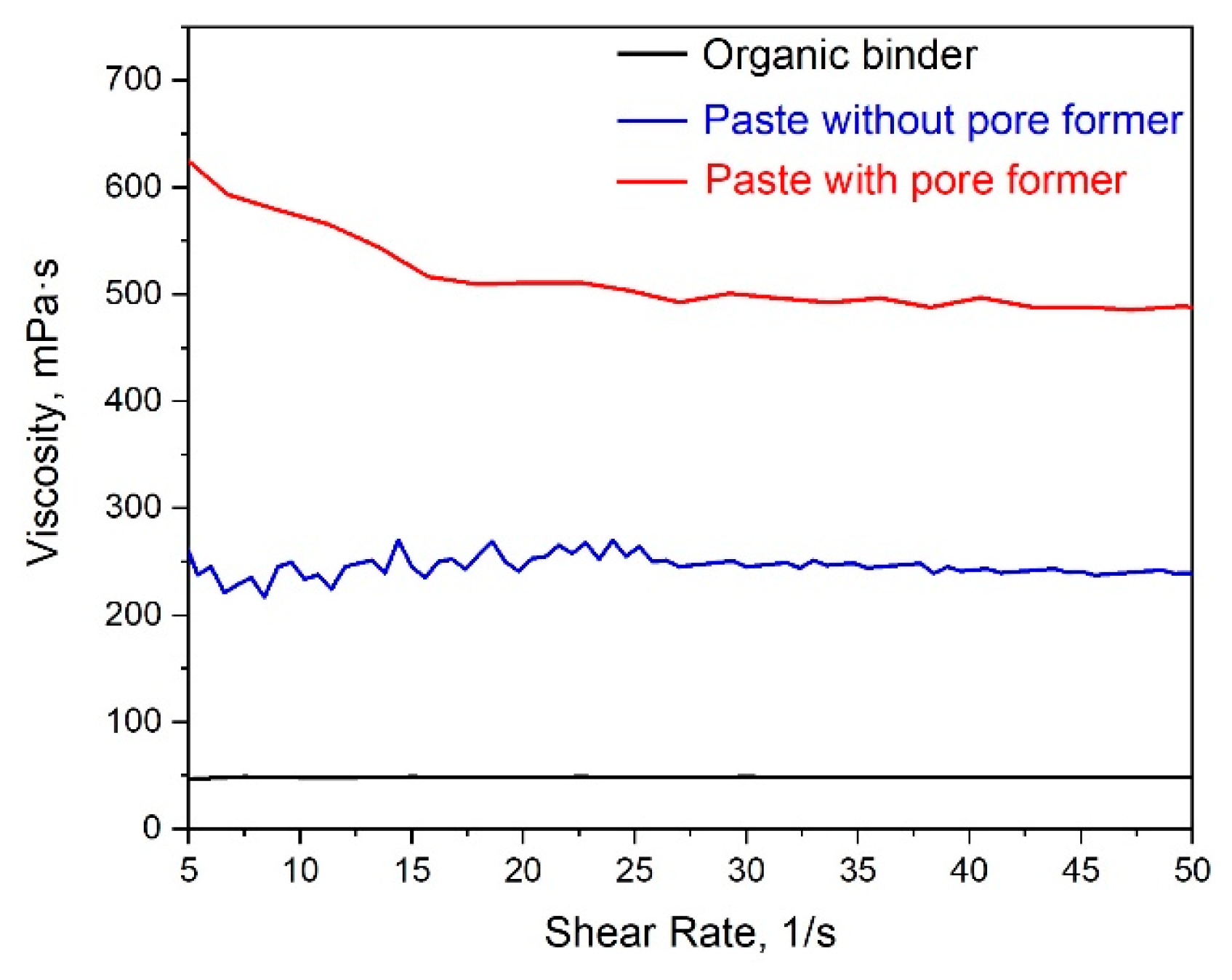
Figure 1. (a) A general view of the printing unit of a hybrid 3D inkjet printer. (b) Photographs of the NiO/YSZ anode sintered at 1100 °C, electrolyte-coated YSZ anode, and NiO-YSZ/YSZ half-cell sintered at 1350 °C.
Ceramics 06 00085 g001
Figure 2. (a) Particle size distribution of the NiO/10YSZ (60:40) composite after milling and homogenization. (b) Effect of milling time on the percentile value D75 for the particle size distribution of the NiO/10YSZ (60:40) composite.
Ceramics 06 00085 g002
Figure 3. Dynamic viscosity as a function of shear rate for pastes for the formation of SOFC anode support.
Ceramics 06 00085 g003
Figure 4. SEM images of cross sections of the NiO/10YSZ anode supports sintered at 1350 °C at various laser exposure values: (a) without laser treatment; (b) 3.1 J/cm2; (c) 18.1 J/cm2; (d) 25.6 J/cm2; (e) 36.7 J/cm2; (f) 51.0 J/cm2.
Ceramics 06 00085 g004aCeramics 06 00085 g004b
Figure 5. (a) Particle size distribution of 10YSZ after milling. (b) Effect of milling time on the percentile value D75 for the particle size distribution of 10YSZ.
Ceramics 06 00085 g005
Figure 6. Dynamic viscosity of the printing pastes as a function of shear rate for the formation of SOFC electrolyte.
Ceramics 06 00085 g006
Figure 7. SEM micrographs of the surface of the electrolyte fabricated using the pastes with the different mass content of 10YSZ and the number of layers: (a) 15% 10YSZ, one layer; (b) 25% 10YSZ, one layer; (c) 35% 10YSZ, one layer; (d) 15% 10YSZ, five layers; (e) 25% 10YSZ, five layers; (f) 35% 10YSZ, five layers.
Ceramics 06 00085 g007
Figure 8. SEM cross-section images of the NiO-10YSZ/YSZ half-cells with the different number of electrolyte layers made from the 35% 10YSZ paste: (a) one layer; (b) five layers.
Ceramics 06 00085 g008
Figure 9. Dynamic viscosity as a function of shear rate for pastes for the fabrication of the SOFC anode functional layers.
Ceramics 06 00085 g009
Figure 10. SEM cross-section images and energy-dispersive X-ray spectroscopy (EDS) data of the NiO-10YSZ/10YSZ half-cells printed with different anode functional layers (blue–Zr, red–Ni): (a) without AFL; (b) with AFL but without laser post-treatment; (c) with both AFL and laser post-treatment at a laser exposure of 25.6 J/cm2.
Ceramics 06 00085 g010
Table 1. The values of the thixotropy indexes of pastes for SOFC anode supports.
Paste CompositionThixotropy Index (TI)
Organic binder1.01
Paste without pore former1.06
Paste with pore former1.24
Table 2. Optimum hybrid inkjet printing conditions for fabrication of NiO/YSZ anode supports (60:40 wt.%).
ParameterValue
Nozzle diameter250 μm
Nozzle inlet pressure 2.1 atm
Nozzle raster0.4 mm
Laser raster0.091 mm
Table 3. The values of porosity for the NiO/YSZ anode support sintered at different laser exposures.
Exposure Values, J/cm2Porosity, %
012.6
3.114.1
18.119.8
25.622.5
36.729.9
51.033.4 (taking into account the large cavities)
12.9 (not taking into account the large cavities)
Disclaimer/Publisher’s Note: The statements, opinions and data contained in all publications are solely those of the individual author(s) and contributor(s) and not of MDPI and/or the editor(s). MDPI and/or the editor(s) disclaim responsibility for any injury to people or property resulting from any ideas, methods, instructions or products referred to in the content.

