Article

Polymer-Infiltrated Ceramic Network Produced by Direct Ink Writing: The Effects of Manufacturing Design on Mechanical Properties

1
CIEFMA-Departament de Ciència i Enginyeria de Materials, Campus Diagonal Besòs (EEBE), Universitat Politècnica de Catalunya-Barcelona Tech, c/Eduard Maristany, 10-14, Building I, 1st Floor, 08019 Barcelona, Spain
2
Barcelona Research Center for Multiscale Science and Engineering, Campus Diagonal Besòs (EEBE), Universitat Politècnica de Catalunya-Barcelona Tech, c/Eduard Maristany, 10-14, Building I, Basement Floor, 08019 Barcelona, Spain
3
IMEM-Departament d’Enginyeria Química, Campus Diagonal Besòs (EEBE), Universitat Politècnica de Catalunya-Barcelona Tech, c/Eduard Maristany, 10-14, Building I, 2nd Floor, 08019 Barcelona, Spain
4
PROCOMAME-Departament de Ciència i Enginyeria de Materials, Universitat Politècnica de Catalunya-BarcelonaTech, c/Eduard Maristany, 10-14, Building I, 1st Floor, 08019 Barcelona, Spain
5
Fundació CIM UPC, c/Llorens i Artigas, 12, 08021 Barcelona, Spain
*
Authors to whom correspondence should be addressed.
Ceramics 2024, 7(2), 436-451; https://doi.org/10.3390/ceramics7020028
Submission received: 23 February 2024 / Revised: 17 March 2024 / Accepted: 18 March 2024 / Published: 22 March 2024
(This article belongs to the Special Issue Advances in Ceramics, 2nd Edition)

Abstract

:
Polymer-infiltrated ceramic network (PICN) materials have gained considerable attention as tooth-restorative materials due to their mechanical compatibility with human teeth, especially with computer-aided design and computer-aided manufacturing (CAD/CAM) technologies. However, the designed geometry affects the mechanical properties of PICN materials. This study aims to study the relationship between manufacturing geometry and mechanical properties. In doing so, zirconia-based PICN materials with different geometries were fabricated using a direct ink-writing process, followed by copolymer infiltration. Comprehensive analyses of the microstructure and structural properties of zirconia scaffolds, as well as PICN materials, were performed. The mechanical properties were assessed through compression testing and digital image correlation analysis. The results revealed that the compression strength of PICN pieces was significantly higher than the respective zirconia scaffolds without polymer infiltration. In addition, two geometries (C-grid 0 and C-grid 45) have the highest mechanical performance.

Graphical Abstract

1. Introduction

Additive manufacturing (AM), or 3D printing, is the process of joining materials to fabricate objects from 3D model data, usually layer by layer, which is distinct from machining, casting, and forming [1]. It is a well-established and suitable technology for constructing restorative materials, particularly following the significant advances in computer-aided design and computer-aided manufacturing (CAD/CAM) technologies [2]. AM allows dental pieces to have shape complexity while reducing waste material and capital costs for fabrication. To date, there are several AM techniques, such as fused deposition modeling [3], stereolithography [4,5], binder jetting [6,7], selective laser sintering [8,9], and direct ink writing (DIW) [10,11]. Among these, the DIW technique, an extrusion-based AM method, is a simple, adaptable, and economical approach appropriate for patterning and depositing various materials. This approach has been widely used to develop dental prostheses, dental models, and temporary crowns [12,13].
At present, 3D-printable ceramic restorations have been implemented in dentistry due to their excellent biocompatibility, aesthetics, and mechanical properties [2]. Zirconia, especially doped with 3 mol.% yttria, has emerged as the primary material for 3D-printable ceramics in the application of prosthetic fields, including crowns, bridges, endodontic posts and cores, abutments, and dental implants [14,15]. However, there are still clear limitations of the material that prevent its use as a one-piece biomedical prosthesis, such as its high brittleness and hardness, which is incompatible with enamel and dentin [16].
Aiming to overcome this drawback and design restorations with an actual tooth-like function, polymer-infiltrated ceramic network (PICN) materials have been recently developed [17]. PICNs have a dual-network structure comprising a ceramic skeleton and infiltrated resin phase, generally fabricated by infiltrating the polymerizable monomers into the pre-sintered ceramic skeleton and curing by heat-induced polymerization [2,18,19]. PICNs were expected to have a good combination of strength, ceramics esthetics, and polymers’ machinability.
Zirconia is considered a promising ceramic matrix for PICN material. The mechanical properties of zirconia-based PICNs, such as hardness and Young’s modulus, are similar to human enamel [20,21]. Zirconia-based PICNs have potential applications in tooth-restorative materials. Ikemoto et al. [21] fabricated zirconia-based PICN networks for dental restorative materials via slip casting. The results highlighted that a zirconia-based PICN displayed higher strength than commercial resin composites and PICN. Hodasova et al. [10,22] prepared 3D-printable PICNs by combining 3D-printed ZrO2 with 50% infilled macropores and biocompatible adhesive copolymer for dental implants. These PICNs possessed excellent compression strength with moderate hardness. On the other hand, it is found that the final performance of PICN materials is affected by the properties of a porous ceramic matrix, which is, in turn, is influenced by the geometry of the printed parts [23,24,25]. It means that altering the geometry can leverage specific properties of the matrix for better performance, which is crucial in tailoring PICNs for particular applications. To the best of our knowledge, there are no reports on the impacts of the manufacturing design of zirconia scaffolds on the mechanical properties of zirconia-based PICNs.
In this work, 3Y-ZrO2 powder was used to fabricate PICN scaffolds with different geometries infiltrated by a biocompatible polymer. The aim was to evaluate the effect of manufacturing design on the structural and mechanical properties of PICNs. Six different geometries have been designed. The resulting microstructures and mechanical properties have been investigated. PICNs’ behavior under compressive testing in conjunction with digital image correlation (DIC) analysis was detailed. They were linked to the nature and characteristics of defects within the samples. Accordingly, the influence of such defects on the mechanical properties was discussed in detail.

2. Materials and Methods

2.1. Materials

Zirconia powder stabilized with 3 mol% yttria (3Y-ZrO2) was purchased from Tosoh Corporation (TZ-3YSB-E, Tosoh, Japan). Table 1 shows the manufacturing values of 3Y-ZrO2 from Tosoh Inc. (Tokyo, Japan) [26]. Pluronic® F-127, 3-(trimethoxysilyl) propyl methacrylate (γ-MPS), bisphenol A glycerolate dimethacrylate (Bis-GMA), (triethylene glycol dimethacrylate) (TEGDMA), and benzoyl peroxide (BPO) were all supplied by Sigma-Aldrich (Madrid, Spain). All chemicals were used as received without further purification.

2.2. Preparation of Zirconia-Based PICN

Zirconia-based PICNs were fabricated via direct ink writing of zirconia scaffolds, followed by a polymer-infiltration process. The details of each step are as follows.

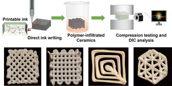
2.2.1. Preparation of Zirconia Scaffolds via Direct Ink Writing Method

The detailed procedure for scaffold preparation has been recently reported in our previous work [25]. Figure 1 presents the principle of printing zirconia scaffolds via DIW. First, Pluronic® F-127 hydrogel was prepared from 25 wt.% Pluronic® F-127 powder and 75 wt.% distilled water. Once the mixture was prepared, it was subsequently cooled down at 4 °C for 24 h to dissipate the defects as air bubbles induced during the mixing process. Afterward, 3Y-ZrO2 powder (73 wt.%) was mixed with hydrogel (27 wt.%) using a SpeedMixer (DAC a50.1 FVZ-k) at 3500 rpm for 5 min. The optimal ceramic content here was obtained elsewhere [27]. The prepared inks were then transferred into plastic syringes (10 cc) with a nozzle diameter of 840 μm (EFD, Nordson, OH, USA).
Zirconia scaffolds with the desired geometry (based on 3D digital models) were then continued to be printed using a DIW prototype (Fundació CIM-UPC, Barcelona, Spain). The printing process was performed at room temperature. The parameters selected to fabricate the samples, printing speed, and pressure were 2 mm/s and 4–6 Bar, respectively.
The printed samples were left in a closed box for 5 days with a relative humidity of 50%. Then, a two-step sintering process (700 °C for 1 h and 1450 °C for 2 h) was performed, and sintered zirconia scaffolds were obtained. Heating and cooling rates were held constant at 3 °C/min.
In the present work, six sets of samples were considered to evaluate microstructural and mechanical properties and be able to investigate geometry effects on microstructural features and mechanical properties. They were named based on geometry: cube (C), cylinder (CY), or hexagon (H), followed by its infill pattern, Figure 2. Samples with 100% infill were also produced to compare with the porosity ones. In this regard, samples with 100% infill and different printing geometries were prepared, named C-100%, CY-100%, and H-100%, respectively.

2.2.2. Preparation of the Polymer-Infiltrated Ceramic Networks

The preparation of PICNs was performed in two different steps, as reported in [22]. In the first one, the 3D-printed porous scaffolds were treated with γ-MPS solution (24 mmol of liquid silane in 100 mL of 3:1 ethanol–water volume ratio) for 1 h to active the zirconia surface with the silane coupling agent. In the second step, the silane-activated pieces were immersed in a viscous solution (39.5 wt.% of Bis-GMA, 59.5 wt.% of TEGDMA monomers, and 1 wt.% of BPO initiator) for 1 h, followed by the removal of the solution. The prepared hybrid system was placed in a vacuum oven in an aluminum foil-covered glass Petri dish to complete the curing process at 115 °C for 10 h, Figure 1.

2.3. Characterization

The 3Y-ZrO2 powder and grain size were characterized through field-emission scanning electron microscopy (FESEM, Carl Zeiss Neon 40, Oberkochen, Germany). The scanning was performed at 5 kV. Thermal etching was employed on the sintered samples at 1300 °C for 1 h to analyze the grain size. The linear intercept method was applied to ascertain the grain size number distribution.
Crystalline structures of the 3Y-ZrO2 powder and sintered samples were identified by X-ray diffraction (XRD, Bruker D8 Advance Diffractometer, Billerica, MA, USA), using Cu Kα radiation (40 kV and 40 mA) within the 2θ range from 10° to 90° with an angular step of 0.02° at 10 s per step. The monoclinic phase content ( V m ) was calculated using the equations provided in Ref. [28], while Debye–Scherrer’s formula was employed to determine the crystallite size [29].
Dimensions of sintered samples were measured using a digital caliper along three perpendicular axes. The x and y axes were parallel to the printing plane, and the z-axis was perpendicular to the printing direction. The shrinkage rate (S) in each direction was calculated according to:
S % = L 0 L 1 L 0 × 100 %
where L 0 and L 1 are the sizes of the original 3D model (from SolidWorks 2016) and the sintered samples, respectively.
Density was evaluated based on the Archimedes method in distilled water, whereas the density of zirconia powder was taken from the manufacturer’s specifications (6.05 g/cm3).
The scaffolds porosity ( P s c a f f o l d ) was determined through the division of the scaffolds’ weight ( m s c a f f o l d ) by the theoretical weight of a scaffold with 100% infill ( m t h e o r e t i c a l ), as follows [10]:
P s c a f f o l d = 1 m s c a f f o l d m t h e o r e t i c a l × 100 %
m t h e o r e t i c a l = ρ × V s c a f f o l d
where ρ is the density of material (6.05 g/cm3) and V s c a f f o l d is the volume of scaffold, obtained from the dimensions of the sample. Five measurements per sample were made to get statistical significance.
The pore distribution of zirconia 3D-printed scaffolds was assessed by optical microscopy using an Olympus BX53M (Shinjuku, Tokyo, Japan).
The structure and overall architecture of 3D-printed zirconia scaffolds were analyzed with an X-ray computed microtomography (micro-CT, SkyScan 1272, Bruker, Kontich, Belgium). The measurements were conducted at a source voltage of 100 keV and a current of 100 μA, with a pixel size of 4.6 μm. Three-dimensional (3D) reconstruction and image analysis were received from Nrecon (version 1.7.0.4) and CTAn software (1.16.9.0) from Bruker, respectively.
The polymer Infiltration (I) into the pores was derived from the following equation:
I = m P I C N m P I C N T × 100 = ( m P I C N ρ P I C N ( E ) × V P I C N ) × 100
where m P I C N is the weight of PICN composite, m P I C N ( T ) is the theoretical weight of PICN specimen with 100% pores infiltrated, ρ P I C N ( E ) is the density of PICN composite, and V P I C N is the volume of PICN, figured out from the dimension data. ρ P I C N ( E ) was estimated from Equation (5):
ρ P I C N ( E ) = 1 P s c a f f o l d 100 × ρ z i r c o n i a + ( P s c a f o l d 100 ) × ρ C o p o l y m e r
where ρ z i r c o n i a and ρ C o p o l y m e r are the density of zirconia (6.05 g/cm3) and copolymer (1.18 g/cm3), respectively.
Compression tests of printed scaffolds and PICNs were conducted using an Instron 8500 universal testing machine under a load rate of 20 N/s. The samples were compressed in the direction of layer-by-layer growth. A digital image correlation (DIC) system was utilized to record compression experiments and obtain the deformation information. As a non-contact measurement method, DIC examines the entire-field deformation over the side surface of the samples by capturing images with a digital camera during load conditions. It begins with an initial image before loading and subsequently captures additional ones during the object’s deformation. The deformed pictures display a different pattern dot than the first one. With computer software, these differences between patterns can be calculated by correlating all the pixels of the first image and the deformed images. Then, the surface displacement and strain field can be created [30,31,32]. This is an established approach [33,34] and has been incorporated for the analysis of various materials’ behavior (e.g., composites [35], aluminum foams [36], mild steels [37], and porous ceramics [38]). Before the test, samples were covered by white paint, followed by black speckles for image analysis. Failure behavior under compression pressure was recorded in real time by a camera (Basler acA2440-75 um) at a speed of 2 frames each second. Vic 2D software (version 6, Correlated Solutions Inc., Irmo, SC, USA) was used to acquire displacements and strains. The area of interest was divided into 25 × 25 pixel subsets, with each subset having a step size of 7 pixels. In this work, the high-stress areas and crack propagation were recorded in real time until the sample cracked or until a maximum applied force of 10 kN was reached.

3. Results and Discussion

3.1. Microstructural Characterization

The suitability of zirconia particles for direct ink writing mainly relies on several powder properties, including powder particle size and morphology [24]. In Figure 3, the morphology of 3Y-ZrO2 powder was compared to that achieved after the printing and sintering processes. The zirconia powder was found to have a spherical morphology, Figure 3a. A particle size distribution histogram was determined and showed that the average size of zirconia powder was around 33.90 ± 13.62 μm, Figure 3b. This was in contrast with the supplier’s size value, which indicated particles deriving from agglomeration. In this work, nozzles with an adequate diameter (840 μm) were used to prevent clogging and blockage during printing. A representative SEM micrograph of microstructures, taken from the polished and thermally etched printed samples, is shown in Figure 3c. The average grain size was approximately 300 nm, which was consistent with the data reported in the literature [22]. No pores were visualized, implying that the microstructure is not expected to alter the copolymer infiltration of macropores.
It is widely acknowledged that the tetragonal phase is more mechanically stable than the monoclinic and cubic phases. The phase transformation can be active by aging, hydration, and high temperature [39,40]. Detailed XRD analysis was performed for the as-received powder and printed samples; the results are given in Figure 4. The monoclinic phase can be identified at 28.1° and 31.2°, corresponding to the (11 1 ¯ )m and (111)m, and the tetragonal phase was identified for (101)t at 30.1°, which correlated to those of the Joint Committee on Powder Diffraction Standards for tetragonal (t-ZrO2; JCPDS #50-1089) and monoclinic (m-ZrO2; JCPDS #37-1484) zirconia. The analysis revealed that 3Y-ZrO2 powder comprised both tetragonal and monoclinic phases at a volume content of 68% and 32%, respectively, Table 2. After the sintering process, the tetragonal phase was predominant (around 100%), whereas the monoclinic one markedly decreased [41]. Moreover, the peak (101) remained unboarded, implying that there was no presence of other phases (such as the rhombohedral one) [42].
Additionally, the crystallite size growth of the tetragonal crystalline domains within the polycrystalline material has been observed after the sintering process (30 nm for zirconia powder and 48 nm for the sintered sample, respectively). This can be attributed to the rearrangement of monoclinic nanocrystallites to form the tetragonal phase.

3.2. Characterization of Zirconia Scaffolds

3.2.1. Structure Characterization

Three-dimensional-printed scaffolds with controlled dimensions and hollow structures were successfully developed by direct ink writing after the optimization of the printer trials, Figure 5. All samples displayed a well-defined architecture, indicating the six structures’ reliable printability. Parallel printed filaments were still preserved in all cases. The overlapped filaments had a good interpenetration, which was ideally deposited layer-by-layer. This was further confirmed by tomography characterization, which will be discussed later. However, it is important to point out that the filaments were not completely straight, especially for C-rectilinear ones, indicating they can deform slightly under their weight before drying. In addition, there was excessive material at each direction reversal of the roads, which was the defects caused by the printing process.

3.2.2. Shrinkage and Density

Sintering promotes material migration, forming necks between ceramic particles and allowing 3D part consolidation and densification. This process induces shrinkage. Table 3 illustrated that specimens presented shrinkage between 27% and 31%. No significant difference was observed for the pieces with different designs.
The density of all printed samples was above 5.66 g/cm3, representing 94% of the theoretical value, Table 3. During the sintering process, pores appeared within printed filaments due to binder decomposition and water vaporization, promoting decreased density. In addition, it is interesting to note that the relative density values were obtained for all the samples, which were similar to the shrinkage results.

3.2.3. Characterization of Macropores

Pore size is an essential factor for defining accuracy when shaping ceramic scaffolds. Comparing the standard deviation of the pore size in different samples shows how much the porosity fluctuated during the build. This may indicate how well-controlled the manufacturing process was during a particular build at the specific settings used [43]. Moreover, macropore size and shape are critical in polymer infiltration inside ceramic scaffolds. The overall distribution of the pores observed by optical microscopy is shown in Figure 6. Millimeter-sized open pores were formed between adjacent struts extruded in each layer. In the C-rectilinear sample, the pores represented a regular square shape, which was also the case for C-grid 0 and C-grid 45. A similar average pore size was determined for C-rectilinear, C-grid 0, C-grid 45, C-concentric, and CY-A.chords. However, a higher deviation was observed in the C-concentric and CY-A.chords samples, which can be attributed to the printing process and manufacturing design. That was further confirmed by the H-triangles p. sample, which displayed the highest deviation among all the samples.

3.2.4. Tomography Characterization

X-ray computed tomography (X-ray CT) was used to detect the marginal and internal gaps of zirconia scaffolds within the range of a few micrometers, Figure 7. It was found that the obtained scaffolds were very stable in the Z-direction. It was possible to visualize the direction of the filament deposition, as indicated in the dashed orange lines in Figure 7(a1,c1). However, some features became connected, leading to the closure of the voids due to the presence of excessive material, as seen in the areas marked in red in Figure 7(b1,c1). The crossover interconnection was not built, as in the areas marked orange in Figure 7(b2,e2). Moreover, for the concentric ones, Figure 7(c2,d2), the central part has become an ink column due to the large diameter of the nozzles. Despite this, it is evident that the main structural features were well-preserved in the additive manufacturing process, especially considering the structural complexity of the designs. It is essential to point out that, for the C-grid 45 sample, macro-pores were not visible at this observation scale.

3.3. Characterization of PICN Hybrid Material

The PICN pieces, with zirconia scaffold voids filled by the copolymer adhesive, were observed in Figure 8. The biocompatible adhesive filled the pores. After the copolymer polymerization, the proper polymer infiltration was measured by gravimetry, Table 3. Although the pores’ size and angle differed, the infiltration process was compatible. The polymer infiltration in all six geometries exceeded 80%, reaching 90% in the C-concentric and CY-A.chords, which is comparable with the data reported in [10]. The level of infiltration by the same pieces has been relatively constant, except for the CY-A. chords and H-triangles. It is also demonstrated that the PICN hybrid materials were successfully developed.

3.4. Mechanical Characterization

The effect of polymer infiltration and manufacturing design on mechanical properties was inspected using compression tests. The compression strength of the PICN pieces was compared with zirconia scaffolds and the samples printed with 100% infill. DIC was applied to record the experiments and obtain deformation information during the loading process, which consists of a digital camera and computer software. Strain–stress curves for the studied samples were graphed by correlating computed strain data and the measured stress. Due to the morphology of the 3D-printed samples, it was not possible to obtain homogeneous height curves. Therefore, the data were recorded until a breakage or load limit of ~10 kN.
It can be observed that specimen geometry and copolymer infiltration had a noteworthy influence on compression strength, Table 4. Therefore, this section summarizes the findings from the results and analysis based on the following parts: the effect of copolymer infiltration and the effect of specimen geometry.

3.4.1. Effect of Copolymer Infiltration

Copolymer infiltration drastically alters the specimen’s mechanical behavior, which agrees with the results reported in [10,22]. In this sense, PICN samples displayed increased mechanical integrity compared to the respective scaffolds and parts with 100% infill. It is believed that the copolymer infiltrated in PICN could absorb the energy, reducing the intrinsic fragile behavior of ceramics. The speculation of the flexibility of the copolymer material was sustained by the response recorded using the DIC system, which will be discussed in detail later.

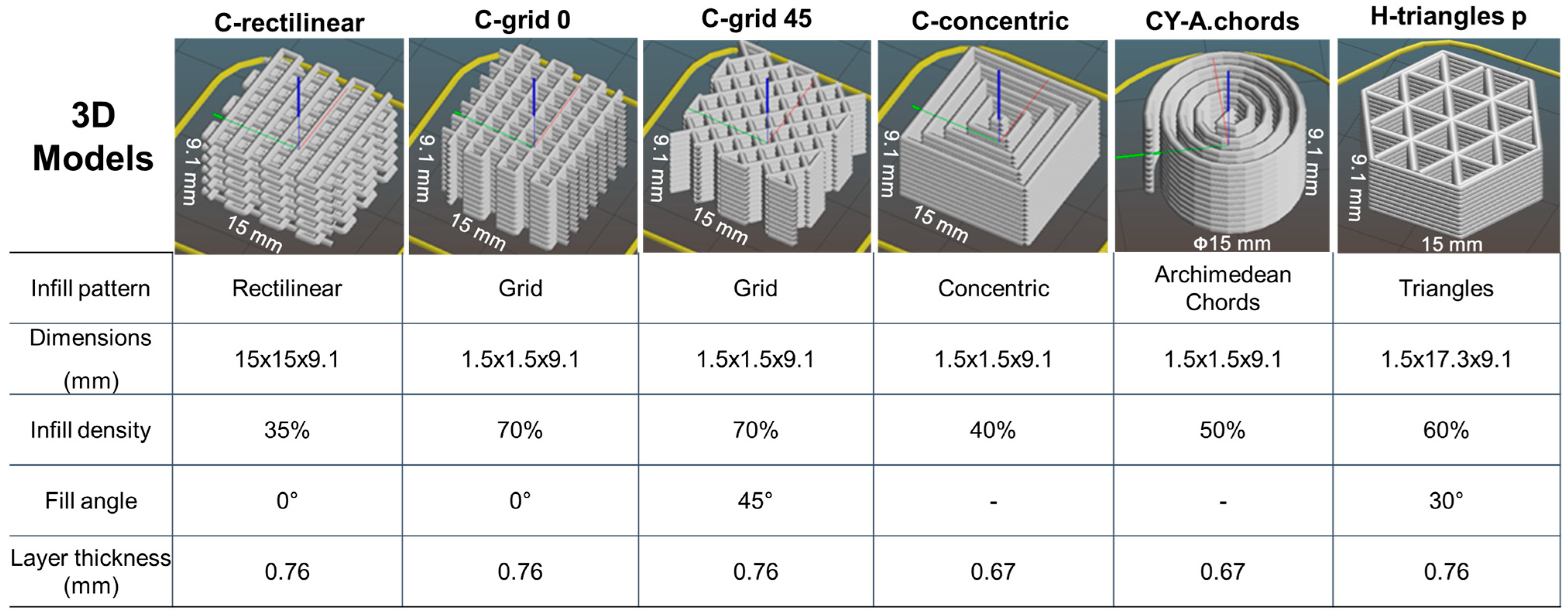
3.4.2. Effect of Specimen Geometry

For zirconia scaffolds with macropores, lower mechanical properties were found compared to samples with 100%. Introducing porosity into the geometry has decreased the strength and reduced the structural integrity of the zirconia.
On the other hand, the PICN pieces with different geometries have been investigated, Figure 9. The stress increased with the strain, and the stain–stress curves showed an approximate straight upward trend. A brittle failure mode was evidenced for all samples. Moreover, higher compression strength (160.1 ± 2.7 MPa) was achieved for the sample PICN CY-A.chords, followed by the PICN C-concentric and PICN H-triangles p. ones. Similar values were determined for the PICN C-grid 0 and PICN C-grid 45 samples. The lowest value (65.4 ± 6.8 MPa) was observed for the PICN C-rectilinear one. It is essential to point out that the C-grid 0 and C-grid 45 geometries maintain their structural integrity up to the maximum load limit of the equipment used, 10 KN.
Figure 10 displays the calculated vertical (eyy) strain distribution maps of the three representative samples under 2% strain. It pointed out that, regarding the C-rectilinear sample, the maximum strain area was developed at the bottom of the piece, being one of the edges. Failure initiates in a filament at the bottom and extends to the top face very quickly, as indicated by the red color in Figure 10a. Each layer had the filaments in one direction, which caused the strain to be heterogeneous. The complete breaking occurred under 65 MPa of compression strength. On the contrary, the multiple filament directions increased the deformation resistance of the samples, which contributed to homogenous strain distribution up to higher stress. At this point, the surface remained nominally intact for the CY-A.chords and H-triangles p. ones. The following section will give a detailed inspection of the fractured surfaces.

3.5. Failure Analysis

The fractured samples were inspected in detail to clarify the mechanical response as a function of geometry. Although the samples were stacked layer upon layer from the exterior, different levels of bonding between the successive layers were found. In the case of C-rectilinear, pronounced pores and the single filament direction per layer caused poor connection from the consecutive layers. The mechanical behavior of the C-rectilinear design is the least desirable. On the other hand, when filaments were printed in two directions per layer, the samples showed a higher compression level, i.e., lower porosity and increased bonding strength. The C-concentric and CY-A.chords design fractured at the polymer–ceramic interface, Figure 11. This effect was also inspected in H-p triangles but to a lesser extent. This finding implied that, based on the orientation of the filaments, specific defects can set a limit on the mechanical strength. It has been noted that the two geometries demonstrating the optimal mechanical performance, C-grid 0 and C-grid 45, maintain their structural integrity at the machine’s maximum load.
Ceramics samples with complex geometries infiltrated with polymer have been developed. The introduction of the polymer network played an important role in enhancing the mechanical properties of ceramics by retaining its structural integrity and preventing crack propagation. However, future work needs to be conducted in order to focus on its potential application in dental restoration. In this sense, the cell viability and reduced bacteria proliferation should be investigated in complex 3D-printed geometry.
Within the limitations of this study, we have successfully integrated a biocompatible adhesive copolymer with 3D-printed zirconia scaffolds with desired macropores to palliate crack propagation in PICN scaffolds. The PICN samples studied displayed a good correlation between manufacturing design and structural integrity. By adding the polymer phase, the density of PICNs was lower than that of ceramic material with 100% infill, while the composites exhibited a large improvement in energy absorption than the respective scaffolds and parts with 100% infill. This improves clinical adaptation and comfort.

4. Conclusions

To assess the impact of printing design on mechanical properties, 3Y zirconia based on PICN ceramic samples have been produced by DIW. From the experimental results reported and discussed above, the following findings may be concluded:
(1)
Phase transformation was detected after sintering, compared to as-received ceramic powder. The tetragonal phase became predominant, accounting for approximately 100%, whereas the monoclinic one significantly decreased;
(2)
The feasibility of fabricating zirconia scaffolds with dimensionally stable and various geometries has been proven. The printing defects observed in the scaffolds mainly depend on the type of geometry of the samples;
(3)
Copolymer infiltration was more significant than 80% for all the geometries studied, reaching 95% for CY-A.chords. The presence of polymer in the PICN samples reduced the effect of the defects observed in the scaffolds;
(4)
PICN samples were more capable of withstanding higher stresses. The C-grid 0 and C-grid 45 geometries had the highest compression stress.

Author Contributions

Conceptualization, G.F. and L.L.; methodology, P.P.; software, J.Z., P.P., M.Y. and S.E.; validation, J.Z., P.P. and L.H.; formal analysis, J.Z. and G.F.; investigation, J.Z., P.P., L.H., J.-M.C. and E.A.; resources, G.F. and L.L.; data curation, P.P.; writing—original draft preparation, J.Z.; writing—review and editing, J.Z. and G.F.; visualization, G.F.; supervision, G.F.; project administration, G.F.; funding acquisition, G.F. and L.L. All authors have read and agreed to the published version of the manuscript.

Funding

This work was partly funded by the Spanish Government (Ministerio de Ciencia e Innovación) through the project PID2022-137274NB-C32. J. Zhang would like to acknowledge the China Scholarship Council (CSC) for its financial support (No. 201706740094).

Institutional Review Board Statement

Not applicable.

Informed Consent Statement

Not applicable.

Data Availability Statement

Upon request to the corresponding authors.

Acknowledgments

This work was partially supported by the Spanish Government (Ministerio de Ciencia e Innovación) under the project PID2022-137274NB-C32. J. Zhang appreciates the funding from the China Scholarship Council (CSC, No. 201706740094).

Conflicts of Interest

The authors declare no conflicts of interest.

References

  1. ASTM52900-15; Standard Terminology for Additive Manufacturing—General Principles—Terminology. ASTM International: West Conshohocken, PA, USA, 2015.
  2. Sodeyama, M.K.; Ikeda, H.; Nagamatsu, Y.; Masaki, C.; Hosokawa, R.; Shimizu, H. Printable PICN composite mechanically compatible with human teeth. J. Dent. Res. 2021, 100, 1475–1481. [Google Scholar] [CrossRef]
  3. Danforth, S.C. Fused deposition of ceramics: A new technique for the rapid fabrication of ceramic components. Mater. Technol. 1995, 10, 144–146. [Google Scholar] [CrossRef]
  4. Xing, H.; Zou, B.; Liu, X.; Wang, X.; Chen, Q.; Fu, X.; Li, Y. Effect of particle size distribution on the preparation of ZTA ceramic paste applying for stereolithography 3D printing. Powder Technol. 2020, 359, 314–322. [Google Scholar] [CrossRef]
  5. Zhang, K.; He, R.; Ding, G.; Bai, X.; Fang, D. Effects of fine grains and sintering additives on stereolithography additive manufactured Al2O3 ceramic. Ceram. Int. 2021, 47, 2303–2310. [Google Scholar] [CrossRef]
  6. Miao, G.; Du, W.; Moghadasi, M.; Pei, Z.; Ma, C. Ceramic binder jetting additive manufacturing: Effects of granulation on properties of feedstock powder and printed and sintered parts. Addit. Manuf. 2020, 36, 101542. [Google Scholar] [CrossRef]
  7. Du, W.; Singh, M.; Singh, D. Binder jetting additive manufacturing of silicon carbide ceramics: Development of bimodal powder feedstocks by modeling and experimental methods. Ceram. Int. 2020, 46, 19701–19707. [Google Scholar] [CrossRef]
  8. Ratsimba, A.; Zerrouki, A.; Tessier-Doyen, N.; Nait-Ali, B.; André, D.; Duport, P.; Neveu, A.; Tripathi, N.; Francqui, F.; Delaizir, G. Densification behaviour and three-dimensional printing of Y2O3 ceramic powder by selective laser sintering. Ceram. Int. 2021, 47, 7465–7474. [Google Scholar] [CrossRef]
  9. Sun, J.; Chen, X.; Wade-Zhu, J.; Binner, J.; Bai, J. A comprehensive study of dense zirconia components fabricated by additive manufacturing. Addit. Manuf. 2021, 43, 101994. [Google Scholar] [CrossRef]
  10. Hodásová, L.; Sans, J.; Molina, B.G.; Alemán, C.; Llanes, L.; Fargas, G.; Armelin, E. Polymer infiltrated ceramic networks with biocompatible adhesive and 3D-printed highly porous scaffolds. Addit. Manuf. 2021, 39, 101850. [Google Scholar] [CrossRef]
  11. Martínez-Vázquez, F.J.; Sánchez-González, E.; Borrero-López, O.; Miranda, P.; Pajares, A.; Guiberteau, F. Novel bioinspired composites fabricated by robocasting for dental applications. Ceram. Int. 2021, 47, 21343–21349. [Google Scholar] [CrossRef]
  12. Hodásová, L.; Morena, A.G.; Tzanov, T.; Fargas, G.; Llanes, L.; Alemán, C.; Armelin, E. 3D-printed polymer-infiltrated ceramic network with antibacterial biobased silver nanoparticles. ACS Appl. Bio Mater. 2022, 5, 4803–4813. [Google Scholar] [CrossRef]
  13. Zhang, D.; Peng, E.; Borayek, R.; Ding, J. Controllable ceramic green-body configuration for complex ceramic architectures with fine features. Adv. Funct. Mater. 2019, 29, 1807082. [Google Scholar] [CrossRef]
  14. Conrad, H.J.; Seong, W.J.; Pesun, I.J. Current ceramic materials and systems with clinical recommendations: A systematic review. J. Prosthet. Dent. 2007, 98, 389–404. [Google Scholar] [CrossRef]
  15. Denry, I.; Kelly, J.R. State of the art of zirconia for dental applications. Dent. Mater. Off. Publ. Acad. Dent. Mater. 2008, 24, 299–307. [Google Scholar] [CrossRef]
  16. Eldafrawy, M.; Nguyen, J.-F.; Mainjot, A.K.; Sadoun, M.J. A functionally graded PICN material for biomimetic CAD-CAM blocks. J. Dent. Res. 2018, 97, 1324–1330. [Google Scholar] [CrossRef]
  17. Coldea, A.; Swain, M.V.; Thiel, N. Mechanical properties of polymer-infiltrated-ceramic-network materials. Dent. Mater. 2013, 29, 419–426. [Google Scholar] [CrossRef]
  18. Saláta, J.; Szabó, F.; Csuti, P.; Antal, M.; Márton, P.; Hermann, P.; Borbély, J.; Ábrám, E. Effect of thickness, translucency, and substrates on the masking ability of a polymer-infiltrated ceramic-network material. J. Esthet. Restor. Dent. 2023, 35, 886–895. [Google Scholar] [CrossRef]
  19. Facenda, J.C.; Borba, M.; Corazza, P.H. A literature review on the new polymer-infiltrated ceramic-network material (PICN). J. Esthet. Restor. Dent. 2018, 30, 281–286. [Google Scholar] [CrossRef]
  20. Li, K.; Kou, H.; Rao, J.; Liu, C.; Ning, C. Fabrication of enamel-like structure on polymer-infiltrated zirconia ceramics. Dent. Mater. 2021, 37, 245–255. [Google Scholar] [CrossRef]
  21. Ikemoto, S.; Nagamatsu, Y.; Masaki, C.; Hosokawa, R.; Ikeda, H. Development of zirconia-based polymer-infiltrated ceramic network for dental restorative material. J. Mech. Behav. Biomed. Mater. 2023, 150, 106320. [Google Scholar] [CrossRef]
  22. Hodásová, L.; Alemán, C.; Del Valle, L.J.; Llanes, L.; Fargas, G.; Armelin, E. 3D-printed polymer-infiltrated ceramic network with biocompatible adhesive to potentiate dental implant applications. Materials 2021, 14, 5513. [Google Scholar] [CrossRef]
  23. Li, J.; Cui, B.; Lin, Y.; Deng, X.; Li, M.; Nan, C. High strength and toughness in chromatic polymer-infiltrated zirconia ceramics. Dent. Mater. 2016, 32, 1555–1563. [Google Scholar] [CrossRef]
  24. Shahzad, A.; Lazoglu, I. Direct ink writing (DIW) of structural and functional ceramics: Recent achievements and future challenges. Compos. Part B Eng. 2021, 225, 109249. [Google Scholar] [CrossRef]
  25. Zhang, J.; Yarahmadi, M.; Cabezas, L.; Serra, M.; Elizalde, S.; Cabrera, J.M.; Llanes, L.; Fargas, G. Robocasting of dense 8Y zirconia parts: Rheology, printing, and mechanical properties. J. Eur. Ceram. Soc. 2022, 43, 2794–2804. [Google Scholar] [CrossRef]
  26. Tosoh Tosoh Zirconia Brochure. Available online: https://www.rbhltd.com/wp-content/uploads/2019/05/Tosoh-Zirconia-Brochure.pdf (accessed on 21 March 2022).
  27. Yarahmadi, M.; Barcelona, P.; Fargas, G.; Xuriguera, E.; Roa, J.J. Optimization of the ceramic ink used in direct ink writing through rheological properties characterization of zirconia-based ceramic materials. Ceram. Int. 2022, 48, 4775–4781. [Google Scholar] [CrossRef]
  28. Toraya, H.; Yoshimura, M.; Somiya, S. Calibration curve for quantitative analysis of the monoclinic-tetragonal ZrO2 system by X-ray diffraction. J. Am. Ceram. Soc. 1984, 67, C-119–C-121. [Google Scholar] [CrossRef]
  29. Awwad, A.M.; Salem, N.M.; Abdeen, A.O. Biosynthesis of silver nanoparticles using Olea europaea leaves extract and its antibacterial activity. Nanosci. Nanotechnol. 2012, 2, 164–170. [Google Scholar] [CrossRef]
  30. Wang, F.; Teng, X.; Hu, X.; Jiang, Y.; Guo, X.; Li, L.; Liu, X.; Liu, X.; Lu, H. Damage and failure analysis of a SiCf/SiC ceramic matrix composite using digital image correlation and acoustic emission. Ceram. Int. 2022, 48, 4699–4709. [Google Scholar] [CrossRef]
  31. Biegler, M.; Graf, B.; Rethmeier, M. In-situ distortions in LMD additive manufacturing walls can be measured with digital image correlation and predicted using numerical simulations. Addit. Manuf. 2018, 20, 101–110. [Google Scholar] [CrossRef]
  32. Isaac, J.P.; Dondeti, S.; Tippur, H.V. Crack initiation and growth in additively printed ABS: Effect of print architecture studied using DIC. Addit. Manuf. 2020, 36, 101536. [Google Scholar] [CrossRef]
  33. Pan, B.; Qian, K.; Xie, H.; Asundi, A. Two-dimensional digital image correlation for in-plane displacement and strain measurement: A review. Meas. Sci. Technol. 2009, 20, 62001. [Google Scholar] [CrossRef]
  34. Dong, Y.L.; Pan, B. A review of speckle pattern fabrication and assessment for digital image correlation. Exp. Mech. 2017, 57, 1161–1181. [Google Scholar] [CrossRef]
  35. Périé, J.N.; Calloch, S.; Cluzel, C.; Hild, F. Analysis of a multiaxial test on a C/C composite by using digital image correlation and a damage model. Exp. Mech. 2002, 42, 318–328. [Google Scholar] [CrossRef]
  36. Bastawros, A.F.; Bart-Smith, H.; Evans, A.G. Experimental analysis of deformation mechanisms in a closed-cell aluminum alloy foam. J. Mech. Phys. Solids 2000, 48, 301–302. [Google Scholar] [CrossRef]
  37. Wattrisse, B.; Chrysochoos, A.; Muracciole, J.M.; Némoz-Gaillard, M. Analysis of strain localization during tensile tests by digital image correlation. Exp. Mech. 2001, 41, 29–39. [Google Scholar] [CrossRef]
  38. Lo, C.; Sano, T.; Hogan, J.D. Microstructural and mechanical characterization of variability in porous advanced ceramics using X-ray computed tomography and digital image correlation. Mater. Charact. 2019, 158, 109929. [Google Scholar] [CrossRef]
  39. Bannunah, A.M. Biomedical applications of zirconia-based nanomaterials: Challenges and future perspectives. Molecules 2023, 28, 5428. [Google Scholar] [CrossRef]
  40. Tovar-Vargas, D.; Turon-Vinas, M.; Anglada, M.; Jimenez-Pique, E. Enhancement of mechanical properties of ceria-calcia stabilized zirconia by alumina reinforcement. J. Eur. Ceram. Soc. 2020, 40, 3714–3722. [Google Scholar] [CrossRef]
  41. Yarahmadi, M.; Roa, J.J.; Zhang, J.; Cabezas, L.; Ortiz-Membrado, L.; Llanes, L.; Fargas, G. Micromechanical properties of yttria-doped zirconia ceramics manufactured by direct ink writing. J. Eur. Ceram. Soc. 2022, 43, 2884–2893. [Google Scholar] [CrossRef]
  42. Kitano, Y.; Mori, Y.; Ishitani, A.; Masaki, T. Rhombohedral phase in Y2O3-partially-stabilized ZrO2. J. Am. Ceram. Soc. 1988, 71, C-34–C-36. [Google Scholar] [CrossRef]
  43. Slotwinski, J.A.; Garboczi, E.J.; Hebenstreit, K.M. Porosity measurements and analysis for metal additive manufacturing process control. J. Res. Natl. Inst. Stand. Technol. 2014, 119, 494. [Google Scholar] [CrossRef] [PubMed]
Figure 1. Schematic diagram of direct ink writing of scaffolds and preparation of PICNs.
Ceramics 07 00028 g001
Figure 2. Three-dimensional models of samples shaped by DIW with different manufacturing designs.
Ceramics 07 00028 g002
Figure 3. (a) SEM micrograph of 3Y-ZrO2 powder; (b) Particle size distribution histogram from the SEM image; (c) SEM micrograph of sintered zirconia sample; (d) Grain size distribution obtained from image (c).
Ceramics 07 00028 g003
Figure 4. XRD spectra of zirconia powder and 3D–printed zirconia scaffold. t: tetragonal ZrO2, m: monoclinic ZrO2 phases.
Ceramics 07 00028 g004
Figure 5. Top view of the sintered zirconia samples with different manufacturing designs: (a) C-rectilinear, (b) C-grid 0°, (c) C-grid 45°, (d) C-concentric, (e) CY-A. Chords, and (f) H-triangles p.
Ceramics 07 00028 g005
Figure 6. The pore size of the sintered zirconia scaffolds with different manufacturing designs: (a) C-rectilinear, (b) C-grid 0°, (c) C-grid 45°, (d) C-concentric, (e) CY-A.chords, and (f) H-triangles p.
Ceramics 07 00028 g006
Figure 7. Tomographic analysis of sintered zirconia samples with different manufacturing designs: (a1,a2) C-rectilinear, (b1,b2) C-grid 0°, (c1,c2) C-concentric, (d1,d2) CY-A.chords, and (e1,e2) H-triangles p.
Ceramics 07 00028 g007
Figure 8. Photograph of 3D-printed PICN with different manufacturing designs: (a) C-grid 45, (b) C-concentric, and (c) H-triangles p. The pores represent the Bis-GMA/TEGDMA copolymer coating and filling materials.
Ceramics 07 00028 g008
Figure 9. Stress–strain curves for PICN specimens with different geometry.
Ceramics 07 00028 g009
Figure 10. Strain distribution under 2% strain for PICN specimens with different printing designs obtained from DIC: (a) C-rectilinear, (b) CY-A.chords, and (c) H-triangles p.
Ceramics 07 00028 g010
Figure 11. Optical images of fractured PICN samples with different geometries.
Ceramics 07 00028 g011
Table 1. The properties of starting 3Y-ZrO2 powder.
Typical Properties3Y-ZrO2
Particle size (nm)90
Specific surface area (m2/g)7 ± 2
Density ρ T (g/cm3)6.05
Bending strength 1 (MPa)1200
Hardness 2 (HV 10)1250
1 Three-point bending test. 2 Applied load of 98.07 N.
Table 2. Phase composition and crystalline size for 3Y-ZrO2 powder and sintered samples.
PhaseVx (%)2θ (°)β (rad)cos (θ)D (nm)
PowderTetragonal~68300.0050.96530
Monoclinic~32280.0060.9722
Sintered samplesTetragonal~100300.0030.96648
Monoclinic-----
Table 3. Properties of 3D-printed zirconia scaffolds and the ones with copolymer infiltrated.
Sample3D-Printed Zirconia Scaffold 3D-Printed Zirconia with Copolymer Infiltrated (PICN)
Shrinkage Density (g/cm3)Infiltration (%)
C-rectilinear 31.4 ± 3.35.79 ± 0.0489.6 ± 0.7
C-grid 031.4 ± 1.25.72 ± 0.1393.0 ± 0.5
C-grid 4528.9 ± 0.85.66 ± 0.1591.3 ± 1.3
C-concentric29.3 ± 1.55.75 ± 0.0290.7 ± 0.2
CY-A.chords27.3 ± 2.85.72 ± 0.0794.9 ± 3.5
H-triangles p.30.6 ± 1.35.74 ± 0.0484.7 ± 9.6
Table 4. Stress–strain data from the compression test of 3D-printed zirconia scaffolds and the ones with copolymer infiltrated.
Sampleσmax (MPa)εcompression (%)
Zirconia scaffoldsC-rectilinear4.5 ± 0.82.6 ± 0.7
C-grid 056.4 ± 13.12.4 ± 0.2
C-grid 4562.7 ± 3.03.5 ± 0.1
C-concentric31.8 ± **3.2 ± **
CY-A.Chords61.7 ± 7.42.3 ± 1.0
H-triangles p.36.0 ± 8.12.4 ± 0.5
PICN hybrid materialsPICN C-rectilinear65.4 ± 6.83.1 ± 0.1
PICN C-grid 071.6 ± 2.22.5 ± 0.3
PICN C-grid 4568.7 ± 0.12.6 ± 1.0
PICN C-concentric94.6 ± 0.62.7 ± 0.6
PICN CY-A.Chords160.1 ± 2.72.2 ± *
PICN H-triangles p.80.9 ± *2.0 ± *
Samples with 100%C-100%56.0 ± 7.53.8 ± 0.3
CY-100%92.4 ± **2.2 ± **
H-100%48.1 ± **5.7 ± **
* Values at 10 KN for unbroken pieces. ** Values without standard deviation due to errors during compression tests.
Disclaimer/Publisher’s Note: The statements, opinions and data contained in all publications are solely those of the individual author(s) and contributor(s) and not of MDPI and/or the editor(s). MDPI and/or the editor(s) disclaim responsibility for any injury to people or property resulting from any ideas, methods, instructions or products referred to in the content.

