
Study on Membrane Damage and Collapse of Air-Supported Structures under Fire Conditions

1
Faculty of Architecture, Civil and Transportation Engineering, Beijing University of Technology, Beijing 100124, China
2
Multi-Functional Shaking Tables Laboratory, Beijing University of Civil Engineering and Architecture, Beijing 100044, China
*
Author to whom correspondence should be addressed.
Fire 2022, 5(5), 162; https://doi.org/10.3390/fire5050162
Submission received: 17 September 2022
/
Revised: 2 October 2022
/
Accepted: 4 October 2022
/
Published: 8 October 2022
(This article belongs to the Section Fire Risk Assessment and Safety Management in Buildings and Urban Spaces)
Abstract
:Air-supported structures are widely used as public buildings. Air-supported structures are soft and most traditional fire-fighting installations cannot be used in them. Existing design specifications only specify the fire resistance of the materials to be used for air-supported structures and there is no fire resistance design method for air-supported structures. The destruction process of air-supported structures can be divided into three stages: pre-fracture, leakage, and collapse. Theorical and numerical models were used to research the time span of all those stages. A framework to estimate the collapse and evacuation time was proposed in this paper. Air-supported structures with different spans were researched in this paper, and we found that the height of a structure has a significant influence on its fire resistance. The evacuation time increased by more than 52 times when the structure’s span increased from 20 m to 80 m. The pre-fracture stage contributed to more than 90% of the evacuation time when the span of structure was larger than 80 m.
1. Introduction
Air-supported structures are inexpensive, light, and easy to construct. Because of these characteristics, air-supported structures are generally used for the construction of warehouses, stadiums, and malls [1]. The air-supported structure is borne by the pressure difference inside and outside the structure; therefore, it is possible to build large spans of space without any columns. Air-supported structures usually consist of a foundation, membrane, cable net, door, and fan system (see Figure 1).
Current fire resistance design methods and standards for buildings are only suitable for traditional structures, such as steel or concrete structures. The deformation of these structures under the design load is very small. Unlike traditional structures, air-supported structures are soft and light. Therefore, fireproofing design methods and codes cannot be directly used in air-supported structures.
There are some differences between traditional and air-supported structures:
- Traditional fireproofing systems, such as automatic spraying systems, cannot be used in air-supported structures;
- The air-supported membrane structure cannot be separated by a firewall, so air-supported structures are mostly used as an entire fire partition. However, the indoor areas of air-supported structures generally exceed the area of the fire zone allowed by safety codes;
- In order to ensure the sealing performance of an air-supported structure, air-supported structures usually use revolving doors for personnel entrances and exits and airlock gates for the entrance and exit of automobiles and other large machines. However, revolving doors and airlock gates cannot be used as emergency exits;
- Damage to unstructured walls is allowed in traditional structures. However, any membrane damage in air-supported structures may lead to the collapse of the entire structure.
There are some codes for the design and construction of air-supported structures, such as The Air-Supported Structures by ASCE and The Technical Specification of Membrane Structures by CECS. The Air-Supported Structures required that all the membranes used in air-supported structures meet the fire-resistance capacity in the code and limited the number of people that could be accommodated in the air-supported structure [2]. The Technical Specification of Membrane Structures required that incombustible membranes be used in air-supported structures [3]. All the above specifications only specify the materials used in the air-supported structure but do not give design methods for the fire performance of the air-supported structure.
The shape of air-supported structures is usually hyperboloid, and there are different heights at different locations. The temperature and smoke diffusion properties of long-span dome buildings are different from ordinary buildings [4,5,6]. Long-span buildings usually have greater height and volume; therefore, in the event of a fire, the heating rate of long-span buildings is significantly slower than that of ordinary buildings. When a fire occurs in a structure with a tall interior space, the roof is cooler than a normal building and has a smaller temperature gradient except for a small area directly above the source of the fire. The temperature of the roof above the source of the fire decreases significantly with the increasing height of the building. There are several studies about the temperature and smoke diffusion properties of air-supported structures. Wu [7] researched the temperature of air-supported structures in the event of a fire using FSI models and proposed that the deformation of the structure during a fire is small enough not to have a significant effect on indoor temperatures and smoke. There are also studies about the temperatures of membrane structures in the event of a fire based on different engineering methods [8,9]. Existing research mostly focuses on indoor temperature and visibility using cellular automata. Zhang [10] researched the temperature of air-supported structures and proposed the function between location and temperature. Zhang also proposed the impact of the rise-span and length-width ratios. Cheng [11] researched air-supported coal bunkers in the event of a fire and proposed a relationship between temperature and location. Cheng also studied the internal temperature of air-borne membrane structures in the presence of fires of multiple origins and proposed that the indoor temperature in a multi-origin fire load case can be obtained by superimposing multiple single-origin fire models. Areas of structural heights greater than 5 m are less likely to burn through in the event of a fire; therefore, stricter fire-prevention measures should be applied to areas of structural heights less than 5 m. In these studies, the membrane surfaces of air-supported structures are regarded as homogeneous surfaces without welded joints. However, a membrane structure is usually composed of several pieces of membrane and is typically connected by stitched, welding, and glue joints, or a special connector. Weld joints are heavily used because they are water resistant and easy to operate. High temperatures can soften the coating and fabric, thus significantly changing the mechanical properties of the coated fabric. Zhao [12] researched the strength of weld joints and obtained the strength of weld seams at temperatures between 20 °C and 70 °C, and proposed the minimum lap width, which can meet the design strength requirements at 70 °C. Xue [13] researched the strength of a membrane with weld joints at high temperatures. The strength of an unsymmetrical weld joint was also researched by Xue. The surface temperature of the membrane structure can reach 70 °C under sunlight in tropical countries [14], and it can catch fire when the temperature exceeds 250 °C. The strength of the welded joints in the membrane is significantly lower than that of the membrane at high temperatures. Therefore, it is necessary to research the fracture of the membrane with weld joints in fire conditions.
Breakage of membranes and welded joints does not mean that the structure will immediately collapse. Due to the small dead weight of the membrane, the collapse of the air-supported structure is a slow process. It can take minutes or even hours for the structure to start leaking and finally collapse [15]. Xue [16] researched the collapse of air-supported structures and proposed the numerical method of the air–structure interaction.
Zhou [17] and Blomqvist [18] researched small-scale cuboid structures in fire events using CFD models. The membrane breaks out quickly when the fire is near the wall; however, the tested structure remained intact for a longer period of time when the fire was away from the wall. Membranes with various coatings and fabrics were used in Blomqvist’s research. Silicone, PVC, and PTFE coatings were used in the research in addition to polyester and fiberglass fabric. None of the membranes used in the experiments met the standard for noncombustible building materials but the silicone-coated fiberglass fabrics produced the least smoke in a fire event.
Up to now, theoretical and numerical calculation methods cannot perfectly explain the behavior of air-supported membrane structures from the beginning of a fire to the final collapse. An experimental study is the main method to study the mechanical behaviors of membrane structures under fire conditions. There are several experimental studies about fires in air-supported structures. Custer [19] researched the indoor temperatures and failure of the membrane of a small air-supported structure with a plane size of 20 ft ∗ 20 ft in the event of a fire. Homogeneous polyethylene (PE) and coated-glass-fiber membranes were used in the research. The most common failure mode is that the membrane melted under the fire when the PE membranes were used. The failure when the glass-fiber-coated membrane was used is significant shear deformation. The membrane used for an air-supported structure is very thin; therefore, the membrane has low thermal resistance. The temperature near the membrane was lower than 1ft below the membrane because the membrane was cooled by the outdoor air. Hopkinson [20] researched the failure and collapse of air-supported structures in the event of a fire. A 19 m × 9 m × 4 m air-supported structure with a PVC-coated nylon membrane was used in Hopkinson’s research. Fires with three different powers were used in the research. When the fire’s power is low, the membrane above the fire fails, but the structure can still be stable. On the contrary, when the power of the fire is high, the structure quickly collapses. However, most of the above tests are very old, and the membrane materials used in the tests are completely different from those used in modern air-supported structures.
There are few studies about the overall collapse process of air-supported structures in the event of a fire, and there are no fire-resistance methods used in designs. Therefore, it is important to research the failure and collapse of air-supported structures in the event of a fire, thereby improving the fire-resistance design methods of air-supported structures. The destruction of air-supported structures in a fire can be divided into three stages: pre-membrane fracture, leakage, and collapse. Theorical and numerical models were used to research the fracture and collapse of air-supported structures in this paper. The collapse and evacuation times of air-supported structures are given in this paper.
2. Temperature of Air-Supported Structure in Event of Fire
When studying the safety of air-supported structures in fire conditions, it is necessary to first study the temperature of the structure in fire conditions. Using the calculated resulting temperatures, the safety of the structure can be studied. CFD models were built to research the temperatures in air-supported structures. ANSYS-CFX was used to research the temperatures of the structure.
2.1. Geometry and Mesh
A geometry model was built to research the temperatures of air-supported structures. The size of the model is 38 m × 20 m × 7 m. The deformation of the structure will not have a significant effect on the indoor gas-flow regularity in the fire event [7]; therefore, unidirectional fluid–structure interaction analysis is used in the model. The cooling effect of outdoor air on the membrane and indoor air was simulated by setting the convective heat-transfer coefficient outside the membrane. The model used in our research is shown in Figure 2. The model was meshed to the tetrahedron elements. The sizes of the elements are 0.05 m, and there are 618,793 elements used to simulate the indoor air.
2.2. Material and Boundary
The k-ε turbulence method was used to simulate the air. The initial temperature is 0 °C while the initial pressure difference is 200 Pa. The initial density is 1.29 kg/m3.
The burning part of a fire is a circle in the center of the ground whose diameter is 2 m. The fire was simulated by a surface heat source with black-body radiation.
The ground was surrounded by a smooth adiabatic surface. The thin-material model was used to simulate the membrane. The thickness of the membrane is 1.04 mm while the thermal resistance is 0.14 K* m/W. The convective heat-transfer coefficient between the outer surface of the membrane and the outdoor air is 16 W/m2K. The Monte Carlo radiation heat-transfer method was used to simulate the thermal radiation. The thermal radiation was simplified to the emission, reflection, absorption, and scattering of a large number of photons in the Monte Carlo method. Stable statistical results are obtained by tracking a large number of photons [21].
The fan system was controlled by the control system to make the pressure difference stay at 200 Pa. The maximum air-supply capacity of the fan system is 5000 m3/h. The fan system was linked with the structure by a Φ500 mm circular hose. The velocity of fresh air from the fan can be expressed by:
where Vinlet is the velocity of fresh air, P is the design pressure difference, and ρ is the density of air. The value of ρ is 1.29 kg/m3.
Even though there is no failure in the structure, the indoor air still keeps losing through gaps. These gaps can be equivalent to a hole in the structure. A circle hole was set in the center of the membrane to simulate the air loss. The amount of lost air varies with differences in pressure. The initial equivalent leakage area is usually used to express the rate of gas loss through the gap. Different backpressure was set to simulate the changes in the initial equivalent leakage area. With the backpressure, the mass of the air leaked through the imaginary hole is equal to the real air lost through the gap. The real and equivalent air-loss velocities can be expressed by:
Therefore, the backpressure can be expressed by:
The initial equivalent leakage area was solved by the method in reference [16].
The principles and processes of fuel combustion are very complex and difficult to accurately describe when constructing building-fire models. Most of the existing building-fire models only consider the heat-release process and smoke diffusion of the fire without considering the combustion reaction. Building fire can be divided into four stages: the initiation, growth, full-development, and decline stages. The power of the fire grows quickly in the initiation and growth stages and keeps stable at the full-development stage. The power of the fire can be expressed by:
where Q is the power of fire, Qmax is the maximum power of fire, t is time, and t0 is the target time. α in the Eq can be expressed by:
The parameter in Equation (5) when the power of the fire is 1 MW is shown in Table 1.
All the types of fire were used in the model. The total time in the model is 1200 s and automatic instrumentation was used. The initial step length is 0.1 s and the maximum step length is 1 s. The power of fire used in the model is shown in Figure 3. The power increased to the maximum, accelerated, and then maintained at maximum power. There is no decline stage in the fire model.
2.3. Results
The CFD model was solved and the temperature on the section of the structures is shown in Figure 4, Figure 5, Figure 6 and Figure 7. There is a high-temperature region above the fire at the start. As the fire develops, hot air accumulates at the top. The hot air layer at the top thickens and heats up over time.
The temperature of the membrane above the fire is shown in Figure 8. The heat-up rate of different models is different at the start. When the power increased to the maximum power, the heat-up rate is similar; however, the temperature is different.
3. Failure of the Air-Supported Structure in the Fire Event
The failure of air-supported structures can be divided into three stages: the membrane failure, strain relaxes, and the collapse stages. The membrane is air-proofed at the first stage. When the membrane starts to fail, the air leakage in the structure to the outside is driven by the pressure difference between the indoor and outdoor environments, in addition to the strain release of the membrane. In the last stage, the air leakage is driven by the deformation of the structure.
3.1. Strength of Membrane at High Temperature
The temperature of the membrane increases in the event of a fire, which means the membrane may fail. The CFD in the second chapter can be used to solve the temperature of the structures. The structure may fail at the membrane or the weld joint. The method to check the strength of the membrane in Technical Specifications for Membrane Structures is:
where σmax is the maximum principal stress of the membrane, γ is the partial safety factor for resistance, ξ is the strength reduction factor, and f is the strength of the membrane.
The probability of fire in air-supported membrane structures is very small, so only the basic load case was checked in this paper. Special conditions such as strong winds and heavy snow were not researched. In high temperatures, Equation (6) can be expressed by:
where ζ(T) can be expressed by:
where T is temperature, t0 is the reference temperature, and the value of t0 is 23 °C.
Therefore, the safety factor of the membrane can be expressed by:
The strength ratios of the membrane and weld joints at high temperatures can be expressed by:
where fweld is the strength of the weld joint.
Therefore, the safety factor of the weld joint can be expressed by:
3.2. Failure of Air-Supported Structures at High Temperature
3.2.1. Geometry and Mesh
Finite element (FE) models were used to research the failure of air-supported structures. The shape and size of the models is the same as the one used in the CFD model. There are two modes of the failure of the weld joint: the peeling of the weld seam or failure of the membrane near the weld seam. The weld joint in the model included the weld seam and 50 mm on both sides of the weld seam. The FE model of the structures is shown in Figure 9. There are five weld joints that were set in the model.
The membrane was trimmed by the cable and weld joint, so the triangle mesh was used in the region near the weld joint and edge of the structure. Quadrilateral mesh was used in other regions. M3D3 and M3D4 elements were used to simulate the membrane. The T3D2 element was used to simulate the cables. M3D3 and M3D4 are the membrane elements and T3D2 is the truss element. All the elements are tensile-only. The F3D4 elements were used to simulate the air in the structure.
3.2.2. Material, Boundary, and Steps
PVC-coated PES-fabric membranes, whose thicknesses are 1.04 mm, were used in the structure. The anisotropic model was used to simulate the membrane. The property of the membrane is shown in Table 2.
There are five steps used to simulate the structure:
- (1)
- An implicit dynamic step—pressure difference was loaded in this step;
- (2)
- An implicit dynamic step—gravity was loaded in this step;
- (3)
- An implicit dynamic step—no new loads were added in this step. The vibration caused by loading gradually stops in this step;
- (4)
- A static step—all the vibrations were stopped and a static solution is found;
- (5)
- An implicit dynamic step—the temperature in the fire was loaded in this step. The step ended when the membrane started to fail.
The fast-grow fire model in Chapter 2 was used in the model. The temperature at every node was mapped from the CFD model to the FE Model. A user script was used in the model to solve the safety factors of the membrane and joint.
3.2.3. Result
The maximum principal stress of the structure bearing the pressure difference and gravity is shown in Figure 10. There is no pressure stress or wrinkle on the membrane. The temperature was mapped from the CFD model and shown in Figure 11.
The stress perpendicular to the welded joint is shown in Figure 12. There is only a small variation in stress before and during the fire. The maximum displacement changed from 92.70 mm to 97.77 mm.
The safety factor of the membrane and joint is shown in Figure 13. Under the pressure and gravity, the safe factor of the joint is smaller than the membrane around the significant joint. The minimum safety factor of the joint is 4.04 before the fire and 0.44 after the fire.
The failure area of the joint is on the center of the structure. The middle part of the air-supported structure can be considered as a cylindrical shell. The stress along the long and short axials are 0 MPa and 0 MPa, respectively. The Westergaard function was used to solve the displacement of the membrane near the crack tip. The displacement of the membrane near the crack tip can be expressed by:
where a is half of the crack length. x and y are the coordinates of the point. G is shear modulus of the membrane and σy is the stress in the long axial direction. k can be solved by:
As illustrated in Equation (12), the projection shape of the crack is an ellipse. The area of the projection of the crack can be expressed by:
The area of the crack can be expressed by:
where the R can be expressed by:
According to the result of the FE model and Equation (11), the weld joint above the fire failed at 134 °C.
The length of the crack in Figure 13 is 150 mm. The area of the crack under pressure difference and gravity is 0.061 m2.
The temperature of the weld joint above the fire is shown in Figure 14. The horizon line in Figure 14 is the failure temperature when the structure is under the pressures of difference and gravity.
The failure time when there are different fire growth rates is shown in Figure 15. As illustrated in the figure, the failure time is 672.6 s with a very-fast-growth fire and 1021.2 s with a slow-growth fire.
4. Leakage of the Air-Supported Structures
The air-supported structure can keep its shape if the membrane does not break in the event of fire. Therefore, the fire-prevention design method of the traditional structure can also be used in air-supported structures. If there is a risk of the breaking of the membrane, the impacts of leakage and collapse should be considered in the fire-prevention design of the structure. According to Bernoulli’s law, the allowable leakage area of the structure when the fan worked at the maximum flow rate can be expressed by:
where Aallow is the allowable leakage area, Vfan is the capacity of the fan, Pcr is the minimum allowable pressure difference, and the value of Pcr is 25 Pa.
The allowable equivalent leakage is 0.82 m2. The revolving and air-lock door cannot be used as an emergency exit in the fire event. The area is bigger than the allowable leakage area so the structure will collapse if the emergency door is opened. It is necessary to research the collapse properties of air-supported structures.
4.1. Leakage and Collapse of Air-Supported Structures
The shape of the structure can be considered unchanged in the strain relax stage, and the pressure difference can be considered unchanged in the collapse stage.
The leakage rate of air-supported structures can be expressed by:
where P is the pressure difference, ρ is density of air, and v is velocity of air leakage.
The mass-loss rate of the structures can be expressed by:
where m is the mass of indoor air and A is the leakage area.
Equation (20) can be expressed by:
where T is temperature, M is the mole mass of air, and V is the volume of the structure.
The time span of the leakage stage is very short, so the change of T in the strain relax stage is small. T can be assumed as a constant. Therefore, the indoor air mass in the strain relax stage can be expressed by:
where m0 is the initial mass of indoor air, and m0 can be expressed by:
where Pref is the reference pressure, and the value of Pref is 101 kPa.
At the collapse stage, the pressure difference changes slowly. Therefore, it can be assumed that the pressure difference is not changed in the collapse stage. The loss rate of volume can be expressed by:
The density of the air changed when the temperature changed, and Equation (24) can be expressed by:
where ρ0> and T0 are the initial density and temperature, respectively.
The temperature continuously increases in the process of collapse. The upper and lower bounds of the real collapse time is the collapse at the starting collapse temperature and the ending collapse temperature. When the average of the collapse time span is solved by the starting and ending collapse temperatures, the absolute and relative errors can be expressed by:
where Errorabs and Errorrel are absolute and relative errors, respectively, ρ0 is initial density, and ρf is final density. Based on the CFD model, the average temperature when the structure starts to fail is 67 °C, and the relative error of the collapse solved by Equation (25) is less than 4%.
4.2. CFD Model of the Leakage Stage
CFD models, which were the same as the ones in Chapter 2, were used to research the strain relax stage. There is an outlet on the center of the membrane whose diameter is 2 m. The real leakage area is not equal to the one in the geometry model. The environment pressure was solved based on Equation (3) to make the air lost in the model equal to the same one. The pressure differences of structures in different fire events are shown in Figure 16. The pressure difference decreases quickly after the membrane failure.
The pressure after the membrane failure is shown in Figure 17. The pressure decreased to lower than 25 Pa in a few seconds. The time span of the strain relax stage is about 5 s, and there are no remarkable differences between the different fire events.
In the case of an air-supported-structure fire, the time required for the final destruction of the structure can be regarded as the sum of the time span from the fire breaking out to the membrane failure, and the time span of the strain relax and time of collapse stages. The final destruction times of different fire events are shown in Figure 18. The destruction times range from 20 min to 30 min in different fire events. The destruction time is mainly determined by the time of the membrane failure.
5. Parameter Analysis
The most common plane shape of air-supported structure membranes is rectangular. The plane dimensions of the structure are determined by the site and use requirements, while the height of the structure is usually determined by the span ratio. The common span ratio of air-supported structure membranes range from 1/2 to 1/3. Cylinder surface can often be used in the middle part of the air-supported structures. The model in Section 2 and previous studies [1,10] illustrated that only a small area above the fire was significantly heated. The height of the structure significantly affects the temperature of the membrane during a fire, while the span of the model has little effect. Therefore, the model in Section 2 was scaled up homogenously to research the effect of the sizes of the structures.
5.1. Stress of the Weld Joint
A cylinder surface can often be used in the middle part of the air-supported structures. The curvature of the cylindrical part along its axis is close to zero, so gravity mainly affects the stress along the short axis. The virtual section method is used to calculate the stress of welded joints. The tress of the weld joint can be expressed by:
where σ is stress on the weld joint, l is the span of structures, and h is the height of the structures. P is pressure difference and the value of P is 200 Pa. The unit of σ is kN/m. R is the radius of the cylinder part. The value of R can be expressed by:
The center weld-joint stress in different structures is shown in Figure 19. As illustrated in Figure 19, the stress of welded joints is affected by span and rise-span ratios. An increase in span results in a significant increase in stress while a decrease in the rise-span ratio results in a non-significant increase.
5.2. Temperature of the Weld Joint
CFD models with different heights were used to research the relation between structure height and weld-joint temperature. The models were scaled 1.0, 2.0, 3.0, and 4.0 times, so the heights of the models were set to 7.0 m, 14.0 m, 21.0 m, and 28.0 m, respectively. The fast growth model was used to research the temperature of the structures. The power of the fire is 1000 kW. The solver was terminated when the temperature was higher than the allowable temperature or the time was longer than 7200 s. The temperatures of all the models are shown in Figure 21. As illustrated in Figure 21, under the same fire power conditions, the height of the structure has a very significant influence on the temperature of the weld joint directly above the fire.
The fracture times of different models are shown in Figure 22. There is a significant linear correlation between temperature and time in the model. The failure time of the model with a failure time greater than 7200 s is obtained by the interpolation method. The fracture time is 308.7 s when the height is 7 m and 28286.2 s when the height is 28 m.
5.3. Leakage and Collapse of the Structure
The leakage area of the crack is usually smaller than the area of the emergency door, so the leakage in this paper only includes the leakage through the door. The leakage area of every emergency door is 2.76 m2. Following the Code for Fire Protection Design of Buildings, the distance of the emergency door is 25 m. The number and total areas of emergency doors of the structures are shown in Table 3.
Equation (24) was used to estimate the collapse of the structures. The collapse pressure difference was set to 25 Pa [16]. The collapse time of different structures is shown in Figure 23.
The destruction time of the air-supported structures in the fire cases is the sum of the fracture, leakage, and collapse times. The effect of the leakage time on the total destruction time of the structure is small. Therefore, the total destruction time can be viewed as the sum of the failure and collapse times. The destruction time of structures with different spans is shown in Figure 24a. As illustrated in Figure 24a, the destruction time increased significantly when the span increased. The growth of fracture time is significantly greater than that of collapse time. The fire resistance time of long-span air-supported membrane structures is mainly determined by the fracture time of the membrane material and welded joint.
Different from the traditional structures, air-supported structures are very soft and without enough pressure difference. There will be very significant deformation during the collapse processes, and the emergency door may be blocked by the membrane. People inside the structure cannot be evacuated if all the emergency doors are blocked, even if the structure is still at a high altitude. The method by Xue [16] was used to estimate the evacuation procedure. It can be considered that the emergency door has been blocked when the height of the structure changes by more than 2.3 m. The emergency door cannot be visually found from indoors when it is completely blocked by the membrane. Therefore, the time when the membrane above the emergency door touches the ground can be used as the evacuation time of the structure. The evacuation times of air-supported structures with different spans are shown in Figure 24b. The evacuation time increased significantly with the increase in the span. People in air-supported structures with a large span may be evacuated only at the beginning of the collapse phase; however, the increase in weld-joint fracture time makes people in the long-span air-supported structure have a longer evacuation time.
6. Conclusions
The collapse properties of air-supported structures in the event of fires was researched in this paper. CFD models were used to research the temperatures of air-supported structures in the event of a fire. Strength models of membranes and weld joints were used in the model to solve the safe factors of the structures. Theorical models were proposed and used in this paper to solve the time spans of the strain relax and collapse stages. Using the frameworks proposed in this paper, the total destruction time can be solved and used in building design to check the fire capacities of air-supported structures. Conclusions in this paper include:
- In the event of a fire, only the membrane above the ignition source is significantly heated. The air-supported membrane structure may fracture at the welded joints. The leakage area caused by weld failure is less than 2% of the open area of the emergency door. In case of fire, all the safety doors of the air-supported structure will be opened for evacuation. Indoor air leaks occur mainly through safety doors in the fire cases;
- The leakage model proposed in this paper can be used to estimate the leakage rate and collapse time of air-supported structures. Although the model assumes a constant temperature, the error is less than 4% when it is used to study the collapse of air-supported membrane structures in a fire;
- The membrane temperature rise rate decreased significantly with corresponding increases in the height of structures. Therefore, the fracture time of the structure is also significantly prolonged. The fracture time increased from 5 min to 471 min when the height of the structure increased from 7 m to 28 m. The collapse time increased from 9 min to 39 min. There is no significant difference in the leakage time of different structures. With the structure span increasing from 20 m to 80 m, the proportion of the fracture time in the structure destruction time increased from 34% to 92%;
- When the structure begins to collapse, emergency exits may be blocked by membranes and be impassable. The evacuation time is the sum of the fracture and leakage times with the time before the emergency exits are blocked during the collapse stage. The fracture stage occupied 60% of the evacuation time when the span was 20 m, and 93% when the span was 80 m.
Author Contributions
F.Y.: Software, Writing—original draft; G.S.: Supervision and Writing—review & editing; S.X.: Supervision. All authors have read and agreed to the published version of the manuscript.
Funding
This research was funded by Scientific Research Fund of Multi-Functional Shaking Tables Laboratory of Beijing University of Civil Engineering and Architecture; National Nature Science Foundation of China [grant number 51878013]; and the General Project of Science and Technology Plan of Beijing Municipal Education Commission [grant number KM201710005017].
Data Availability Statement
Data sharing not applicable. No new data were created or analyzed in this study.
Acknowledgments
The authors expressly thank Peng Zhuang and Xiushu Qu for the suggests about this paper.
Conflicts of Interest
The authors declare no conflict of interest.
References
- Cheng, Z.; Xue, S.; Li, X. Research progress and prospect on fire resistance of air supported membrane structure coal shed. Build. Struct. 2021, 51 (Suppl. S1), 583–587. [Google Scholar]
- ASCE. Air-Supported Membrane Structures; ASCE 17-96; American Society of Civil Engineers: New York, NY, USA, 1997. [Google Scholar]
- CECS. Technical Specification for Membrane Structures; CECS 158:2015; China Association for Engineering Construction Standardization: Beijing, China, 2015. [Google Scholar]
- Liang, J. The Research on the Characteristics of Air Temperature of Large Space Structures in Fire Considering the Effect of Smoke Emission; Beijing University of Technology: Beijing, China, 2010. [Google Scholar]
- Liang, J. Research on the Model of Temperature Field in Large-Space Fire with Curved Surface; Beijing University of Technology: Beijing, China, 2013. [Google Scholar]
- Tao, Y. Study on Temperature Field Distribution of Spherical Dome and Cable Dome Structure Response under Large Space Fire; Beijing University of Technology: Beijing, China, 2017. [Google Scholar]
- Wu, J. Fire Numerical Simulation of Air-Supported Membrane Structures and Study on High Temperature Mechanical Properties of P-Type Membrane Materials; Beijing University of Technology: Beijing, China, 2019. [Google Scholar]
- Shen, Y.; Wang, Z.; Peng, C.; Wu, B. Fire temperature fields and smoke distribution of rectangular plane air-supported membrane structure. Ind. Constr. 2014, 44, 78–82. [Google Scholar]
- Yi, S.; Zen, B. Study on the fire temperature field characteristics of inflatable membrane structure. Fire Sci. Technol. 2016, 35, 1507–1510. [Google Scholar]
- Zhang, H. Simulation of Fire Temperature Field for Large Space Air-Supported Membrane Structure; Harbin Institute of Technology: Harbin, China, 2020. [Google Scholar]
- Cheng, Z. Study on Fire Temperature Field and Fire Performance of Air Supported Membrane Structure Coal Storage Shed; Beijing University of Technology: Beijing, China, 2021. [Google Scholar]
- Zhao, F.; He, Y.L.; Chen, W.J.; Song, H. Experiments on the mechanical properties of PVDF coated fabric and joints under high temperature. Spat. Struct. 2014, 20, 42–47. [Google Scholar]
- Xue, S.; Yan, F.; Sun, G. Mechanical properties of coated fabric membranes at high temperature. J. Eng. Fibers Fabr. 2022, 17, 1–12. [Google Scholar] [CrossRef]
- Brian, F.; Marijke, M. European Design Guide for Tensile Surface Structures; TensiNet: Brussels, Belgium, 2004; pp. 205–218. [Google Scholar]
- Qing, Q.; Shen, S.; Gong, J. Deflation behavior and related safety assessment of an air-supported membrane structure. Thin-Walled Struct. 2018, 129, 225–236. [Google Scholar] [CrossRef]
- Xue, S.; Yan, F.; Sun, G. Deflation and collapse of air-supported membrane structures. Thin-Walled Struct. 2021, 169, 108338. [Google Scholar] [CrossRef]
- Zhou, J. Study on the Reaction of PVC Membrane to Fire and the Overall Stability of Air-supported Membrane Structure Under Fire; China University of Mining and Technology: Beijing, China, 2020. [Google Scholar]
- Blomqvist, P.; Andersson, P. A study of fire performance of textile membranes used as building components. Fire Mater. 2012, 36, 648–660. [Google Scholar] [CrossRef]
- Richare L., P. CusterTest Burn and Failure Mode Analysis of an Air-supported Structure. Fire Technol. 1972, 8, 19–23. [Google Scholar]
- Hopkinson, J.S. Fire Tests on an Air-Supported Structure Fine Research Notes 955; BRE Trust (UK) Permission: London, UK, 1972. [Google Scholar]
- Dhondt, G. Heat Transfer; John Wiley & Sons, Ltd.: Hoboken, NJ, USA, 2004. [Google Scholar]
Figure 1.
Composition of air-supported membrane structure.

Figure 2.
Geometry of the CFD model.
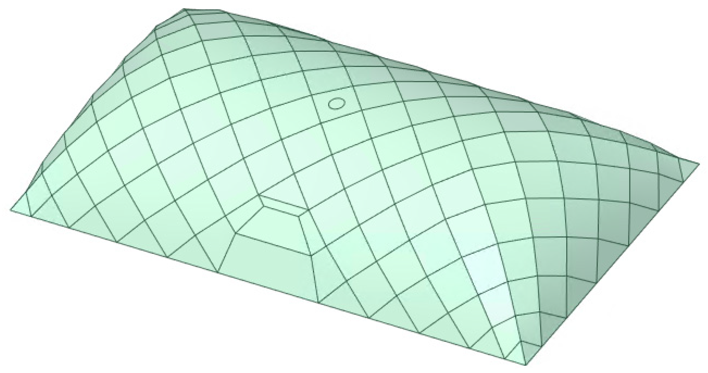
Figure 3.
Power of the fire.

Figure 4.
Temperature of the structure in the very-fast-grow fire event.
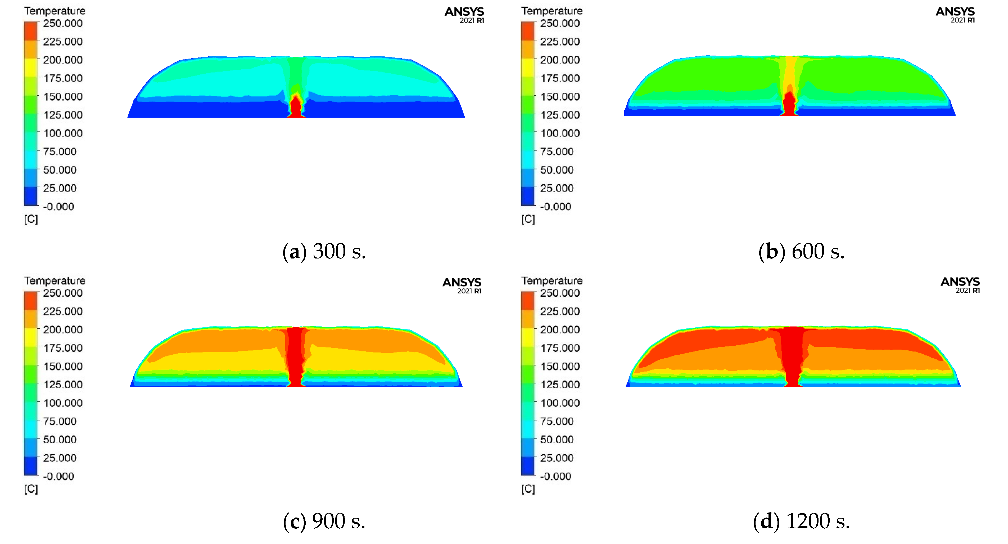
Figure 5.
Temperature of the structure in the fast-grow fire event.

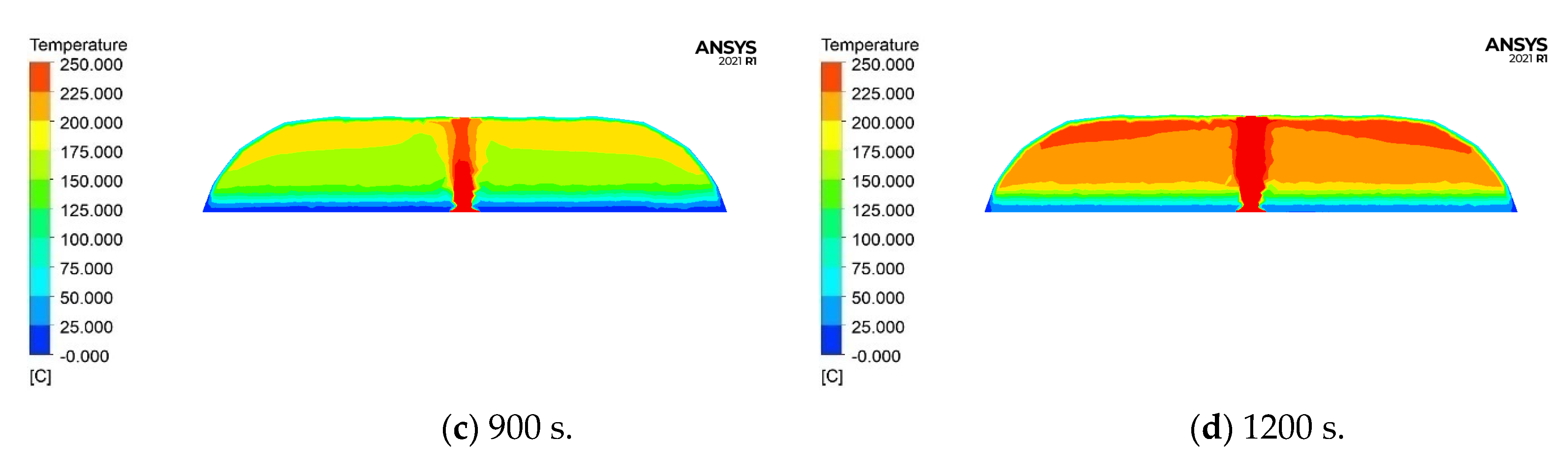
Figure 6.
Temperature of the structure in the normal-grow fire event.
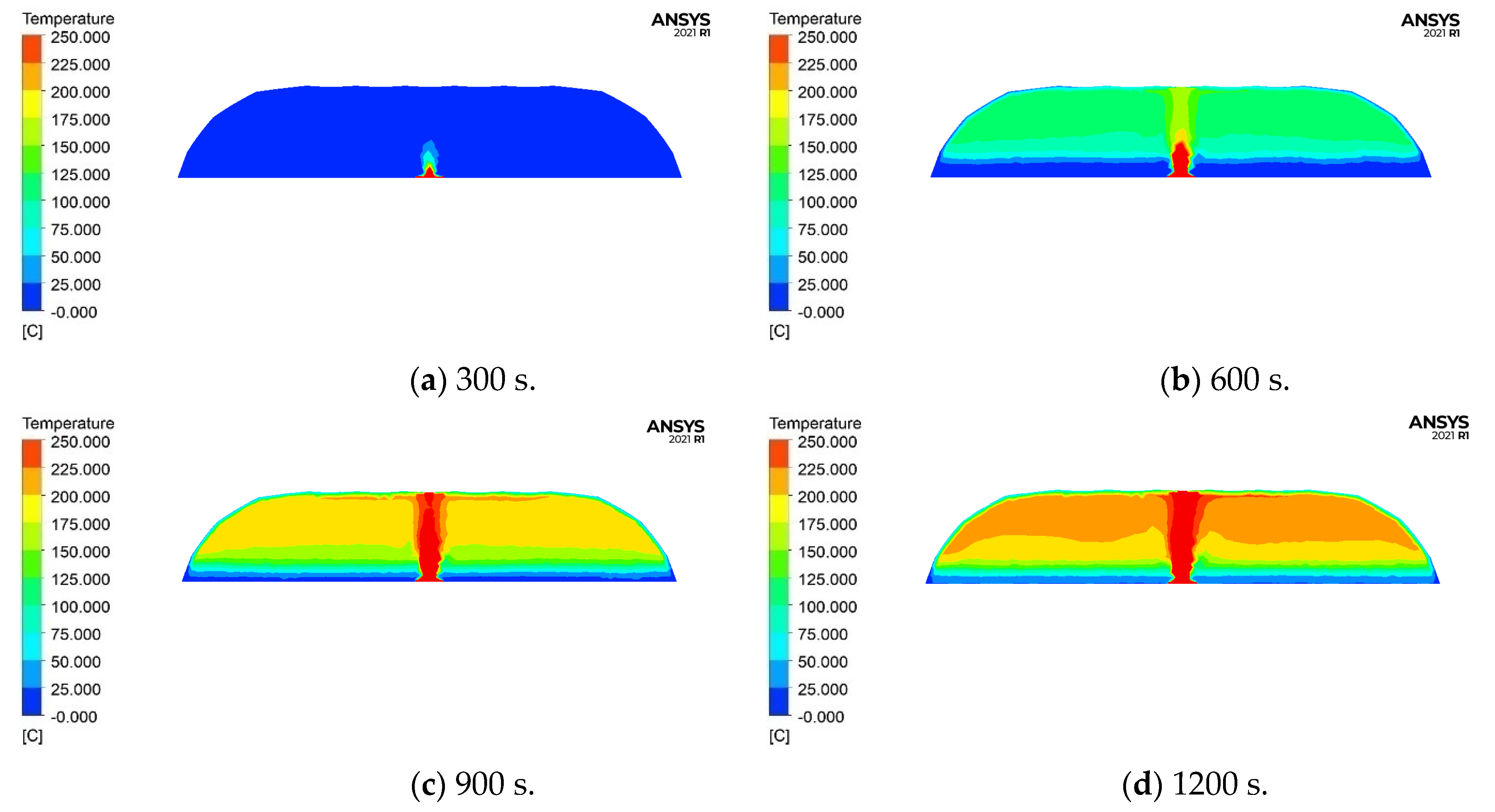
Figure 7.
Temperature of the structure in the slow-grow fire event.
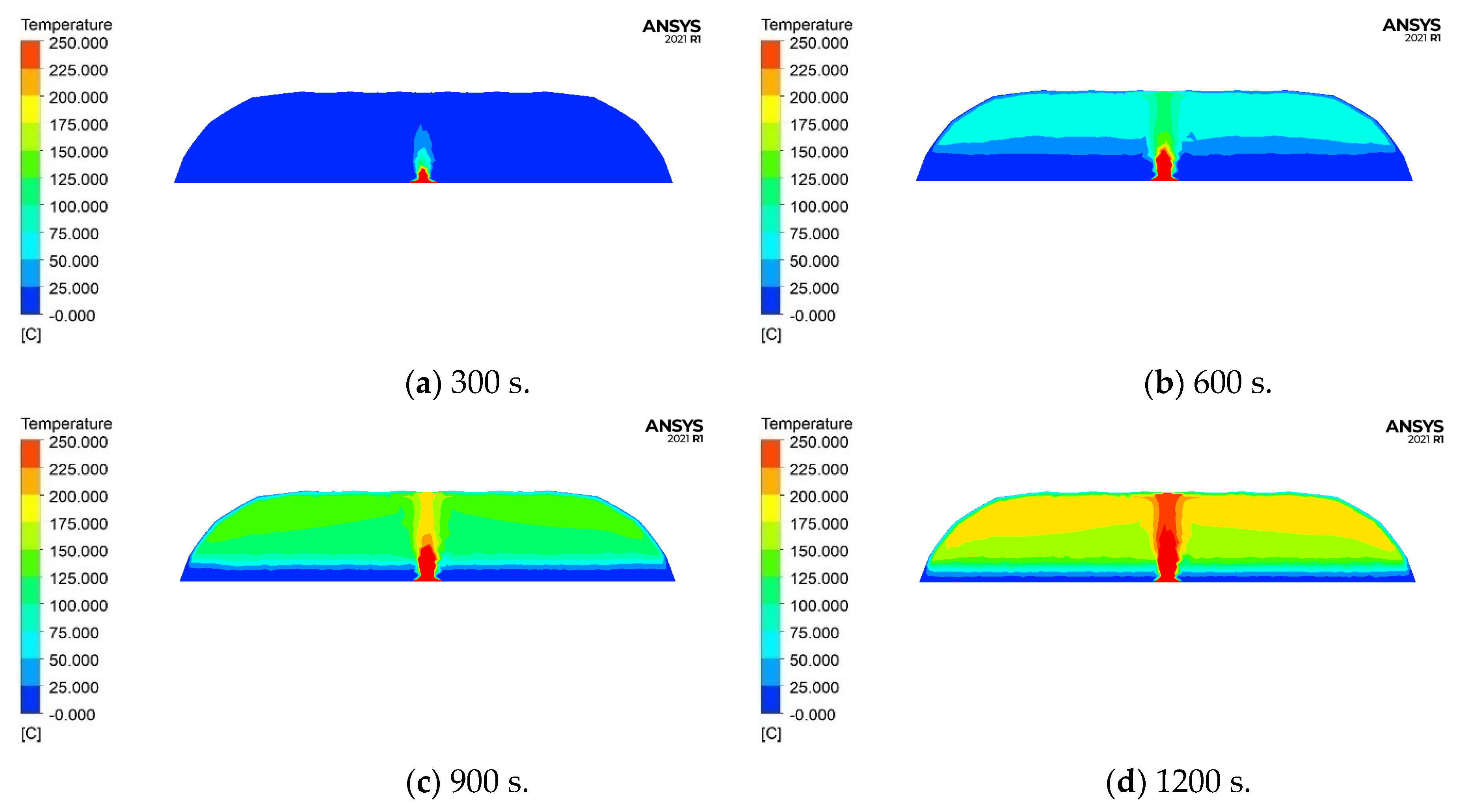
Figure 8.
Temperature of the membrane above the fire.
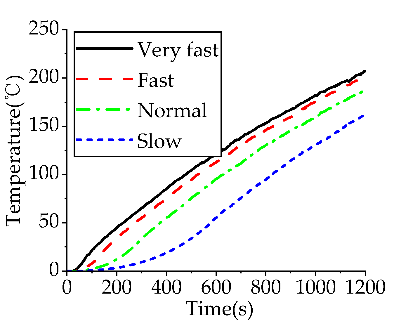
Figure 9.
The FE models.
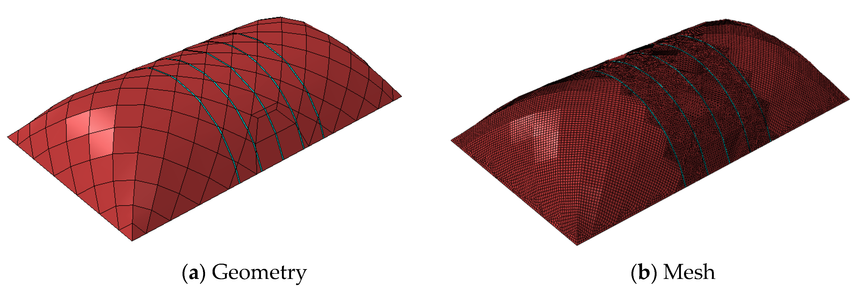
Figure 10.
Stress of the model under pressure difference and gravity (MPa).
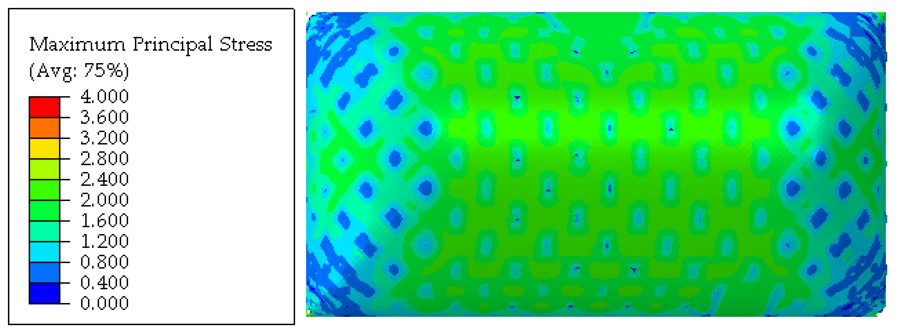
Figure 11.
Temperature on the membrane structures.

Figure 12.
Stress of the membrane in fire conduction (MPa).

Figure 13.
Safety factor of the membrane before and after fire.

Figure 14.
Temperature of the weld joint above the fire.
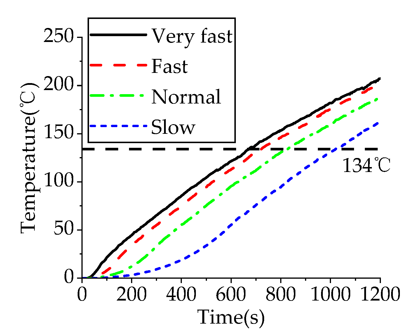
Figure 15.
Time of membrane failure stage in different fire events.
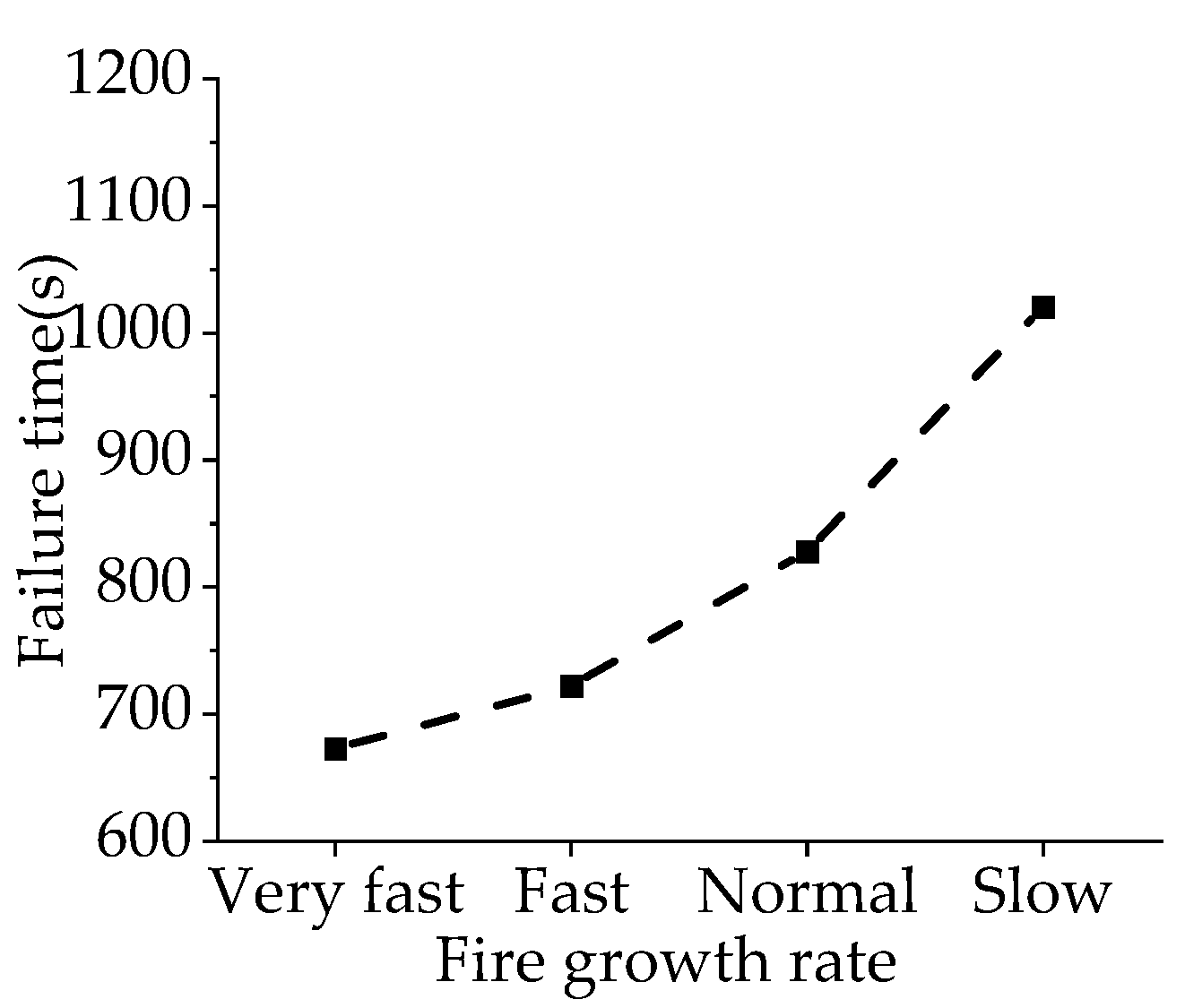
Figure 16.
Pressure difference of the air-supported structure in fire event.

Figure 17.
Pressure difference after the membrane failure.

Figure 18.
Destruction time of air-supported structures in different fire cases.
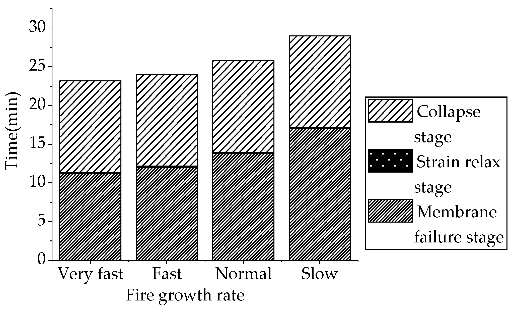
Figure 19.
Stress of center weld joint at different spans and rise-span ratios.

Figure 20.
Stress and allowable temperature of center weld joint at different spans.
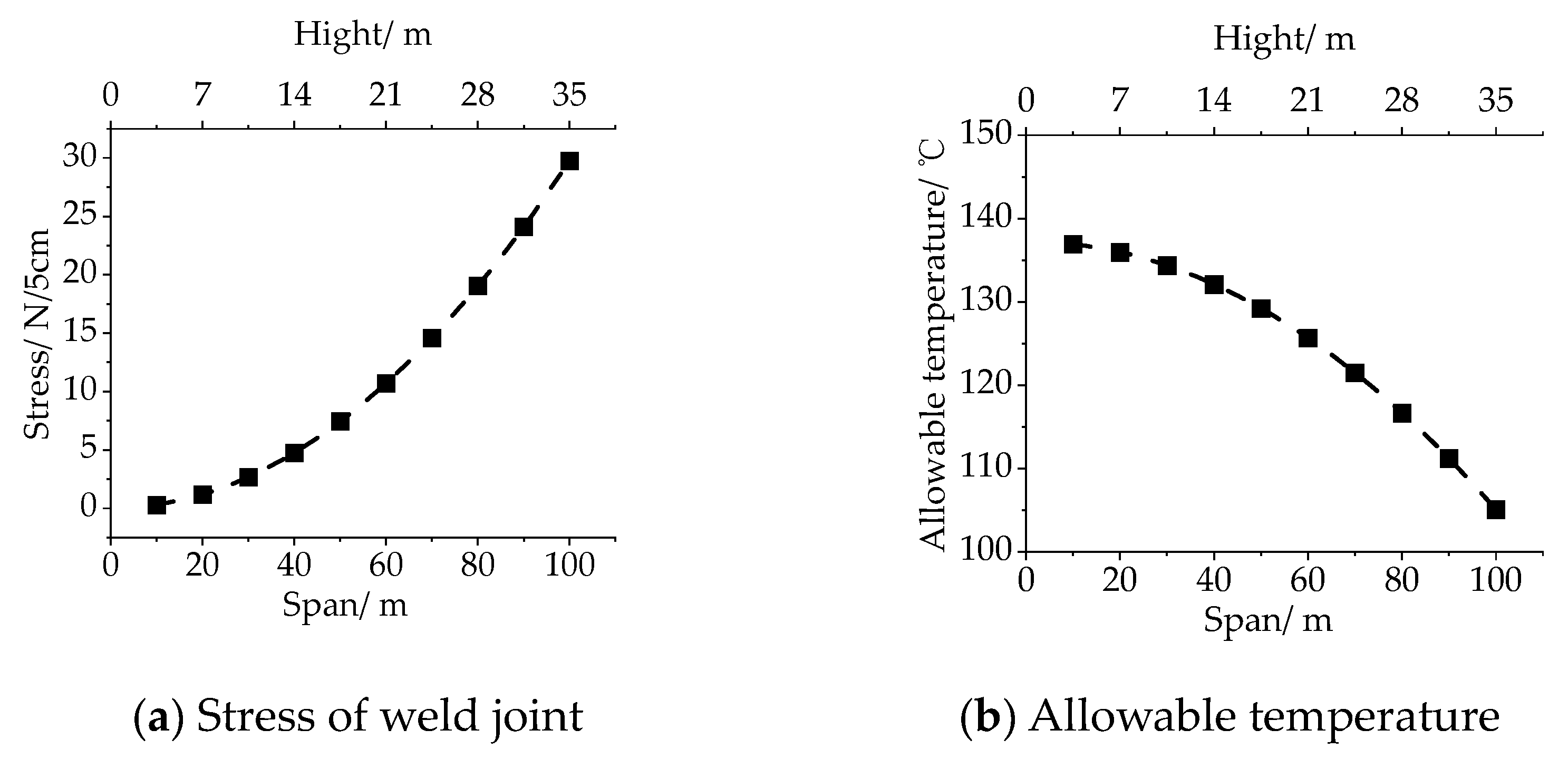
Figure 21.
Center weld-joint temperature of different models.

Figure 22.
Fracture time of different models.
Figure 23.
Collapse of different structures.

Figure 24.
Destruction and evacuation times of different structures.

Table 1.
Parameters of different fires.
| Fire Development Rate | α | t0 |
|---|---|---|
| Very fast | 0.1876 | 73 |
| Fast | 0.0469 | 146 |
| Normal | 0.0117 | 292 |
| Slow | 0.0029 | 584 |
Table 2.
Parameters of membrane.
| Temperature (°C) | Young’s Modulus | Shear Modulus (kN/m) | |
|---|---|---|---|
| Warp (kN/m) | Weft (kN/m) | ||
| 23 | 846.00 | 768.11 | 42.30 |
| 70 | 801.16 | 757.10 | 40.06 |
| 90 | 750.46 | 706.79 | 37.52 |
| 110 | 676.58 | 662.80 | 33.83 |
| 130 | 468.60 | 463.96 | 23.43 |
Table 3.
Leakage area and volume of different air-supported structures.
| Span (m) | Number of Emergency Door | Area of Emergency Door (m2) | Volume (m3) |
|---|---|---|---|
| 20 | 1 | 2.76 | 3358 |
| 40 | 4 | 11.04 | 26,864 |
| 60 | 8 | 22.08 | 90,666 |
| 80 | 16 | 44.16 | 214,912 |
Publisher’s Note: MDPI stays neutral with regard to jurisdictional claims in published maps and institutional affiliations. |
© 2022 by the authors. Licensee MDPI, Basel, Switzerland. This article is an open access article distributed under the terms and conditions of the Creative Commons Attribution (CC BY) license (https://creativecommons.org/licenses/by/4.0/).
Share and Cite
MDPI and ACS Style
Yan, F.; Sun, G.; Xue, S. Study on Membrane Damage and Collapse of Air-Supported Structures under Fire Conditions. Fire 2022, 5, 162. https://doi.org/10.3390/fire5050162
AMA Style
Yan F, Sun G, Xue S. Study on Membrane Damage and Collapse of Air-Supported Structures under Fire Conditions. Fire. 2022; 5(5):162. https://doi.org/10.3390/fire5050162
Chicago/Turabian StyleYan, Fei, Guojun Sun, and Suduo Xue. 2022. "Study on Membrane Damage and Collapse of Air-Supported Structures under Fire Conditions" Fire 5, no. 5: 162. https://doi.org/10.3390/fire5050162